Hunter Fan 99093 Owner's manual
- Category
- Household fans
- Type
- Owner's manual
This manual is also suitable for
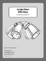
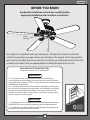
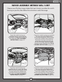
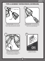
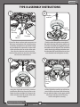
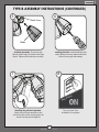
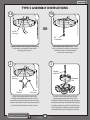
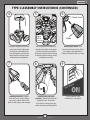
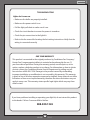
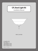
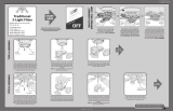
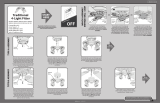
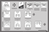
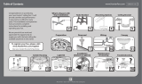
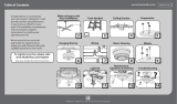
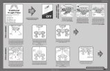
Hunter Fan 99093 is a 4-Light Fitter compatible with a range of Casablanca ceiling fans, including the 51000-58999 and 59500-59999 series. This light kit can be installed using three different assembly methods, depending on the type of switch housing on your fan. Once installed, the Hunter Fan 99093 provides illumination and adds a decorative touch to your ceiling fan. It comes with a one-year warranty against defects in material and workmanship.
Hunter Fan 99093 is a 4-Light Fitter compatible with a range of Casablanca ceiling fans, including the 51000-58999 and 59500-59999 series. This light kit can be installed using three different assembly methods, depending on the type of switch housing on your fan. Once installed, the Hunter Fan 99093 provides illumination and adds a decorative touch to your ceiling fan. It comes with a one-year warranty against defects in material and workmanship.


-
 1
1
-
 2
2
-
 3
3
-
 4
4
-
 5
5
-
 6
6
-
 7
7
-
 8
8
-
 9
9
-
 10
10


Hunter Fan 99093 Owner's manual
- Category
- Household fans
- Type
- Owner's manual
- This manual is also suitable for
Hunter Fan 99093 is a 4-Light Fitter compatible with a range of Casablanca ceiling fans, including the 51000-58999 and 59500-59999 series. This light kit can be installed using three different assembly methods, depending on the type of switch housing on your fan. Once installed, the Hunter Fan 99093 provides illumination and adds a decorative touch to your ceiling fan. It comes with a one-year warranty against defects in material and workmanship.
Ask a question and I''ll find the answer in the document
Finding information in a document is now easier with AI
Related papers
-
Casablanca 99259 Owner's manual
-
 Hunter Fan 99158 Owner's manual
-
 Hunter Fan 99137 User manual
-
 Hunter Fan 54084 Owner's manual
-
 Hunter Fan 99145 User manual
-
 Hunter Fan 99034 Owner's manual
-
Hunter Fan 99153 Owner's manual
-
 Hunter Fan 59015 Owner's manual
-
 Hunter Fan 51049 User manual
-
Hunter Fan Reinert Low Profile User manual


Other documents
-
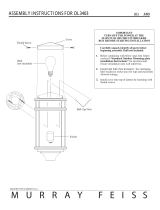 Generation Lighting OL3403CB Installation guide
-
Hunter 99172 Operating instructions
-
-
-
Casablanca 99050 Installation guide
-
 Hunter Fan Company 99146 User manual
-
-
-
 Casablanca Fan Company 99183 User manual
-
Hunter 51023 User manual


