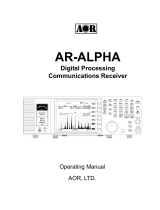
AOR AR-DV1 Owner's manual

Type
Owner's manual

The AOR AR-DV1 is a versatile digital voice receiver that offers a wide range of capabilities for monitoring and recording radio communications. With its ability to decode various digital modes, including D-STAR, DMR, and NXDN, you can listen to a variety of digital transmissions. The AR-DV1 also features an SD card slot, allowing you to record and playback audio, as well as store memory channels and other settings. Additionally, the receiver has a built-in speaker and headphone jack, making it easy to listen to audio directly from the device.

The AOR AR-DV1 is a versatile digital voice receiver that offers a wide range of capabilities for monitoring and recording radio communications. With its ability to decode various digital modes, including D-STAR, DMR, and NXDN, you can listen to a variety of digital transmissions. The AR-DV1 also features an SD card slot, allowing you to record and playback audio, as well as store memory channels and other settings. Additionally, the receiver has a built-in speaker and headphone jack, making it easy to listen to audio directly from the device.

AR-DV1
SDR Digital Voice Receiver
COMMAND LIST
AOR, LTD.
1
Table of Contents
1 PC CONTROL ........................................................................................................................................ 2
1-1 USB INTERFACE ................................................................................................................................ 2
1-2 USB DRIVER ...................................................................................................................................... 2
2 REMOTE CONTROL STATUS ............................................................................................................... 3
3 COMMAND FORMAT ............................................................................................................................. 3
4 RESPONSE FORMAT ............................................................................................................................ 3
5 COMMAND LIST .................................................................................................................................... 5
5-1 SUMMARY IN ALPHABETICAL ORDER . 5
5-2 BASIC CONTROL ... 6
5-3 SQUELCH CONTROL ...... 10
5-4 DIGITAL DECODING .... 13
5-5 RECEIVER OPTIONS ... 14
5-6 CLOCK, ALARM, RECORDING TIMER . 20
5-7 RECEIVER CONFIGURATION ... 22
5-8 SD CARD MANAGEMENT ... 30
5-9 VFO ...... 34
5-10 SEARCH ... 36
5-11 MEMORY CHANNEL ...... 40
5-12 FREQUENCY SCOPE .... 43
2
1 PC CONTROL
1-1 USB INTERFACE
The USB (micro B) connector is designed to connect directly to the USB port of a PC. Make sure that the
USB cable that you are using is not a “charging only” cable, as this type does not allow data transfer. All
functions of the AR-DV1 can be PC controlled with Hyperterminal software, by using our COMMAND LIST.
A USB driver needs first to be installed on the PC.
1-2 USB DRIVER
Once the receiver is connected to the PC, Windows should automatically download and install the
necessary USB driver from Internet (providing of course that the PC is connected to Internet).
Note: If Windows is not detecting the connection, the USB cable you are using is probably only a “charging”
cable, which does not allow data transfer. Please use the proper kind of cable.
Should the operating system fail to automatically install the driver, you may download it manually from:
http://www.silabs.com/products/mcu/Pages/USBtoUARTBridgeVCPDrivers.aspx
Download and install the driver version corresponding to your operating system, as described on that
page.
Following are the specifications for the communication protocol:
Communication speed (selectable by SB command): 115,200 bps (default), 57,600 bps,
38,400 bps, 19,200 bps, 9,600 bps
Data: 8 bit
Stop bit: 1
Parity: None
Flow control: None
Echo: Off
Return Code: (PC->AR-DV1): <CR>(0x0d) <LF> ignore
Return Code: (AR-DV1->PC): <CR><LF>(0x0d, 0x0a)
3
2 REMOTE CONTROL STATUS
Connect the AR-DV1 to a PC and turn power on to the AR-DV1.
When any data is sent from a PC to the AR-DV1, then AR-DV1 will respond to the command and go into
remote control mode. While in the remote control mode, front panel keys, knobs, and main dial will be
disabled, except for the [MHz] key.
To exit from the control command mode, press the [MHz] or send the EX command.
The KEYLOCK function will also be disabled while in the remote control mode.
While Timer Recording is activated, TX, TR, and ZP commands are rejected.
When the AR-DV1 is switched off, only the ZP command (power on command) is accepted.
3 COMMAND FORMAT
<command><CR>
<command><parameter><CR>
<command><parameter 1><SP><parameter 2><SP><parameter 3><CR>
Each command is completed with a <CR>(0x0d).
There is no space between <command> and <parameter>.
Note: SP -- Space
Each command consists of two upper case letters (header) along with operations as required.
All commands use ASCII code which MUST BE IN UPPER CASE (except for the up arrow and down
arrow keys.)
4 RESPONSE FORMAT
Although there is no local echo, a specified response should come back from the AR-DV1 after
confirming the correct command. If an invalid command is sent to AR-DV1, [ ? <CR><LF> (0x3f, 0x0d,
0x0a) ] will be returned as an unrecognized command.
4
NORMAL RESPONSE
<SP><CR><LF> (0x20, 0x0d, 0x0a) to a valid command (without parameter).
<value><SP><CR><LF> to a valid command (with one parameter.)
<value 1><SP><value 2><SP><CR><LF> to a valid command (with two parameters)
RESPONSE BY RESULT CODES
Two digits number will be added to the head of the response.
Example 1: Acquire noise squelch level (NQ command)
Command NQ -> Response 20NQ35<SP><CR><LF> (Normal response: NQ35<SP><CR>LF>)
Example 2: Set Audio gain (AG command) to 10
Command AG10 -> Response 20<SP><CR><LF> (Normal response: <SP><CR><LF>)
RESULT CODES
The result codes are used to display the response to the command by a 2 digit number. By using the result
codes, it’s easier to identify the response as valid, invalid, or continuous status.
First digit: Valid or invalid
1 --- Valid command from AR-DV1 (Automatically sent from the AR-DV1)
2 --- Valid response from PC (Acknowledgment to PC command)
3 --- Invalid command (Not executable)
4 --- Invalid command (Command error, invalid parameter)
5 --- Invalid command (Invalid parameter – out of range)
6 --- Invalid command (Unknown command)
Second digit: Response status
0 --- Last column or single column
1 --- Continuous column
5
5 COMMAND LIST
5-1 Summary in alphabetical order
Command
R/W
Function
Page
Command
R/W
Function
Page
AC
R/W AGC 14
PR
R List pass frequencies 39
AG
R/W Audio gain 6
PR
R Set pass frequencies 39
AS
R/W Auto store 38
PT
R/W Write protect 24
BK
R/W Bank link 38
PW
W Set pass frequencies 39
BP
R/W Beep 22
QP
W Power off, disconnect 6
CI
R/W Tone squelch on/off 11
RE
R/W Result code 26
CN
R/W Tone squelch frequency 12
RF
R/W Receive frequency 7
DC
R/W DCR encryption code 13
RG
R/W Manual gain 14
DI
R/W DCS on/off 12
RN
R/W Serial number 28
DJ
R/W Digital data output 13
RS
W Reset AR-DV1 29
DK
R Acquire digital data 13
RT
R/W Receiver status output 26
DL
R/W Delay time 19
RX
R Receiver status 27
DS
R/W DCS code 12
SB
R/W Communication speed 28
DT
R/W System clock 20
SC
R/W Voice descrambler freq. 18
EX
W End remote control 10
SD DIR
R File directory 30
FD
R Acquire scope data (H) 43
SD INF
R Card information 31
FR
R/W Free time 19
SD MMR
W File restore 34
GL
R Acquire scope data (N) 43
SD MMW
W File backup 33
IF
R/W IF bandwidth 15
SD PLY
W Playback 32
KL
R/W Key backlight color 23
SD PST
R Record/playback status 31
LB
R/W LCD backlight 22
SD REC
W Recording 32
LC
R/W Frequency data output 24
SD RSQ
R/W Squelch skip 33
LD
R/W LCD dimmer 22
SE
W Search bank setting 36
LM
R S-meter reading 25
SG
R/W Search group 38
LN
R/W LCD contrast 23
SH
R/W Frequency step adjust 8
LQ
R/W Level squelch 11
SI
R/W Voice descrambl. on/off 18
LS
R/W Auto notch 15
SL
R/W Search bank low limit 37
LT
R/W S-meter data output 25
SP
R/W Sleep timer 20
MA
R Read memory channel 41
SQ
R/W Select squelch 10
MB
W Delete memory bank 43
SR
R Read search bank 36
MD
R Decoding mode 8
SS
W Exec. program search 37
MG
R/W Scan group 42
ST
R/W Frequency step 7
MM
W Last ch. memory regis. 29
SU
R/W Search bank upper limit 37
MP
R/W Pass channel 42
SX
W Delete search bank 37
MQ
W Delete memory channel 43
TI
R/W Priority receive interval 18
MR
W Read memory 41
TR
R/W Recording timer 21
MS
W Memory scan 41
VE
R/W VFO search setting 35
MW
R/W Set memory bank 42
VF
W VFO 34
MX
W Set memory channel 42
VI
R VFO Information 35
NQ
R/W Noise squelch 10
VQ
R/W Voice squelch 11
NR
R/W Noise reduction 15
VR
R Firmware version 28
OF
R/W Offset receive 16
VS
W VFO search 34
OL
R/W Offset frequency 16
WI
R AR-DV1 model 28
OX
R/W Monitor offset 17
ZI
R/W Receiver ID 24
PD
W Delete pass frequencies
40
ZK
W Move to next F/B/CH 10
PO
R/W Priority receive on/off 17
ZJ
W Move to prev. F/B/CH 9
PP
R/W Priority receive channel 17
ZP
W Power on, connect 6
6
COMMAND DETAILS
5-2 BASIC CONTROL
POWER ON, CONNECT
ZP
Power on
ZPnn / ZP
(nn = 00 ~ 99 : ID) Default: 00
Response: AOR AR-DV1 VER. XXXX READY
Result code: 10 --- AR-DV1 VER. XXXX READY
20 --- Turned on successfully (AR-DV1)
40 --- Command format error
50 --- Parameter out of range
Note: The Power supply must be connected.
POWER OFF, DISCONNECT
QP
Power off
QPnn /QP
(nn = 00 ~ 99 : ID) Default: 00
Response: AOR AR-DV1 GOTO SHUTDOWN
Result code: 10 --- Power off completed
20 --- Power off processing
(AR-DV1 GOTO SHUTDOWN)
40 --- Command format error
50 --- Parameter out of range
Note: The Power supply must be connected.
AUDIO GAIN
AG
AG
nn
(nn: 00 ~ 99) Default: 00
To read:
AG<CR>
Response:
AGnn
Result code: 20 --- Read successfully
40 --- Command format error
50 --- Parameter out of range
7
RECEIVE FREQUENCY
RF
RFnnnn.nnnnn
(nn: in MHz, Range: 0.1 ~ 1300.0)
To read:
RF<CR>
Response:
RFnnnn.nnnnn (in MHz)
Result code: 20 --- Set successfully
30 --- Entered an invalid frequency for the current receive mode
40 --- Command format error
50 --- Parameter out of range
Note: In VFO mode, setting frequency becomes the receive frequency.
In VFO search, if the set frequency is within a range of VFO-A and VFO-B, it will become the
receive frequency and continues searching. If the set frequency is out of range of VFO-A
and VFO-B, a result code (30) will be returned from the AR-DV1.
In program search, if the set frequency is within a range of the search bank, it will become the
receive frequency and continues searching. If the set frequency is out of range of the search
bank, a result code (30) will be returned from the AR-DV1.
FREQUENCY STEP
ST
STnnn.nn
nnn.nn (in kHz) : 0.01, 0.05, 01, 05, 1.0, 2.0, 5.0, 6.25, 7.50, 8.33, 9.0, 10.0,
12.5, 15.0, 20.0, 25.0, 30.0, 50.0, 100.0, 500.0 (default: 010.00)
To read:
ST<CR>
Response:
STnnn.nn
Result code: 20 --- Read successfully
30 --- Invalid setting
40 --- Command format error
50 --- Parameter out of range
Note: In VFO mode or VFO search mode, the frequency step will be changed immediately.
In program search mode, executing this command will work until another bank is selected
by using the SS command or another receive mode is selected.
In memory read mode, it will remain until another channel is selected or another receive mode
is selected. This command will not work in the memory read and scan modes.
8
FREQUENCY STEP ADJUST
SH
SHnnn.nn
: nnn.nn: (in kHz) :0.05, 0.25, 0.5, 1, 2.5, 3.12, 3.75, 4.16, 4.5, 5.0, 6.25, 10.0,
12.5, 15.0, 25.0, 50.0, 250.0 (default: 000.00)
To read:
SH<CR>
Response:
SHnnn.nn
Result code: 20 --- Read successfully
30 --- Invalid setting
40 --- Command format error
50 --- Parameter out of range
Not
e: In VFO mode or VFO search mode, the frequency step will be changed immediately.
In program search mode, executing this command will work until another bank is selected
by using the SS command or another receive mode is selected.
In memory read mode, this command will be effective until another channel is selected
or another receive mode is selected.
This command will not work in the memory scan mode.
DECODING MODE
MD
M
d
dan / MDda
(default: MD001)
To read:
MD<CR>
Response:
MDdan
Parameters: d: Digital decode mode
0: Digital signal not decoded
1: D-STAR
2: YAESU
3: ALINCO
4: D-CR/NXDN
5: P-25 (APCO25)
6: dPMR
7: DMR
a: Digital mode setting
0: Digital auto decode mode
9
1: D-STAR
2: YAESU
3: ALINCO
4: D-CR/NXDN
5: P-25 (APCO25)
6: dPMR
7: DMR
F: Digital decode OFF
n: Analog receive mode
0:FM
1:AM
2:SAH
3: SAL
4:USB
5:LSB
6: CW
Note: “n” parameter may be omitted and the analog receive mode is set to NFM.
When “n” is set other than 0, the digital decode mode is set to OFF and “a”
parameter is automatically forced to “F”.
Result code: 20 --- Read successfully
40 --- Command format error
50 --- Parameter out of range
Note: In VFO mode or VFO search mode, the frequency step will be changed immediately.
In program search mode, executing this command will work until another bank is selected by using
the SS command or another receive mode is selected. In memory read mode, this command will
be effective until another channel is selected or another receive mode is selected.
This command will not work in the memory scan mode.
MOVE TO PREVIOUS FREQUENCY, BANK, CHANNEL
ZJ
ZJ
(immediate command)
Result code:
20 --- Read successfully
40 --- Command format error
10
MOVE TO NEXT FREQUENCY, BANK, CHANNEL
ZK
ZK
(immediate command)
Result code:
20 --- Read successfully
40 --- Command format error
END REMOTE CONTROL
EX
EXnn, EX
(nn: Receiver’s ID. If omitted, nn=00)
Result code:
20 --- Disconnected successfully
40 --- Command format error
50 --- Parameter out of range
5-3 SQUELCH CONTROL
SELECT SQUELCH
SQ
SQn
(n: 0 ~ 2 default: 0)
0: Auto
1: Noise squelch
2: Level squelch
Result code:
20 --- Read successfully
40 --- Command format error
50 --- Parameter out of range
NOISE SQUELCH
NQ
NQnn
(nn: 00 ~ 99 default: 00)
00: Squelch fully opened
99: Squelch fully closed
Result code:
20 --- Read successfully
40 --- Command format error
50 --- Parameter out of range
11
LEVEL SQUELCH
LQ
LQnn
(nn: 00 ~ 99 default: 00)
00: Squelch fully opened
99: Squelch fully closed
Result code:
20 --- Read successfully
40 --- Command format error
50 --- Parameter out of range
VOICE SQUELCH
VQ
VQn VTppp VLr
n: 0, 1 0: Function Off (default)
1: Function On
ppp: 000 ~ 255 (default: 020)
Delay time in 0.1 second incremental
r: 0 ~ 7 Squelch level (default: 4)
Result code:
20 --- Read successfully
40 --- Command format error
50 --- Parameter out of range
Note: Function ON/OFF can be set independently in each VFO, bank, or channel.
Delay time and squelch level are applied for the entire operation.
TONE SQUELCH ON/OFF
CI
CIn
(n: 0, 1 default: 0)
0: Tone squelch OFF
1: Tone squelch ON
Result code:
20 --- Read successfully
40 --- Command format error
50 --- Parameter out of range
Note: This command may be used for each VFO, bank, and channel.
12
TONE SQUELCH FREQUENCY
CN
CNnn
(nn: 00 (response only), 01 ~52, 99 (search))
default:99
When tone search is activated, response will be CN99nn.
If tone is detected, nn = 01 ~ 52
If no tone is detected, nn = 00
Result code:
20 --- Read successfully
40 --- Command format error
50 --- Parameter out of range
Note: This command may be used for each VFO, bank, and channel.
DCS ON/OFF
DI
DI
n
(n: 0, 1 default: 0)
0: DCS OFF
1: DCS ON
Result code:
20 --- Read successfully
40 --- Command format error
50 --- Parameter out of range
Note: This command may be used for each VFO, bank, and channel.
DCS CODE
DS
DSnnn
(nnn: 000 (response only), 017 ~754, 999)
999 is code search. Default:999
When code search is activated, response will be DS999nnn.
If code is detected, nnn = 017 ~ 754
No code is detected, nnn = 000
Result code:
20 --- Read successfully
40 --- Command format error
50 --- Parameter out of range
Note: This command may be used for each VFO, bank, and channel.
13
5-4 DIGITAL DECODING
DIGITAL CR, SIMPLE ENCRYPTION CODE DECODING
DC
DCnnnnn
(nnnnn: 00000 ~32767)
default:00000
Result code:
20 --- Read successfully
40 --- Command format error
50 --- Parameter out of range
Note: Used for non-licensed low power communication system, in Japan only.
DIGITAL DATA OUTPUT
DJ
DJn
(n: 0, 1)
n:0 Data output OFF (default)
n:1 Data output ON
When activated, the digital data will be displayed on the LCD or output from remote
connector.
Result code:
20 --- Read successfully
40 --- Command format error
50 --- Parameter out of range
ACQUIRE DIGITAL DATA
DK
DKyyy
Acquire the latest message.
Result code:
20 --- Read successfully
40 --- Command format error
Note: When DJ command is set to 1, data will always be output, regardless of this command.
14
5-5 RECEIVER OPTIONS
These options are available for each VFO, bank, and channel settings except the OL command (offset
frequency setting). The OL command is applied for entire receiver’s settings.
AGC (AUTOMATIC GAIN CONTROL)
AC
ACn
(n: 0 ~ 3) (default: 0)
n=0 AGC Fast
n=1 AGC Medium
n=2 AGC Slow
n=3 MANUAL GAIN
To read:
AC<CR>
Response:
ACn
Result code: 20 --- Read successfully
30 --- Detector mode is selected other than Analog AM modes (AM, SSB, CW)
40 --- Command format error
50 --- Parameter out of range
Note: This command works only in Analog AM modes (AM, SSB, CW). An error code will be sent in all
other modes.
MANUAL GAIN
RG
RGnnn
(nnn: 000 ~ 110)
nnn=000 Gain minimum
nnn=110 Gain maximum (default:099)
To read:
RG<CR>
Response:
RGnnn
Result code: 20 --- Read successfully
40 --- Command format error
50 --- Parameter out of range
Note: The manual gain setting is valid only when AGC is selected MANUAL GAIN (AC3).
However, the parameter setting or readout is available regardless of AGC setting.
15
IF BANDWIDTH
IF
IF
n
FM: n = 0->200KHz, 1->100KHz, 2->30KHz, 3->15KHz, 4->6KHz (default: 3 FM)
AM: n = 0->15KHz, 1->8KHz, 2->5.5KHz, 3->3.8KHz
SAH, SAL n=0->5.5KHz, 1->3.8KHz
USB LSB n=0->2.6KHz, 1->1.8KHz
CW n=0->500Hz, 1->200Hz
To read:
IF<CR>
Response:
IFn, IFnn
Result code: 20 --- Read successfully
30 --- Invalid decode mode
40 --- Command format error
50 --- Parameter out of range
AUTO NOTCH
LS
LSn
n: 0 ~ 3
n: 0 OFF (default)
n: 1 Depth Low
n: 2 Depth Medium
n: 3 Depth High
To read:
LS<CR>
Resp
onse:
LSn
Result code: 20 --- Read successfully
40 --- Command format error
50 --- Parameter out of range
NOISE REDUCTION
NR
NRn
n: 0 ~ 3
n: 0 OFF (default)
n: 1 Reduction Low
n: 2 Reduction Medium
16
n:3 Reduction High
To read:
NR<CR>
Response:
NRn
Result code: 20 --- Read successfully
40 --- Command format error
50 --- Parameter out of range
OFFSET RECEIVE
OF
OFsnn
nn: 00 ~ 39 (default: 00)
s: +/- Offset direction
Note: The “s” parameter may be omitted when nn = 00.
To read:
OF<CR>
Response:
OFnns
Result code: 20 --- Read successfully
40 --- Command format error
50 --- Parameter out of range
OFFSET FREQUENCY
OL
OLnn RFffff.fffff
nn: 00 ~ 39 Offset number
(default: Offset number 01 ~ 19 is the same as number 20)
ffff.fffff : Offset frequency (in MHz)
Note: Offset number 20 ~ 39: Factory preprogrammed (cannot be changed)
01 ~ 19: User programmable
00: Offset frequency is set to 0 Hz.
To read:
OLnn<CR>
Response:
OLnn RFffff.fffff
Result code: 20 --- Read successfully
30 --- Invalid offset frequency
40 --- Command format error
50 --- Parameter out of range
17
MONITOR OFFSET
OX
OXn
n: 0, 1 (default: 0)
n:0 Monitor, Offset OFF
n:1 Monitor, Offset ON
Note: When an offset receive is available, offset frequency will be received.
When an offset receive is not possible, squelch will open and receive the
current frequency.
To read:
OX<CR>
Response:
OXn
Result code: 20 --- Read successfully
40 --- Command format error
50 --- Parameter out of range
Note: This setting won’t be saved onto the last channel memory. Once the power
switch is turned off, the OX will be set to OX0.
PRIORITY RECEIVE ON/OFF
PO
POn
n: 0, 1 (default: 0)
To read:
PO<CR>
Response:
POn
Result code: 20 --- Read successfully
30 --- Priority channel not registered
40 --- Command format error
50 --- Parameter out of range
PRIORITY RECEIVE CHANNEL
PP
PPbbcc
bb: bank (default: 00)
cc: channel (default: 00)
To read:
PP<CR>
18
Response:
PPbbcc
Result code: 20 --- Read successfully
40 --- Command format error
50 --- Parameter out of range
Note: Priority channel can be set even when the designated channel is not registered.
PRIORITY RECEIVE INTERVAL
TI
TImm
mm: 01 ~ 99 in seconds (default: 05)
To read:
TI<CR>
Response:
TImm
Result code: 20 --- Read successfully
40 --- Command format error
50 --- Parameter out of range
VOICE DESCRAMBLER FREQUENCY (Not available for the US consumer version.)
SC
SCnnn
(nnn: 200 ~ 700) in 10Hz incremental, default: 200.
To read:
SC<CR>
Response:
SCnnn
Result code: 20 --- Read successfully
30 --- Invalid parameter (Parameter should be set as FM within 15kHz bandwidth)
40 --- Command format error
50 --- Parameter out of range
VOICE DESCRAMBLER ON/OFF (Not available for the US consumer version.)
SI
S
i
n
(n: 0, 1) (default: 0)
n:0 OFF
n:1 ON
To read:
SI<CR>
  • Page 1 1
  • Page 2 2
  • Page 3 3
  • Page 4 4
  • Page 5 5
  • Page 6 6
  • Page 7 7
  • Page 8 8
  • Page 9 9
  • Page 10 10
  • Page 11 11
  • Page 12 12
  • Page 13 13
  • Page 14 14
  • Page 15 15
  • Page 16 16
  • Page 17 17
  • Page 18 18
  • Page 19 19
  • Page 20 20
  • Page 21 21
  • Page 22 22
  • Page 23 23
  • Page 24 24
  • Page 25 25
  • Page 26 26
  • Page 27 27
  • Page 28 28
  • Page 29 29
  • Page 30 30
  • Page 31 31
  • Page 32 32
  • Page 33 33
  • Page 34 34
  • Page 35 35
  • Page 36 36
  • Page 37 37
  • Page 38 38
  • Page 39 39
  • Page 40 40
  • Page 41 41
  • Page 42 42
  • Page 43 43
  • Page 44 44
  • Page 45 45
  • Page 46 46

AOR AR-DV1 Owner's manual

Type
Owner's manual

The AOR AR-DV1 is a versatile digital voice receiver that offers a wide range of capabilities for monitoring and recording radio communications. With its ability to decode various digital modes, including D-STAR, DMR, and NXDN, you can listen to a variety of digital transmissions. The AR-DV1 also features an SD card slot, allowing you to record and playback audio, as well as store memory channels and other settings. Additionally, the receiver has a built-in speaker and headphone jack, making it easy to listen to audio directly from the device.

Ask a question and I''ll find the answer in the document

Finding information in a document is now easier with AI