Page is loading ...

1
Contact local building or fire officials about restrictions
and installation inspection requirements in your area.
SAVE THESE INSTRUCTIONS
Aug. 2007
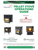
Corn / Pellet Stove
Model: #OLV-PC
Please read this entire manual before installation and use of the
corn/pellet fuel burning room heater.
Failure to follow these instructions could result in property damage,
bodily injury or even death.
OPERATING & MAINTENANCE MANUAL

2
TABLE OF CONTENTS
Features…………………………………………………………………………………………….3
Safety Information………………………………………………………………………………4-5
Installation………………………………………………………...4
Precautions………………………………………………………..4
Safety Devices……………………………………………………..5
Circuit Control Board…………………………………………………………………………….6
Operating Instructions………………………………………………………………………….7-9
Fuel Quality / Storage…………………………………………….7
Pre-lighting Checklist…………………………………………….7
Thermostat Control…………………………………………..…..7
Burning with corn…………………………...……………………8
Burning with wood pellets………………………………………..8
Burning with corn / pellet mix…………………………………...9
Heat Setting / Damper Setting Chart……………………………9
Subsequent Burn Procedures…………………………………...10
Shutting OFF the Stove…………………………………………10
Maintenance Instructions…………………………………………………………………….11-14
Daily Maintenance……………………………………………….11
Weekly Maintenance…………………………………………11-12
2-Month Maintenance………………………………………..12-14
Annual Maintenance…………………………………………….14
Troubleshooting…………………………………………………………………………………..15
Control Board Diagnostics Troubleshooting…………………………………………………...16
Replacement Parts…………………..………………………………………………………..17-18
Description……………………………………………………….17
Illustration………………………………………………………..18
Diagnostic Features……………………………………………...10
Complete warranty information and return to: Kozy Heat Fireplaces
Attention: Warranty Registration
P.O. Box 577
Lakefield, MN. 56150

3
OLIVIA
CORN / PELLET STOVE
FEATURES
Tested for use with corn, pellets or an unlimited mixture.
Convenient Corn / Pellet switch
Circuit Control Board
Hopper Capacity:
Corn: 90 lbs
Pellets: 80 lbs
Hearth Extension
Ash Drawer with easy access
Electronic Ignition - Standard
Thermostatic Control - Optional (recommended)
Ash Dump Handle
Heat Exchange
Tube Cleaner
Figure shown with optional decorative grill.

4
INSTALLATION: This stove must be installed by a qualified installer in accordance with the installation manual provided.
Improper installation and /or maintenance may create a fire hazard, resulting in an unsafe condition, poor performance, and
may void your warranty.
1. Please read this entire manual before operating this stove. Make sure the installer of this product reviews the operating
procedures, all maintenance requirements, and answers any questions you may have.
2. This stove is approved for use with shelled corn or wood pellets only. An unlimited mixture of shelled corn / wood pellets
may also be used.
3. Please be aware that it is normal for the stove to give off odors during the initial burn period. This is short-term and the
result of paint curing and other agents used in the manufacturing process.
4. This stove will be HOT WHILE IN OPERATION. Keep children, clothing, and furniture away from all stove surfaces.
Direct contact with stove surfaces while in operation may cause severe burns.
5. This stove has safety interlock switches built into the circuit control board which will not allow continuous burning in the
event of a problem. Keep the door, ash drawer and hopper lid closed whenever this stove is in operation. All exhaust con-
nections must be tightly sealed to prevent the possibility of carbon monoxide from entering the home.
6. The combustion air intake pipe should be connected to an outside fresh air source. This will prevent ‘smoke back’ into the
house in circumstances such as a power outage.
CAUTION: Operate this stove only with the fuel hopper lid closed. Failure to do so may result in emission of combustion
products from the hopper under certain conditions. This stove is equipped with a safety interlock device which will turn
off auger operation when the hopper lid is opened. To prevent the fire in the burn pot from extinguishing, do not allow
hopper lid to remain open longer than 30-45 seconds. If hopper lid is left open, the control board will continue to operate
as normal, but the auger will not cycle until the stove has been shut off and restarted.
DISPOSAL OF ASHES: Ashes should be placed in a metal container with a tight fitting lid. The closed container of ashes
should be placed on a noncombustible floor or on the ground, well away from all combustible materials, pending final dis-
posal. If the ashes are disposed of by burial in soil or otherwise locally dispersed, they should be retained in the container
until all cinders have thoroughly cooled.
NEVER USE GASOLINE, gasoline-type lantern fluid, kerosene, charcoal lighter fluid or similar liquids to start or ‘freshen
up’ a fire in the stove. Keep all such liquids well away from stove while in use.
SOOT AND FLY ASH: Formation and Need for Removal. The products of combustion will contain small particles of flyash.
The flyash will collect in the exhaust venting system and restrict the flow of the flue gases. Incomplete combustion, such as
occurs during startup, shutdown, or incorrect operation of the room heater will lead to some soot formation which will collect
in the exhaust system. The exhaust venting system should be inspected at least once a year to determine if cleaning is neces-
sary.
DO NOT USE ANOTHER MANUFACTURER’S BURN POTS, GRATES, OR ANY OTHER COMPONENT WHICH
HAVE NOT BEEN TESTED OR APPROVED FOR USE WITH THIS STOVE.
DO NOT OVER FIRE THIS STOVE. (OVERFILL BURN POT AT STARTUP). Follow all instructions regarding the proper
use of this stove.
CAUTION: The electrical components of this stove are not owner serviceable. Contact your dealer for proper diagnosis of
any electrical problems that may occur and to provide service.
SAFETY INFORMATION
SAFETY PRECAUTIONS

5
High Limit Switch - The high limit switch is an ‘overheat’ safety switch which shuts off fuel feed if the stove exceeds tempera-
tures above the normal operating temperature. This switch is a manual reset type.
Proof of Fire Switch - (P.O.F). Responds to temperature rise in the exhaust system. The stove will stop operating if tempera-
tures above 110°F are not met during startup or drops below 90° F during normal operation.
Vacuum Switch - When stove is ‘ON’, the exhaust fan creates vacuum inside the firebox. The control board continuously
monitors for vacuum during operation . If vacuum pressure is lost for longer than 30 seconds, the stove will shut down.
Interlock Safety Switch - Located on the top flange of hopper. If hopper lid is opened, the interlock safety switch deactivates
the auger. This switch has been installed for your safety and should never be disconnected for any reason.
View: Back of stove with hopper removed.
Interlock Safety Switch
Thermostat Terminals
Exhaust Fan
Terminal Block
Vacuum Switch
Proof of Fire Switch (P.O.F.)
Room Fan
Intake Air Damper
SAFETY DEVICES
High Limit Switch

6
FUNCTIONS
A. ON/OFF:
Turns the circuit control board ‘ON’ and ‘OFF’. It is also used
to ‘reset’ the board after switching to Diagnostic mode. The
ON/OFF LED light will blink for the first 10 minutes. When
successful start-up is achieved, the light will remain steady.
NOTE: If a thermostat is installed, the ON/OFF LED light will
blink continuously until the thermostat calls for heat, at which
time the light will remain steady. When the set temperature is
reached, the light will resume blinking.
B. AUGER:
Corn Setting:
The auger will run 3 times within the first 30 seconds after the
control circuit board has been turned ‘ON’. The #1 heat level
LED light will turn on. The auger will start operating 8 ½ min-
utes after the control circuit board has been turned ‘ON’. The
AUGER button allows you to manually auger fuel into burn
pot on startup, if needed. When sufficient heat has been applied
to the Proof of Fire switch (P.O.F.), the room fan will turn
‘ON’.
IMPORTANT: If the auger button is pressed and held for 2
minutes or more during normal operation, the control circuit
board will ‘shutdown’. This is an over fire safety precaution.
NOTE: If stove was turned ‘OFF’ and not unplugged, it will
revert back to previous setting at next startup.
Pellet Setting:
The auger will run 3 times within the first 30 seconds after
control circuit board has been turned ‘ON’. The #1 heat level
LED light will turn on and auger will cycle for 4 minutes. Dur-
ing this period the pellets will ignite automatically. After 8 ½
minutes the auger will resume cycling. The AUGER button
allows you to manually auger fuel into burn pot on start up if
needed. When sufficient heat has been applied to the Proof of
Fire switch (P.O.F.), the room fan will turn ‘ON’.
IMPORTANT: If the auger button is pressed and held for 2
minutes or more during normal operation, the control circuit
board will ‘shutdown’. This is an over fire safety precaution.
NOTE: If stove was turned ‘OFF’ and not unplugged, it will
revert back to previous setting.
C. FAN:
Adjusts the room fan on heat setting levels 1& 2 only. The fan
initially starts on HIGH. Press the fan button once to set to
LOW. Pressing the fan button again returns fan to HIGH.
On heat levels #3-#5 the fan runs on HIGH only.
D. HEAT LEVEL:
Advances heat settings between level #1 and level #5. If level
#5 is selected, depressing button again will return heat setting
to level #1. The ‘LED’ light indicates the active heat setting.
E. AUGER TRIM :
Adjusts fuel feed rate in the #1 heat setting only.
Auger trim level 1:
- (#1 LED light is on).
Auger trim level 1 High:
- Press auger trim button once.
(#1 & #4 LED lights are on).
Auger trim level 1 Low:
- Press auger trim button a second
time. (#1 & #3 LED lights are on).
Pressing auger trim button a third time will return setting to
level 1.
ON / OFF LED light
Auger LED light
Heat level settings
Corn setting
Pellet setting
CIRCUIT CONTROL BOARD

7
FOR USE WITH CORN OR WOOD PELLETS ONLY - OR AND UNLIMITED MIX OF BOTH
Contact your dealer for information on where to purchase high quality fuel products.
SHELLED CORN
Corn must be 15% or less moisture content. Corn must be dry, clean, and of good quality. Wet and /or poor quality corn will
result in poor burn performance.
NOTE: Screen corn with excessive grain dust. Remove large pieces of cob and corn stocks.
STORAGE: Shelled corn should be stored where it will not absorb moisture. Do not store corn within the clearance require-
ments or in an area that would hinder routine cleaning & maintenance. Keep corn tightly covered to prevent rodents.
WOOD PELLETS
STORAGE: To prevent moisture absorption, wood pellets should be left in their original sealed bag until using. Pellets with
excessive moisture may plug auger and possibly cause damage.
Hopper filled with fuel: corn, pellets, or a mixture of both.
Hopper lid closed.
Ash dump, located in bottom of burn pot, in ‘closed’ position.
Burn pot properly seated.
Control circuit board pivoted clockwise to ‘exposed’ position.
Intake air damper set to 1/4 open position.
If thermostat (recommended) is installed, circuit control board set to ‘MANUAL’ for first 10
minutes before switching to ‘THERMOSTAT setting.
If thermostat is not installed, set the circuit control board to ‘MANUAL’ at all times.
OPERATING INSTRUCTIONS & MAINTENANCE GUIDELINES
INITITIAL PRELIGHTING CHECKLIST
WALL / REMOTE THERMOSTAT CONTROL (recommended)
This stove is capable of operating on a wall thermostat or a thermostat with remote. A feature has been built into the
circuit control board which delays time between each heat setting to allow the stove to react at each subsequent level.
It will take the stove approximately 2-5 minutes for the control board to operate at the full capacity for the heat level it
has been set to. As the room temperature falls below the thermostat temperature setting, the stove will operate at one
of the (5) settings previously chosen. When the room temperature reaches the thermostat set temperature, the stove
will automatically operate at the lowest setting (#1). NOTE: The LED will remain lit at chosen setting. Installing a
thermostat will reduce fuel consumption and improve comfort and efficiency.

8
SHELLED CORN
1. Set control switch, located on top of circuit board, to ‘CORN’ setting.
2. Place 1 cup or approx. 8 oz. of wood pellets in burn pot. (Always use wood pellets to light stove.)
3. Close and latch door.
4. Set intake air damper to ⅛ open position.
5. Press ON/OFF button on circuit board once. The LED light above the button will illuminate, turning on the
electronic igniter in burn pot, beginning the start up program.
The pellets will begin to smoke and combust into flame in approximately 3-4 minutes. In approximately 6 minutes the P.O.F.
will close, turning the room fan ‘ON’. After 8 minutes, the auger will cycle ‘ON’ and begin feeding corn to the burn pot. The
LED light just above ‘Auger’ button will light up each time the auger cycles.
NOTE: The electronic igniter will stay on for approximately 7 minutes, even though flames may be visible in burn pot.
6. If the room fan does not turn ‘ON’ 6-8 minutes after control circuit board has been turned ‘ON’, press the ON/OFF button to
turn stove ‘OFF’. Press again and hold for 2 seconds to turn stove back ‘ON’.
7. Adjust heat setting level to desired position - #1 - #5, with #5 being the highest. It is recommended to leave the setting at level
#1 until fire is well established in the burn pot.
8. If wall thermostat or remote thermostat have been installed, switch circuit control board to ‘THERMOSTAT’ setting after
stove has burned for 10 minutes.
NOTE: The ON/OFF LED light will blink continuously until the thermostat calls for heat, at which time the light will remain
steady. When the set temperature is reached, the light will resume blinking.
WOOD PELLETS
1. Set control switch, located on top of the circuit board, to ‘PELLET’ setting.
2. Set intake air damper to ¼ open position.
3. Place 1 cup or approx. 8 oz. of wood pellets in burn pot. Close and latch the door.
4. Press ON/OFF button on circuit board once. The LED light above the button will illuminate, turning on the electronic
igniter in burn pot, beginning the start up program. The auger will begin dropping pellets into burn pot 30 seconds after
control circuit board has been turned ‘ON’. The auger will cycle for 5 minutes, stop completely for 3 minutes, allowing
pellets to automatically ignite.
5. Pellets will smoke and combust into flame in approximately 4 minutes. In approximately 6 minutes the P.O.F. will close,
turning the room fan ‘ON’. After 8 minutes, the auger will cycle ‘ON’ and
begin feeding pellets to burn pot. The LED light just above the ‘Auger’ button will light each time the auger cycles.
NOTE: The electronic igniter will stay on for approximately 7 minutes, even though flames may be visible in burn pot.
6. If the room fan does not turn ‘ON’ approx. 6 minutes after the control circuit board has been turned ‘ON’, press ON/OFF
button to turn ‘OFF’ stove. Press again and hold for 2 seconds to restart.
7. Adjust heat setting level to desired position - #1 - #5, with #5 being the highest.
8. If a wall thermostat or remote thermostat have been installed, switch circuit control board to ‘THERMOSTAT’ setting.
NOTE: The ON/OFF LED light will blink continuously until the thermostat calls for heat, at which time the light will remain
steady. When the set temperature is reached, the light will resume blinking.
9. After burning 10 minutes, adjust intake air damper to proper setting. See chart on page 9.
LIGHTING YOUR STOVE

9
50/50 OR UNLIMITED MIXTURE OF CORN / PELLETS
1. Set control switch, located on top of circuit board to one of the following:
‘CORN’ When mixture is more than 50% corn.
NOTE: At start-up, ‘PELLET’ setting may be used for a brief period of time. Extended use on ‘PELLET’ setting will cause
the burn pot to ‘flood’.
‘PELLET’ setting: When mixture is 50% or more pellets.
2. Place 1 cup or approx. 8oz. of wood pellets in burn pot.(Always use wood pellets to initially start stove). Close and latch
door.
3. Set intake air damper to 3/16 open position.
4. Press the ON/OFF button on circuit board once. This will illuminate the LED light just above the button,
turning on the electronic ignition probe in the burn pot, beginning the start up program.
The pellets smoke and combust into flame in approximately 4 minutes. In approximately 6 minutes the P.O.F. will close,
turning the room fan ’ON’. After 8 minutes, the auger will turn ‘ON’ and begin feeding corn/wood pellets mixture to the
burn pot. The LED light above ‘Auger’ button will light each time the auger cycles. If auger is empty, it will take several
minutes for fuel to drop. Use auger button to feed fuel if needed.
NOTE: The electronic igniter will stay on for approximately 7 minutes, even though flames may be visible in burn pot.
5. If the fan does not turn ‘ON’ in 6-8 minutes after the control circuit board has been turned ‘ON’, press ON/OFF button to
turn ‘OFF’ stove. Press again and hold for 2 seconds to restart.
6. Adjust heat setting level to desired position - #1 - #5, with #5 being the highest.
7. If a wall thermostat or remote thermostat have been installed, switch circuit control board to ‘THERMOSTAT’ setting.
NOTE: The ON/OFF LED light will blink continuously until the thermostat calls for heat, at which time the light will remain
steady. When the set temperature is reached, the light will resume blinking.
8. After burning for 10 minutes, adjust intake air damper to proper setting. See chart below.
HEAT SETTING / INTAKE DAMPER SETTINGS
CORN PELLETS
HEAT SETTING DAMPER SETTING HEAT SETTING DAMPER SETTING HEAT SETTING DAMPER SETTING
1 1/8 1 1/4 OPEN 1 3/16 OPEN
2 1/4 2 1/2 OPEN 2 3/8 OPEN
3 1/4 3 1/2 OPEN 3 3/8 OPEN
4 1/4 4 FULL OPEN 4 3/4 OPEN
5 1/4 5 FULL OPEN 5 FULL OPEN
MIX
Various fuel products, as well as chimney configurations will determine the correct intake air damper setting. The
chart above is approximate. You may find that the optimum setting for your stove may vary from what is listed.

10
1. Check ash drawer capacity. (Located under the hearth extension). Turn handle counter-clockwise to unlatch ash door. Ash
drawer is located directly behind ash door. Slide drawer out, check capacity, empty if necessary.
2. Replace ash drawer, close and latch ash door.
3. Check hopper capacity, fill if necessary. Remove any fuel that may rest on hopper ledge. Close hopper lid.
DISPOSAL OF ASHES: Ashes should be placed in a metal container with a tight fitting lid. The closed container of ashes
should be placed on a noncombustible floor or on the ground, well away from all combustible materials, pending final disposal.
If the ashes are disposed of by burial in soil or otherwise locally dispersed, they should be retained in the closed container until
all cinders have been thoroughly cooled. Note: Ashes can still be hot after 24 hours under the right conditions.
The following diagnostic information is being provided in the event the stove is not functioning properly. It will guide you
through possible problems and solutions.
Note the 5 LED lights on the control board. (These are used to determine the heat level settings.)
POWER RESET:
When all lights on control board are simultaneously lit and the circuit control board is not responding:
1. Unplug stove.
2. Wait 10 seconds.
3. Plug stove back in and resume as normal.
INTERNAL ALARM:
If the control board becomes unresponsive and the fire goes out, the control board is in ‘Internal Alarm’.
The control board has sensed one of the safety sensors. Allow stove to cool approximately 30 minutes. After this time, it will
diagnose the problem. The #2 & #3 LED lights are used to diagnose certain causes for stove shutdown.
PROOF OF FIRE SWITCH: If exhaust temperature does not reach 110
o
F, or during operation, the temperature drops be-
low 90
o
F, the stove will go into ‘Safety Shutdown’ mode. When stove completes safety shutdown, the #3 LED light will
start blinking.
VACUUM SWITCH: Vacuum inside the firebox must be present for proper operation. If vacuum is not present, the auger
will stop and the stove will go into ‘Safety Shutdown’. When Safety Shutdown is complete, the #2 LED light will start to
blink.
See page 16 for additional information.
1. Press the ON/OFF button once, the lights will turn off and the fire will go out in a few minutes.
2. Room air fan and exhaust fan will remain ‘ON’ until stove has cooled slightly. The exhaust fan will continue run-
ning for 10 minutes.
3. DO NOT unplug the stove to turn ‘OFF’. This may cause a significant amount of smoke to remain in firebox or
escape into the room.
DIAGNOSTIC FEATURES
SHUTTING THE STOVE ‘OFF’
PRIOR TO EACH BURN

11
Specific features have been designed into this stove which will simplify required daily, weekly, monthly and annual maintenance
procedures. The frequency at which these must be performed depend upon quality of fuel burned and fuel rate.
1. EMPTY THE BURN POT:
It is not necessary to remove any component from stove or open door to empty burn pot into ash drawer.
CORN USAGE: Empty burn pot after 8-12 hours of usage or as needed depending on heat level setting.
WOOD PELLETS: Empty burn pot after 20-24 hours or as needed depending on heat level setting.
50/50 CORN-PELLET MIXTURE: Empty burn pot after 12-14 hours or as needed depending on heat level setting.
2. HEAT EXCHANGE TUBES
Clean the heat exchange tubes, located above the baffle at the top of the firebox by pulling and pushing the rod in and out several
times. Refer to drawing on page 1. Note: Non-serrated end of tool used to break clinkers designed to aid in this task.
3. GLASS CLEANING
Clean glass as needed with a dry, soft cloth to remove residue. Allow glass to cool before cleaning. If residue does not easily
wipe off, apply a glass cleaner and burnt ash onto cloth and wipe clean. DO NOT SPRAY GLASS WHEN HOT!
In addition to daily maintenance, the following procedures should be performed on a weekly basis during heating season. This
will ensure proper performance and maximize efficiency.
CAUTION: Turn the stove ‘OFF’ and allow time to cool before handling any components.
CLEANING TOOLS NEEDED:
Whisk broom or soft bristled paintbrush, Shop Vac or the like. (An ash vacuum is recommended.)
CAUTION: All debris, ashes, etc. must be completely cooled before using vacuum.
Do not use vacuum to clean hot debris.
WEEKLY MAINTENANCE
MAINTENANCE INSTRUCTIONS
DAILY MAINTENANCE
TO EMPTY BURN POT
A. Pull the burn pot handle toward the front of
stove and release.
B. When burn pot has been emptied, relight
stove following procedures on pages #6 & #7
in this manual.
CORN USAGE: If needed, a serrated edged tool
has been included with your stove to aid in break-
ing corn ‘clinkers’. To use, open door, break
clinker with serrated edge of tool. Empty burn pot
into ash drawer. Close & latch door.
TIP: Emptying burn pot more frequently will
avoid the formation of an extremely hard clinker.
TIP: If a 50/50 corn / pellet mix is used, clinkers
will not form.

12
1. Vacuum inner door ledge.
2. Check burn pot for blocked / plugged holes. Clean as necessary.
3. Open secondary floor panels, brush debris through openings into ash
drawer. Close panels. Figure 1.
4. Vacuum any remaining debris.
Figure 1
5. CLEAN ASH DRAWER:
A. Open ash door below hearth extension shelf . Figure 2.
B. Remove the ash drawer and dispose of ashes. Figure 3.
C. Vacuum ash drawer opening, ash door and hinge.
D. Reinstall ash drawer, close and latch door.
Figure 3 Figure 2
If
stove is used on a daily basis, the following must be performed at least every other month during the heating season in addition
to daily and weekly procedures. More or less frequent maintenance may be required depending on operational use and amount of
fuel burned.
CAUTION: Turn the stove ‘OFF’ and allow time to cool before handling any components.
OPTIONAL: Place drop cloth around stove to protect floor covering and surrounding furnishings.
1. REMOVE THE BURN POT
A. Disconnect ash dump handle spring from stove.
B. Remove damper handle.
C. Remove burn pot assembly (with ash dump handle attached)
from firebox by lifting up & out of slots in center panel while
angling to remove.
D. Clean burn pot, check for blocked air holes. Set aside for
later re-installation. Figure 1.
2. REMOVE THE SECONDARY FLOOR PANEL:
A. Brush debris on secondary floor panel through opening into
ash drawer. Figure 2.
B. Vacuum any remaining debris.
C. Remove secondary floor panel from firebox.
Figure 2
Figure 1
2-MONTH MAINTENANCE

13
3. REMOVE & CLEAN THE COMBUSTION PASSAGE PANELS & AU-
GER CHUTE PANEL:
A. Remove wing nuts securing left & right combustion passageway panels.
Remove panels from firebox. Figure 3.
B. Remove center auger chute panel.
C. Clean fly ash & debris from panels and firebox interior.
Figure 3
4. CLEAN ASH DRAWER COMPARTMENT:
A. Locate clean out panel on back wall behind ash drawer. Loosen
screws and remove panel. Vacuum area behind panel. Figure 4.
B. Re-install and secure clean out panel.
C. Re-install ash drawer, close and latch
.
5. Re-install center panel at back of firebox, aligning tube around igniter
probe. Figure 5.
IMPORTANT: Igniter must extend to end of tube
.
7. Re-install secondary floor panel with narrow edge toward the back, into
firebox as shown in Figure 10. Note: When seated correctly, tabs on
underside of panel will sit down into square opening in firebox floor.
Figure 7.
Figure 4
Figure 5
Figure 7
6. Re-install left & right combustion passageway panels. Secure
with wing nuts previously removed. Figure 6.
Figure 6

14
8. Center ash dump rod. Angle burn pot into firebox. Insert tabs on
back side of burn pot into slots in center panel. Push burn pot down
onto floor panel. Figure 8.
9. Slide ash dump rod through hole on right side of firebox until it
extends 1" beyond firebox. With ash dump in the closed position,
place ash dump handle onto rod.
10. Attach one end of spring to hole in “L” flange, placing hook
around corner of flange. Attach other end of spring to handle.
Figure 10.
11. EXHAUST SYSTEM
It is recommended that the exhaust system is checked for soot accumulation at least every other month during the
heating season.
12. GASKETS
Inspect condition of rope gasket around door, glass, ash door and hopper lid. Replace if necessary. Replacement parts
are listed at the back of this operating / maintenance manual.
Performing annual maintenance in addition to daily, weekly, and monthly maintenance will prolong the life of the stove, main-
tain its appearance and ensure safe, reliable operation for the next heating season.
CAUTION: Turn the stove ‘OFF’ and allow time to cool before handling any components.
Your dealer may offer an annual service / maintenance contract which you may want to take advantage of. There’s nothing
more comforting than knowing that your stove has been cleaned, inspected and serviced by a factory-trained technician.
1. Completely empty hopper and burn pot at end of heating season.
2. Exhaust system should be thoroughly cleaned and inspected. Contact your dealer to perform this service.
3. Unplug stove from outlet.
4. Locate left side clean out panel (below firebox side panel). Figure 1.
Loosen screws and remove panel. Vacuum area behind clean out panel.
5. Carefully clean or vacuum entire area around fan and motor.
CAUTION: Any electrical wires that become disconnected should
be serviced by your dealer.
6. Re-install left clean out panel and secure.
ANNUAL MAINTENANCE
Figure 8
Figure 10
Figure 1

15
TROUBLESHOOTING
NOTE: The word “fuel” refers to corn, wood pellets, or a mixture of both.
PROBLEM REASON SOLUTION
Loss of fire.
Intake air damper open too far.
Close intake air damper to correct setting. See chart
on page 7.
Auger empty at start up. Press ‘Auger’ button to feed fuel to burn pot.
High wind directed toward
termination cap.
Block wind from termination cap. This may require
a different cap. Contact your dealer for more
information.
Insufficient fuel in burn pot
at startup.
Use 1 cup or 8 oz. of pellets in the burn at startup.
Lack of vacuum inside firebox. Check that all doors and panels are closed / secured.
Auger stops feeding fuel.
Hopper lid open or fuel blocking lid
from closing.
Clean ledge between hopper and hopper lid. Close hop-
per lid.
P.O.F. switch not detecting heat. Begin start up procedures again.
Loss of negative pressure inside
firebox.
Check that all doors and panels are closed / secured.
High wind directed toward termination
cap.
Block wind from termination cap. This may require a
different cap. Contact your dealer for more information.
Burn pot floods soon after
startup.
Burn pot floods after burn-
ing several hours.
Burn pot not dumped from previous
burn, causing air inlet holes to plug, or
too much fuel placed in burn pot before
lighting.
Empty burn pot before starting new fire.
Corn: Empty burn pot every 8-12 hours or as needed
depending on heat level setting..
50-50 corn/pellets: Empty burn pot every 12-14 hours
or as needed depending on heat level setting.
Pellets: Empty burn pot every 20-24 hours or as need
depending on heat level setting.
(This will depend on operation use and amount of
fuel burned).
Burning corn on “PELLET” setting.
Set corn/pellet switch to ‘CORN’ when burning corn.
Moisture content of corn above 15%. Use corn that is between 12 and 15% moisture content.

16
CIRCUIT CONTROL BOARD DIAGNOSTIC TROUBLESHOOTING
PROBLEM REASON SOLUTION
#2 LED light blinking.
(Indicates lack of vacuum in
stove).
Door (s) or clean out panel (s) open.
Check that all doors and clean out panels are closed /
secured.
High wind directed toward termination
cap.
Block wind from termination cap. This may require a
different cap. Contact your dealer for more information.
Vacuum hose disconnected from either
end.
Connect vacuum hose.
Vacuum hose plugged. Unplug vacuum hose.
Vacuum switch wires loose or discon-
nected.
Connect vacuum switch wires.
# 3 LED light blinking.
(Indicates P.O.F. switch is
not detecting sufficient
heat).
Hopper and fuel pot empty
Reload and restart. Hold auger button until fuel drops
into burn pot.
Burn pot empty / fuel in hopper indi-
cates plugged auger
Empty hopper and look for blockage. Large pieces of
cob, small rocks or metal objects are the usual problem.
This may cause the auger motor shaft to break.
CAUTION: Unplug from outlet before performing this
procedure.
Burn pot flooded.
(Filled and ran over edge).
Empty burn pot into ash drawer, remove burn pot and
clean all port holes. Empty ash pan and vacuum (or
sweep) excess flyash. Follow startup procedures to re-
light stove.

17
Replacement parts are available through your local dealer. Contact them for availability and pricing.
NO. PART NUMBER DECRIPTION
1 OLV-BRD CONTROL BOARD
2 OLV-POT BURN POT ASSEMBLY (5 PC.)
3 OLV-SFP SECONDARY FLOOR PANEL
4 OLV-606 ASH DRAWER
5 OLV-CPP COMBUSTION PASSAGEWAY PANELS (2 PER - 1 LEFT, 1 RIGHT)
6 OLV-CAC CENTER AUGER CHUTE PANEL
-- 825 GLASS GASKET
-- 826 DOOR GASKET
-- 827 ASH DRAWER GASKET
-- 828 HOPPER GASKET
-- OLV-204 2” OUTSIDE AIR CONNECTION PIPE (4 FT. LENGTH)
-- 150-450 GLASS - 9 ½” X 14 ½”
-- 300-094 DOOR PINS (2)
7 OLV-LAT LATCH ASSEMBLY
8 OLV-028 ROOM FAN
9 OLV-038 EXHAUST FAN
10 404-4 PROOF OF FIRE SWITCH (P.O.F.)
11 404-5 HIGH LIMIT SWITCH
12 404-6 VACUUM SWITCH
13 404-7 CORN/PELLET ROCKER SWITCH
14 404-8 SAFETY INTERLOCK SWITCH
15 OLV-AUG AUGER
-- OLV-BUS AUGER BUSHINGS
16 OLV-MTR AUGER MOTOR
17 OLV-032 ELCTRONIC IGNITER
18 OLV-ITD INTAKE AIR DAMPER
19 OLV-TTT THERMOSTAT TERMINALS
2A OLV-BPH BURN POT HOUSING
2C OLV-ADR 1/4” ASH DUMP ROD
2D OLV-ADH ASH DUMP HANDLE
2E 500114 HANDLE SPRING
2B OLV-ADP ASH DUMP PANEL
Consult your dealer for information on options and accessories for this model.
Tested & Certified by:
OMNI- Test Laboratories
5465 SW Western Avenue
Beaverton, Oregon 97075
June 2007
Manufactured by:
Hussong Mfg., Co., Inc.
204 Industrial Park Drive
Lakefield, MN. 56150
www.kozyheat.com
Illustration on following page.
REPLACEMENT PARTS

18
18
9
17
16
12
14
19
13
4
7
2
3
6
5
5
11
8
15
10
1
2A 2C
2D
2E
2B
/