Page is loading ...

REV 3 - 1407091450
L-C2-005
1
SAFETY WARNINGS & CODES
INSTALLER: Leave these instructions with consumer.
CONSUMER: Retain for future reference.
INSTALLATION AND OPERATING
INSTRUCTIONS
Important: READ THESE INSTRUCTIONS CAREFULLY BEFORE STARTING INSTALLATION
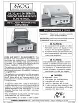
REGAL I DROP-IN
SERIES 34
OUTDOOR GAS BARBECUE
(Unit with optional backburner & oven shown)
DANGER
IF YOU SMELL GAS:
1. Shut off the gas to the appliance.
2. Extinguish any open fl ame.
3. Open lid if equipped with an oven.
4. If odor continues, keep away from the
appliance, and immediately call your gas
supplier or fi re department.
WARNING
1. Do not store or use gasoline, or other
fl ammable vapors and liquids, in the
vicinity of this or any other appliance.
2. A propane cylinder not connected for use
shall not be stored in the vicinity of this
or any other appliance.
Robert H. Peterson Co. • 14724 East Proctor Avenue • City of Industry, CA 91746
CODE AND SUPPLY REQUIREMENTS: This
barbecue must be installed in accordance with local
codes and ordinances or, in the absence of local
codes, with either the current National Fuel Gas
Code (ANSI Z223.1NFPA 54), Natural Gas and
Propane Installation Code (CSA B149), or Propane
Storage and Handling Code (CSA B149.2).
This appliance and its individual shutoff valves must
be disconnected from the gas supply piping system
when testing the system at pressures in excess of
½ psig (3.5 kPa).
This appliance must be isolated from the gas supply
piping system by closing its individual manual
shutoff valves during any pressure testing of the
gas supply system at pressures up to and including
½ psig (3.5 kPa).
Improper installation, adjustment, alteration,
service, or maintenance can cause injury or
property damage. Refer to this manual. For
assistance or additional information consult
a qualifi ed, professional installer, service
agency, or the gas supplier.
All electrical outlets in the vicinity of the barbecue
must be properly grounded in accordance with local
codes or, in the absence of local codes, with the
National Electrical Code, ANSI/NFPA 70, or the
Canadian Electrical Code, CSA C22.1, whichever
is applicable.
CAUTION: Keep all electrical supply cords and
fuel supply hoses away from any
heated surface.
Certifi ed to ANSI: Z21.58
WARNING

REV 3 - 1407091450
L-C2-005
TABLE OF CONTENTS
3
1 SAFETY WARNINGS & CODES
3 TABLE OF CONTENTS
5 PARTS LIST
6 FIRE MAGIC REGAL I DROP-IN SERIES (w/ BACKBURNER) PARTS LIST
7 FIRE MAGIC REGAL I DROP-IN BACKBURNER & OVEN PARTS LIST (WHERE FITTED)
8 MODEL SPECIFICATIONS
8 BUILT-IN GRILL DIMENSIONS TABLE
9 INSTALLATION REQUIREMENTS
10 ENSURING PROPER COMBUSTION AIR AND COOLING AIRFLOW
10 GAS-SUPPLY PLUMBING REQUIREMENTS
11 ENCLOSURE REQUIREMENTS
11 NATURAL GAS INSTALLS
11 PROPANE GAS INSTALLS (HOUSEHOLD & CYLINDER)
11 WHEN A PROPANE CYLINDER IS USED
13 SAFE USE & MAINTENANCE OF PROPANE GAS CYLINDERS
14 INSTALLATION
15 CHECKING AND CONVERTING GAS TYPE
15 CHECKING AND CONVERTING THE REGULATOR
16 CHECKING/CONVERTING THE BURNER ORIFICES
18 AIR SHUTTER ADJUSTMENT
18 MAIN BURNER AIR SHUTTER ADJUSTMENT
18 BACKBURNER AIR SHUTTER ADJUSTMENT
19 BARBECUE SAFETY INFORMATION & MAINTENANCE
19 DRIP COLLECTION SYSTEM
21 LIGHTING (IGNITION) INSTRUCTIONS
21 ELECTRONIC LIGHTING
21 MANUAL LIGHTING
22 ROTISSERIE INSTRUCTIONS
23 ACCESSORIES
24 CARE & CLEANING
25 TROUBLESHOOTING
25 REPLACING THE IGNITOR BATTERY
26 WARRANTY

REV 3 - 1407091450
L-C2-005
5
PARTS LIST
Replacement parts can be ordered
from your local Fire Magic dealer.
Item Description
1. TOP PANEL (STAINLESS STEEL)
or TOP PANEL (PORCELAIN)
2. 18"X10" COOKING GRID (STAINLESS STEEL)
or 18"X10" COOKING GRID (PORCELAINIZED CAST IRON)
3. FLAVOR GRID 7"
4. FLAVOR GRID 10" (2)
5. BURNER (6)
6. AIR SHUTTER SPRING (6)
7. AIR SHUTTER (6)
8. ORIFICE (NAT GAS)
or ORIFICE (PROPANE GAS)
9. VALVE MANIFOLD W/ VALVE & REGULATOR
10. BURNER MANIFOLD (3)
11. 15.5" FLEX TUBE ASSEMBLY
12. 34" FLEX TUBE ASSEMBLY
13. 48" FLEX TUBE ASSEMBLY
14. CONTROL KNOB (3)
15. IGNITOR ASSEMBLY
16. GROUND WIRE
17. ELECTRODE COLLECTOR ASSEMBLY
18. DRIP TRAY
19. DISPOSABLE DRIP TRAY LINER
1
15
5
7
8
10
6
11
12
13
9
17
14
16
3
4
18
19
2

REV 3 - 1407091450
L-C2-005
6
FIRE MAGIC REGAL I DROP-IN SERIES (w/ BACKBURNER) PARTS LIST
Item Description
1. OVEN HOOD W/ BACKBURNER (S.S. OR PORCELAIN)
2. BACKBURNER ASSEMBLY
3. TOP PANEL (STAINLESS STEEL)
or TOP PANEL (PORCELAIN)
4. 18"x10" COOKING GRID (PORCELAINIZED CAST IRON) (3)
or 18"X10" COOKING GRID (STAINLESS STEEL) (3)
5. FLAVOR GRID 7" (1)
6. FLAVOR GRID 10" (2)
7. BURNER (6)
8. AIR SHUTTER SPRING (6)
9. AIR SHUTTER (6)
10. ORIFICE (NAT GAS)
or ORIFICE (PROPANE GAS)
Item Description
11. BACKBURNER ORIFICE (NAT GAS)
or BACKBURNER ORIFICE (PROPANE GAS)
12. BURNER MANIFOLD (3)
13. VALVE MANIFOLD W/ VALVE & REGULATOR
14. 48" FLEX TUBE ASSEMBLY
15. 34" FLEX TUBE ASSEMBLY
16. 15.5" FLEX TUBE ASSEMBLY
17. ELECTRODE COLLECTOR ASSEMBLY
18. BACKBURNER KNOB (1)
19. CONTROL KNOB (3)
20. IGNITOR GENERATOR
21. DRIP TRAY
22. DISPOSABLE DRIP TRAY LINER
1
2
3
4
5
6
7
8
9
10
11
12
13
15
16
17
18
19
20
21
22
IMPORTANT
This Fire Magic oven
and backburner are fully
pre-assembled and tested at
the factory.
DO NOT attempt to remove
the oven and backburner
(optional) from the
barbecue prior to or during
installation or damage to
the connecting gas line and
ignitor wiring may occur.
The plastic straps that
secure the oven (optional)
to the barbecue unit must
be removed and discarded
prior to lighting.
14

REV 3 - 1407091450
L-C2-005
7
PAL NUT
OVEN
EL-34, ELBOW
& ORIFICE
IGNITOR
ELECTRODE
WIRE
FIRE MAGIC REGAL I DROP-IN BACKBURNER & OVEN PARTS LIST (WHERE FITTED)
PARTS INCLUDED WITH THE BACKBURNER ASSEMBLY ARE INSIDE THE BROKEN LINE
EXPLODED VIEW OF BACKBURNER ASSEMBLY
Important: Your Fire Magic barbecue,
oven and backburner (where
fi tted) are fully pre-assembled
and tested at the factory.
Do not attempt to remove the oven and backburner
from the barbecue prior to or during installation.
Damage to the connecting gas line and ignitor
wiring may occur.
The plastic straps that secure the oven to the
barbecue unit should be removed and discarded
prior to lighting.
Item
No.
Description
1. Rotisserie motor with
mounting bracket attached
2. Spit prongs
3. Handle
4.
Spit rod
5
/
8
" hex
5. Counterbalance
6. Spit bracket
Oven
Pal nut
El-34, elbow
& orifi ce
Ignitor
electrode
wire
or Orifice, NG
Backburner assembly
Screw, 10-32 x 3/8”,
stainless steel
Backburner cover
4199-69
Electrode double rod
w/electrode
Air shutter &
Adj. screw
3030-01
Backburner gas line
w/compression nuts
& sleeves
3730-02
Oven lid stop
bumper (pair)
3/4” Pal nut
4732-08
Mounting bracket
4732-09
Woodchip smoker tray
3/4” Pal nut
EL-34
Elbow (lid stop)
4732-07
Electrode
wire
Orifice, LP
5
4
1
3
6
Mounting
bracket
2

REV 3 - 1407091450
L-C2-005
8
Important: FOR YOUR SAFETY, you must provide openings in the island enclosure for drainage, replacement air, and
cross-ventilation of any storage area exposed to possible leakage from gas connections, the unit, or propane
bottles. See the ENCLOSURE REQUIREMENTS section for details.
An access panel/door is required to allow for ease of access to drip tray and all connections (right side of grill).
MODEL SPECIFICATIONS TABLE
Table 1
Main burner BTU per pair
N/P orifi ce drill size
22,000 x 3
#52/#61
Backburner BTU
†
N/P orifi ce drill size
22,000
#42/#54
Backburner Air Shutter
†
N/P
5
/8" gap
7
/16" gap
Optional Regal insulating liner model #
3270-50
A Countertop to unit bottom cut-out* 18"
B Side to side non-combustible cut-out* 41
1
/
2
"
C Front to back non-combustible cut-out* 20
1
/
2
"
*
If using an insulating liner consult liner instructions for counter cut-out dimensions.
†
If equipped
MODEL SPECIFICATIONS
STUB OUT GAS PIPE
ANYWHERE IN THIS AREA
BACK
5"
5"
41
1
/2"
C
B
Fig. 8-1
COUNTER TOP
REARFRONT
Gas stub
A
5"
Fig. 8-2
Model
Height Width Depth
(Top to bottom) (Left to right) (Front to back)
Hanger to top
(with oven)
Hanger to
hanger
(F)
Maximum
depth
(G)
Open
(D)
Closed
(E)
Regal I
20
3
/8" 15
1
/4" 45" 26
1
/2"
BUILT-IN GRILL DIMENSIONS TABLE
D
E
F
G
Fig. 8-3

REV 3 - 1407091450
L-C2-005
9
This grill is designed for outdoor use only. DO NOT use this grill
inside a building, garage, enclosed area, or under an unprotected
overhead combustible construction. See the EXHAUST REMOVAL
section on the following page for details on installing under a patio
roof. DO NOT use this grill in or on a recreational vehicle or boat.
Important: If installing this grill in a combustible surround,
the correct R.H. Peterson insulating liner must
be used.
Important: Refer to the information below to ensure all
required clearances are met.
The grill must have a minimum clearance of 18" from
combustible materials/items AT ALL TIMES.
For the minimum clearances between the grill and any side or rear
walls, your setup must fall within one (or more) of the following:
A. Clearance between grill and strictly non-combustible wall
(i.e. brick wall, see Fig. 9-1)
• The grill must have a minimum of 4" right, left, and rear
clearance from any non-combustible wall.
(To allow for proper ventilation and prevent dangerous
overheating.)
B. Clearance between grill and a protected combustible wall
(i.e. a non-combustible wall in front of a combustible wall to
serve as a barrier. This can be accomplished by brick, or
a metal stud fi nished with non-combustible substrate, see
Fig. 9-2)
• The grill must have a minimum of 14" right, left, and rear
clearance from the protected combustible wall.
(The 4" non-combustible material plus an additional 10"
clearance between the grill and protected wall.)
C. Clearance between grill and combustible wall
• The grill must have a minimum of 18" right, left, and rear
clearance from any combustible wall (see Fig. 9-3).
Backsplash (if applicable)
If a non-combustible backsplash exists, it must have a minimum
of a 4" clearance from the rear of the grill (to allow for proper
ventilation and prevent dangerous overheating). See Fig. 9-4.
Important: This 4" backsplash clearance must fi rst be met prior
to any non-combustible walls beginning behind it.
Fig. 9-1 Clearance 'A' Diagram
Fig. 9-2 Clearance 'B' Diagram
Fig. 9-3 Clearance 'C' Diagram
Non-combustible
Min.
4"
(Clearance required for
right, left, and rear)
Min.
14"
Non-combustible
substrate
Non-combustible 4"
Combustible
Min.
18"
(Clearance required for
right, left, and rear)
(Clearance required for
right, left, and rear)
Fig. 9-4 Backsplash clearance
Non-combustible
Backsplash
Min.
4"
Combustible
INSTALLATION REQUIREMENTS

REV 3 - 1407091450
L-C2-005
10
This is a drop-in type unit designed to fi t into countertop
enclosures. The top panel of the unit is removable for
gas hookup, servicing and burner adjustment.
The top panel MUST remain removable for servicing
(see PARTS LIST).
Note: This unit should be installed so that it can be
removed at a later date if factory service is
required. Any protrusion into the barbecue
enclosure may obstruct the frame and prevent
the unit from dropping into place (see GAS
SUPPLY PLUMBING REQUIREMENTS).
ENSURING PROPER COMBUSTION AIR AND
COOLING AIRFLOW
Proper airfl ow (Fig. 10-1) MUST be maintained for the
grill to perform as it was designed. If airfl ow is blocked,
overheating and poor combustion will result. Do not block
the air inlet around the inside edges of the top panel or
more than 75% of the cooking grid surface with pans
or griddles.
EXHAUST REMOVAL
If installed or used under a patio roof, the cooking grid
area must be fully covered by an exhaust hood with a
vent. An exhaust fan with a rating of 1,000 CFM (cubic
feet per minute) or more may be necessary to effectively
remove smoke and other cooking by-products from
the area under the hood. Fire Magic Vent Hoods are
available to meet this requirement. This grill must
not be used under unprotected overhead combustible
construction. THIS UNIT MUST NOT BE LOCATED IN
A FULLY ENCLOSED AREA OF ANY KIND.
GAS-SUPPLY PLUMBING REQUIREMENTS
For natural gas or a household propane system, rigid
1
/
2
" or
3
/
4
" black steel pipe or local code-approved pipe
is required to conduct the gas supply to the unit. Contact
your local gas supplier. Connect this pipe to a required
C.S.A.-approved stainless-steel fl ex connector. DO NOT
use a rubber hose within the grill enclosure. Apply
only joint compounds that are resistant to all gasses to
all male pipe fi ttings except fl are fi ttings. Make sure to
tighten every joint securely.
The gas supply pipe should enter from the fl oor, or
from the back or side wall in the right rear corner of
the barbecue enclosure, behind the valve control zone.
This pipe should terminate with a
1
/
2
" male pipe thread,
situated within 12" of the countertop and no more
than 5" from the back and side walls. See the MODEL
SPECIFICATIONS section for details.
Note: If
1
/
2
" pipe is used with natural gas, it should
be no longer than 20'.
Important: An external valve (with a removable
key) in the gas line is necessary for
safety when the grill is not in use. It also
provides for convenient maintenance.
CAUTION: Wind blowing into or across the rear
oven lid vent (if applicable) can cause
poor performance and/or dangerous
overheating. Orient the grill so that the
prevailing wind blows toward the front of
the grill.
GAS SUPPLY AND MANIFOLD PRESSURES:
For natural gas - normal 7" (17.78 cm) water column
(w.c.), minimum 5" (12.7 cm), maximum 10
1
/
2
" (26.7
cm). For propane gas - normal 11" w.c., minimum 10"
(25.4 cm), maximum 13" (33 cm).
INSTALLATION REQUIREMENTS (CONT.)
Fig. 10-1 - Ventilation Diagram
Vents at
Cylinder Le

REV 3 - 1407091450
L-C2-005
11
FOR YOUR SAFETY, you must provide the openings listed
below for drainage, replacement air, and cross-ventilation
of any storage area exposed to possible leakage from gas
connections, the unit, or propane cylinders.
One side of the enclosure can be left completely open to the
outside, OR 4 ventilation openings must be created:
NATURAL GAS INSTALLS
Two of the openings are to be at the top level (approx. 4"
below the countertop) and on opposite walls of the enclosure.
2 more openings must be at the fl oor level (no more than
5" above the fl oor) and on opposite sides of the enclosure.
Each opening must have a minimum of 10 sq. in. of free
area. To achieve the proper ventilation, you may drill a series
of holes, omit the grout from masonry joints, or replace a
brick with a hardware cloth screen. If the fl oor in the cabinet
is raised and the space beneath the cabinet is open to the
outside, the lower ventilation openings may be in the fl oor.
Reference Fig. 11-1.
PROPANE GAS INSTALLS
(HOUSEHOLD & CYLINDER)
Two of the openings are to be at the cylinder valve level
(approx. 16" above the fl oor) and on opposite walls of the
enclosure. 2 more openings must be at the fl oor level (no
more than 5" above the fl oor) and on opposite sides of the
enclosure. Each opening must have a minimum of 10 sq.
in. of free area. To achieve the proper ventilation, you may
drill a series of holes, omit the grout from masonry joints, or
replace a brick with a hardware cloth screen. If the fl oor in
the cabinet is raised and the space beneath the cabinet is
open to the outside, the lower ventilation openings may be
in the fl oor. Reference Fig. 11-1.
WHEN A PROPANE CYLINDER IS USED
When a propane cylinder is installed inside of the enclosure,
the guidelines below MUST be followed. FAILURE TO DO SO
MAY CAUSE DAMAGE TO YOUR UNIT AND/OR PERSONAL
INJURY. Reference Fig. 11-2 for an example.
• Only a C.S.A. listed stainless steel connector can be
connected to the grill.
• The regulator/hose assembly coming from the propane
cylinder can only be connected to the above mentioned
grill fl ex connector. DO NOT connect the regulator/
hose assembly directly to the grill. An adapter will
be required.
• A heatshield must be installed to protect the regulator/
hose assembly and propane cylinder valve.
• Fire Magic offers a propane cylinder door with tank
tray to meet the cylinder install requirements. See
Fig. 11-3.
Fig. 11-2 Propane cylinder orientation
Fig. 11-1 Ventilation detail
Nat. gas
installs
(repeat for
opposite
side)
Fig. 11-3 Optional Fire Magic door w/ tank tray
Adapter
L.P. gas
installs
(repeat for
opposite
side)
Grill
C.S.A. listed
stainless steel
fl ex connector
Heatshield
Regulator/
hose
assembly
L.P.
cylinder
Cylinder & regulator/
hose assembly
protected by heatshield
Equipped with
adapter for hose
assembly and
fl ex connector
ENCLOSURE REQUIREMENTS

13
U
L
Fig. 13-1 Type I Acme thread quick coupler
Pressure
relief
valve
QCC
Type 1
valve
Brass Acme
thread fi tting
Liquid level
indicator
(optional)
Hand nut with Acme
thread
Regulator
Vent
Hose
Hand wheel
The use of pliers or a wrench should not be necessary. Only
cylinders marked “propane” may be used.
To disconnect: Turn the hand nut counterclockwise until
detached (Fig. 13-1).
Important: Before using the unit, and after each time the
cylinder is removed and reattached, check
the hose for wear (see a.) and check all
connections for leaks. Turn off the unit valves
and open the main cylinder valve, then check
connections with soapy water. Repair any
leaks before lighting the unit.
CAUTION: Always turn the propane cylinder main valve
off after each use, and before moving the unit
and cylinder or disconnecting the coupling.
This valve must remain closed and the
cylinder disconnected while the appliance
is not in use, even though the gas fl ow is
stopped by a safety feature when the coupler
is disconnected.
Carefully inspect the hose assembly each time before the
gas is turned on. A cracked or frayed hose must be replaced
immediately.
If the appliance is stored indoors, the cylinder must be
disconnected and removed. Disconnected
cylinders must be
stored outdoors, out of the reach of children, with threaded
valve plugs tightly installed, and must not be stored in a
building, garage, or any other enclosed area.
FOR YOUR SAFETY
a. DO NOT store a spare propane-gas cylinder under or
near this appliance.
b. NEVER fi ll the cylinder beyond 80-percent full.
c. IF THE INFORMATION IN a. AND b. IS NOT FOLLOWED
EXACTLY, A FIRE CAUSING DEATH OR SERIOUS
INJURY MAY OCCUR.
IMPORTANT FOR YOUR SAFETY
READ AND FOLLOW ALL WARNINGS PROVIDED WITH THE PROPANE-GAS CYLINDER.
When operating this appliance with a propane-gas cylinder, these instructions and warnings MUST be observed.
FAILURE TO DO SO MAY RESULT IN A SERIOUS FIRE OR EXPLOSION.
CYLINDER/CONNECTOR REQUIREMENTS
a. Propane-gas cylinders, valves, and hoses must be
maintained in good condition and must be replaced if
there is visible damage to either the cylinder or valve. If the
hose is cut or shows excessive abrasion or wear, it must
be replaced before using the gas appliance (see e.).
b. This unit, when used with a cylinder, should be connected
to a standard 5-gallon (20 lb.) propane-gas cylinder
equipped with an OPD (Overfi ll Prevention Device).
The OPD has been required on all cylinders sold since
October 1,1998, to prevent overfi lling.
c. Cylinder dimensions should be approximately 12" (30.5
cm) in diameter and 18" (45.7 cm) high. Cylinders must
be constructed and marked in accordance with the
Specifi cations for Propane Gas Cylinders of the U.S.
Department of Transportation (D.O.T.) or the National
Standard of Canada, CAN/CSA-B339, Cylinders,
Spheres, and Tubes for Transportation of Dangerous
Goods.
d. The cylinder used must include a collar to protect the
cylinder valve, and the cylinder supply system must be
arranged for vapor withdrawal.
e. The pressure regulator and hose assembly (Fig. 13-1)
supplied with this outdoor gas appliance (L.P. models
only) must be used. Original and replacement pressure
regulator and hose assemblies must be those specifi ed
by the manufacturer for connection with a cylinder
connecting device identifi ed as Type I by the ANSI Z
21.58-2005/CGA 1.6-2005 (see PARTS LIST for ordering
information).
f. The propane-gas cylinder valve must be equipped with a
cylinder connection coupling device, described as Type I
in the standard defi ned in paragraph e. above. This device
is commonly described as an Acme thread quick coupler.
g. If the propane-gas cylinder comes with a dust plug, place
the dust cap on the cylinder valve outlet whenever the
cylinder is not in use.
QUICK COUPLER OPERATION
To connect the regulator/hose assembly to the propane-
gas cylinder valve fi tting: Press the hand nut on the regulator
over the Acme thread fi tting on the cylinder valve. Turn the hand
nut clockwise to engage the threads and tighten until snug.
e. The pressure regulator and hose assembly used must
match the specifi cation for Type I by ANSI Z 21.58-2005/
CGA 1.6-2005 (see Fig. 13-1).
For propane ventilation requirements, see the ENCLOSURE REQUIREMENTS section.
e. The pressure regulator and hose assembly (Fig. 13-1)
supplied with this outdoor gas appliance (select L.P.
models only) must be used. Original and replacement
pressure regulator and hose assemblies must be those
specified by the manufacturer for connection with a
cylinder connecting device identifi ed as Type I by the
ANSI Z 21.58-2005/CGA 1.6-2005 (see PARTS LIST for
ordering information).
SAFE USE & MAINTENANCE OF PROPANE GAS CYLINDERS

14
1. Make sure that your gas supply is turned OFF. Then connect the stainless steel fl ex connector to the gas
supply stub. Use pipe joint compound that is resistant to all gasses on the male pipe fi tting and tighten
securely. Do not use pipe joint compound to connect fl are fi ttings.
2. If you have not already done so, lower your barbecue into place, making sure not to pinch or kink the gas
connector.
3. Bring the fl ex connector up to the regulator found on the right side of the unit.
4. Connect the fl ex connector to the adapter on the regulator. Support the regulator adapter with a wrench
to avoid applying excessive torque to the assembly while tightening this connection securely. Do not use
pipe compound on the fl are fi tting.
5. Make sure the barbecue burner valves are in the OFF position. Turn the gas supply on. Then carefully
check all gas connections for leaks with a brush and soapy water before lighting. NEVER USE A MATCH
OR OPEN FLAME TO TEST FOR LEAKS.
6. Place a disposable liner in the provided drip tray. Hook the drip tray onto the two slots found on the right
side of the grill.
Note: Disposable liners (mini-loaf pans) are available at many stores. For your convenience, the drip pan
holder is designed so an empty 14 to 18 ounce (.41 lt to .53 lt) tin can may be substituted for the drip
pan and drip pan support.
7. Screw the two 1
1
/
4
" (2.8 cm) stabilizer screws (packed with the instructions) into the threaded inserts in
the right rear corner of the frame assembly. This will secure your barbecue in place.
8. If removed, replace the top panel. Be sure to reattach the ignitor wires. The top panel may be adjusted left
to right for bezel alignment with gas valve knobs.
9. If removed, replace the burner control knobs.
INSTALLATION
CONNECT THE GAS SUPPLY
For propane cylinders:
For connecting a propane unit to a portable propane tank, read the safety warnings and follow the instructions in
the section SAFE USE AND MAINTENANCE OF PROPANE GAS CYLINDERS.
Note: When a propane cylinder is installed inside of the enclosure, the guidelines found in the ENCLOSURE
REQUIREMENTS section MUST be followed.
For household propane or natural gas units:
CAUTION: Use only C.S.A. listed stainless-steel fl ex connectors within the enclosure.
WARNING
A rubber or plastic connector will rupture or leak, resulting in an explosion or serious injury if used
inside the appliance enclosure.
Installation can be completed by accessing the unit through the access panel on the right side of your enclosure.
Alternatively, the top panel may be removed (see CHECKING/CONVERTING THE BURNER ORIFICES section).

15
CHECKING AND CONVERTING GAS TYPE
This unit comes from the factory confi gured for one type
of gas, as marked on the label located behind the control
panel, or on the interior of the unit’s enclosure.
Converting this unit to burn a different type of gas
requires a conversion kit (contact your dealer for
details). The professional installer who converts this
unit to burn a different gas must perform the following
functions:
1. Change brass gas orifi ces (included at original shipping)
on each burner to match the new gas type (see
PRODUCT DATA TABLE, Table 1).
2. Switch the convertible gas regulator (if equipped) to
match the new gas type (see section below).
3. Plumb the unit as appropriate for the new gas supply.
4. Apply the label for the new gas (included at original
shipping) over the old gas information found on your
unit.
THIS APPLIANCE REGULATOR IS RATED FOR
1
/
2
PSI MAXIMUM. IF YOUR GAS SUPPLY IS
GREATER THAN
1
/
2
PSI, AN ADDITIONAL REGULATOR MUST BE INSTALLED TO REDUCE
THE INPUT PRESSURE TO THE UNIT to
1
/
2
PSI OR LESS. SEE GAS-SUPPLY REQUIREMENTS
SECTION FOR PROPER GAS-SUPPLY PRESSURE.
CHECKING AND CONVERTING THE REGULATOR
Note: Each end of the plastic converter is engraved with either the letters “NAT”
or “L.P.” (propane) for the respective gasses. When the converter is in the
cap and the cap is held uppermost, the letters seen indicate the gas that
the regulator is set up for.
To convert the regulator from one gas to another, follow steps 1-4.
STEP 2:
Remove the converter (the
plastic stalk) by carefully
pulling it away from the center
of the cap (it will snap out of
its seating).
STEP 1:
Unscrew and remove the cap from the
regulator, extracting the converter.
Regulator: note cap on top
STEP 3:
Turn the converter around and
replace it carefully, into the
center of the cap (it will snap
into place). Check that you can
read the type of gas the unit is
set for.
STEP 4:
Replace the unit into the
regulator and screw down
until snug.
Read gas
type here
WARNING
WARNING
HAZARDOUS OVERHEATING WILL OCCUR IF A
NATURAL-GAS ORIFICE IS USED WITH PROPANE
GAS. IF YOU ARE NOT SURE IF THE CORRECT
ORIFICES ARE INSTALLED, OR IF AN ORIFICE
CHANGE IS NECESSARY, REFER TO THE FOLLOWING
INSTRUCTIONS.
CAUTION: Make sure the unit is at a safe temperature
and isolated from gas and electrical
supplies before beginning the tasks
outlined below.
Note: The cooler the unit, the greater the tolerances
between the stainless-steel parts, and therefore
the easier to disassemble and reassemble
parts of the unit.
CAUTION: For your safety, exercise caution and
use adequate hand protection (such as
gloves) when handling potentially sharp
sheet-metal parts.

16
Important: Test the electrodes for spark before securing
the face to the frame (see also the section
REPLACING THE IGNITOR BATTERY).
9. Replace the face on the frame so the front lip of the face
covers the lip on the frame. Re-secure the face with the
face fastener screws.
10. Replace the control knobs.
11. Replace the fl avor grids and then the cooking grids so that
the cutout section of the grid is in front.
Important The oven and backburner (where fi tted) are
pre-installed at the factory and should not be
removed from the barbecue during installation.
BACKBURNER ORIFICE SIZE CHECKING/
CONVERSION
Before beginning, make sure you have the proper tools for
the task.
This task requires:
• a #2 Phillips-head screwdriver
• a #2 fl at-head screwdriver
• a
3
/
8
" wrench or socket screwdriver
Note: It may be necessary to remove the rotisserie rod
before beginning this procedure.
1. Remove the warming rack, if installed, and set it aside.
2. Remove the backburner cover, if installed.
3. Unscrew both backburner face plate screws using a
Phillips-head screwdriver and set them aside.
4. Remove the backburner face plate by pulling the bottom
toward the front of the barbecue and rotating it upward
and outward until the two top tabs can be removed from
the back wall of the barbecue. Set it aside.
5. Remove the backburner assembly anchoring screw on
the lower left of the backburner using a Phillips-head
screwdriver and set it aside.
CHECKING/CONVERTING THE BURNER ORIFICES
Fig. 16-2 Spark generator
CHECK FUEL ORIFICES FOR PROPER SIZE
1. Your Regal I barbecue is equipped with fuel orifi ces
for natural gas, unless otherwise indicated. To use
with propane gas, you must install smaller orifi ces to
avoid hazardous overheating. Refer to the MODEL
SPECIFICATIONS TABLE for the proper orifi ce size
needed.
2. Remove the cooking grids and fl avor grids from your
barbecue.
3. If the gas supply has been connected, make sure the
burner valves are in the OFF position. Then carefully pull
the valve knobs from their stems.
Note: Carefully, but fi rmly, lift the top panel away from the
frame. The spark generator for the ignition system
is attached to the top panel. The igniter need not
be detached, but the wires must be unplugged
from the generator before the panel is removed.
4. Using a fl at blade screwdriver, pry the burner retaining
clip from rear wall of the barbecue frame (see
Fig.16-1).
Remove the burner by; A) Pulling it to the front of the
barbecue; B) Lift the far end out of the notch; C) Pull the
burner away from the manifold, taking care not to lose
the air shutter and spring, which may become detached
when the burner is removed.
5. Using 3/8" socket, remove the orifi ce from the orifi ce
holder on the burner manifold and check the number
stamped on the face. Repeat for each burner as
necessary.
Note: If you have the optional backburner, check the
backburner orifi ce for size.
Note: The air shutter must be re-adjusted after removing
the burner to ensure proper combustion (see the
AIR SHUTTER ADJUSTMENT section).
6. Install the air shutter spring and the air shutter over the
orifi ce holder fi tting in the order and position shown in
Fig. 16-1. Carefully place the burner(s) back in position,
resting on the back fl ange of the inner liner so that the
brass orifi ce and orifi ce holder fi ttings project well into
the burners.
7. Replace all the burner hold down clips.
8. If you removed the top plate re-install the ignition wires.
Your barbecue may have either two (2) or four (4) wires
depending on the exact model. Pull the drip tray out. Lean
the face forward and plug the wires into the terminals on
the spark generator (Fig. 16-2). The wires can be plugged
into any terminal.
Fig. 16-1 - Burner orifi ce diagram
Burner
Burner neck
Spring
Burner manifold
Orifi ce
Inner liner
Air shutter
Hold down clip
Continued on next page

17
AIR SHUTTER
SCREW
CHECKING/CONVERTING THE BURNER ORIFICES (Cont.)
6. Pull the backburner assembly to the left, clear of the
orifi ce, and then rotate the top forward and downward
and lay it face down across the main burner dividers.
CAUTION: Be careful not to damage the wires
connected to the backburner assembly.
7. Use the socket driver to remove the exposed orifi ce
and replace it with the correct orifi ce for the gas to be
burned (see the MODEL SPECIFICATIONS TABLE
for correct orifi ce sizes, based on burner type and
gas type).
8. Replace the backburner assembly and re-insert the
anchoring screw. Center the backburner assembly
so that the backburner face place will fi t over it.
Tighten the anchoring screw using a Phillips-head
screwdriver.
9. While the backburner faceplate is still off, adjust the
backburner air shutter opening size by loosening
the air shutter adjustment screw with a fl at-head
screwdriver and sliding the air shutter to the position
indicated in the MODEL SPECIFICATIONS TABLE;
then re-tighten the adjustment screw. (see section
on AIR SHUTTER ADJUSTMENT).
10. Replace the backburner face plate by fi rst inserting
the upper tabs into the slots in the back wall of the
barbecue and then rotating the bottom downward
and inward.
11. Replace the two backburner faceplate screws using
a Phillips-head screwdriver.
Tip: Re-attaching the backburner faceplate may be
easier if the left screw is replaced before the right
screw.
THE BACKBURNER COVER
The backburner cover is installed by placing the curved
part of the cover over the top of the perforated portion
of the backburner (see
Fig. 17-2). The cover should be
kept in place on the backburner when it is not in use. This
will keep your backburner free from grease splatter and
debris that may hinder its performance.
Important: You must remove the backburner cover
before lighting the backburner.
Fig. 17-2
Ignitor wire
Orifice
Air
shutter
Electrode
Oven
(right side)
Air shutter
screw
IGNITOR WIRE
ELECTRODE
AIR
SHUTTER
AIR SHUTTER
SCREW
ORIFICE
OVEN
(RIGHT SIDE)
Fig. 17-1

18
MAIN BURNER AIR SHUTTER ADJUSTMENT
Important: The air shutters must be adjusted
after installation. If not, this appliance
may not light, heat evenly, or cook
properly.
Main burner air shutters are easily accessed by
removing the front panel (face). The air shutters are
located at the front of the burners behind the face
(see PARTS LIST). The air shutter has a small dimple
(see Fig.
18-1) that allows it to lock into notches in
the burner face. This prevents the air shutter from
moving.
WARNING
USE PROPERLY INSULATED TOOLS TO MAKE
THESE ADJUSTMENTS. NEVER TOUCH A
HOT BARBECUE DIRECTLY TO MAKE
ADJUSTMENTS.
AIR SHUTTER ADJUSTMENT
Partially open
Fig. 18-1
Closed
Fig. 18-2
Fig. 18-1 & Fig. 18-2 - Air shutter adjustment diagram
Flame on ports
Flame off ports
Ta b
(Turn tabs)
Dimple
Notch
1. Using the tip of a long screwdriver, close the air
shutters by turning the tabs to a vertical position
(Fig.
18-2).
2. Light the barbecue in accordance with the
LIGHTING INSTRUCTIONS and burn for two
minutes with the knobs on HI LIGHT and the
oven open.
3. After burning for two minutes, open the air
shutters, using the tip of a screwdriver, until
the fl ames lift off, or appear not to be touching
the burners (Fig.
18-1).
4. Begin closing the air shutters, with the tip of a
screwdriver, until the fl ames appear to burn while
touching the burner ports (Fig.
18-2).
Note: You may then see short yellow tips on the
fl ames. If fl ames are a lazy yellow, open the
air shutters until the fl ame is blue with yellow
tipping.
Note: Barbecues, in some installations, achieve a
better air/gas mixture and will ignite more
quickly if the valve is fi rst turned beyond HI
LIGHT to LOW for lighting.
BACKBURNER AIR SHUTTER ADJUSTMENT
Important: It is normal for the backburner to
smoke when it is burned for the fi rst
time. Burning your backburner on HI
LIGHT for approximately 15 minutes
will eliminate the smoking.
a. The air shutter on your backburner is preset at the
factory. However, due to atmospheric conditions
and different gas pressures, it may be necessary
to adjust the air shutter to obtain a proper burn.
b. First remove the backburner cover (if installed),
then loosen the air shutter screw (see Fig. 18-3).
It may be necessary to use pliers to turn the air
shutter. Light the backburner. With the control
knob on HI LIGHT adjust the air shutter to have
a blue fl ame that is not lifting off the burner (it
may also have slightly yellow tips).
c. Tighten the air shutter adjustment screw.
Fig. 18-3
Air shutter
screw
Main burner air shutters are easily accessed by
removing (when cool) the top panel (face). The air
shutters are controlled by the wire levers at the front
of the burners (see PARTS LIST). The air shutter has
a small dimple (see Fig.
18-1) that allows it to lock
into notches in the burner face. This prevents the air
shutter from moving.
WARNING
ONLY ADJUST 2 AIR SHUTTERS AND THEIR
CORRESPONDING BURNERS AT ONE TIME.
SHUT OFF THE BURNERS PRIOR TO MOVING ON
TO THE NEXT SET.
1. Using the wire levers, close the air shutters
by turning the tabs to a vertical position (Fig.
18-2).
2. Light the corresponding burner pair in accordance
with the LIGHTING INSTRUCTIONS and burn for
two minutes with the knob on HI LIGHT and the
oven open.
3. After burning for two minutes, open the air shutters
using the wire levers until the fl ames lift off, or
appear not to be touching the burners (Fig.
18-
1
).
4. Begin closing the air shutters with the wire levers
until the fl ames appear to burn while touching the
burner ports (Fig.
18-2).
Note: You may then see short yellow tips on the
fl ames. If fl ames are a lazy yellow, open the
air shutters until the fl ame is blue with yellow
tipping.
Note: Barbecues, in some installations, achieve
a better air/gas mixture and will ignite more
quickly if the valve is fi rst turned beyond HI
LIGHT to LOW for lighting.
5. Shut off the burners, then repeat for the next
set.

19
Each time you use the barbecue, make sure that:
1. The area around the barbecue is clear of fl ammable
vapors, liquids, and substances such as gasoline,
yard debris, wood, etc.
2. There is no blockage of the airfl ow through the vent
space located below the face of the unit.
3. When using propane gas:
a. The special ventilation openings in the enclosure
should be kept free and clear of debris
(see PLANNING THE LOCATION OF THE
BARBECUE).
b. If connected to a propane cylinder, the rubber
hose attached to the regulator should be carefully
inspected before each use.
c. The propane cylinder, regulator, and rubber hose should
be installed in a location not subject to heating above
125° F (51° C).
4. The burner fl ames burn evenly along both sides
of each burner with a steady flame, which is
mostly blue. (Refer to section on AIR SHUTTER
ADJUSTMENT.) A proper fl ame pattern will ensure
safe operation and optimal performance. Adjust
the air shutter as needed. If burner fl ames are not
normal, check the orifi ce and burner for insects or
insect nests.
5. The inline gas valve or gas cylinder valve is always
shut OFF when the barbecue is not in use.
6. The drip collector hole is clear and unobstructed.
Excessive grease deposits can result in a grease
fi re.
7. The barbecue is free and clear from combustible
materials, gasoline, and other fl ammable vapors
and liquids.
BARBECUE SAFETY INFORMATION & MAINTENANCE
WARNING
NEVER cover the entire cooking or grill surface with griddles or pans. Overheating will occur and
burners will not perform properly when combustion heat is trapped below the cooking surface.
CAUTION: NEVER spray water on a hot gas unit.
DRIP COLLECTION SYSTEM
The drip collector in this barbecue is part of the unit’s
main frame and is located below the burners. The drip
collector has slots that will allow excess drippings to
fall through during cooking, while separating the fi rebox
from the drip tray. Clean the drip tray after each use.
The drip collector allows you to brush or scrape residue
from the barbecue’s inner liner into the drip tray.
Following the manufacturers instructions and regular
cleaning of the barbecue’s interior with oven cleaner,
will help to prevent grease fi res.
Periodically check the burners to make sure they are
clear of debris. Properly adjusted burner fl ames burn
evenly along both sides of each burner with a steady
fl ame (mostly blue). If burner fl ames are not normal,
check the orifi ce and burner for insects or insect nests.
(See section on CHECKING/CONVERTING THE
BURNER ORIFICES for instructions on burner removal
and replacement.)
Check the burner ports at least annually for blockage by
removing the burner (see orifi ce changing instructions)
and visually inspect the gas intake tube for insects
and nests. A clogged tube can lead to a fi re beneath
the grill.

21
MANUAL LIGHTING
CAUTION: Always wait fi ve minutes for gas to clear
after any unsuccessful lighting attempt.
1. Follow steps 1 through 4 (left).
2. Insert either a burning long-barrel butane lighter,
a burning long-stem match, or a burning match
held by a wire extension holder (Fig.
21-2) through
the cooking grids to the burner (Fig. 21-3).
For backburners, hold the flame against the
perforated material of the backburner.
For sideburners, hold the fl ame against the burner.
3. While holding the match or lighter fl ame next to the
burner, depress the appropriate burner control knob
and turn it counterclockwise to the HI LIGHT position.
When the burner lights, remove the lighter or match.
4. If the burner does not light, IMMEDIATELY depress the
knob and turn the burner control knob to OFF. WAIT
FIVE MINUTES before repeating steps 2 through 4
of the MANUAL LIGHTING INSTRUCTIONS.
Note: Some installations achieve a better air/gas
mixture and may ignite quicker if the burner
control knob is fi rst turned beyond HI LIGHT
to LOW for lighting.
ELECTRONIC LIGHTING
1. Open all lids and remove all covers from the burners
you wish to light.
2. Turn all gas control knobs to their OFF positions.
3. Turn on the gas at its source.
Note: No matter which lighting method you use,
DO NOT turn
on the gas
to more than
one burner
at a time.
Adjacent grill
burners will
cross-ignite,
and gas
flow may be
restricted.
CAUTION: If the burners do not light within five
seconds, depress the control knob
and turn the knob to OFF. WAIT FIVE
MINUTES before repeating step 4. If you
smell gas, follow the instructions on the
cover of this manual. If the burners still do
not light after several attempts, refer to the
instructions for MANUAL LIGHTING.
4. Depress the control knob for the burner to be lit
and turn it to the HI LIGHT position, then press the
ignition button. Once the burner lights, release the
ignition button.
5. Repeat step 4 for each additional burner to be lit.
FOR PROPANE ONLY
Propane tanks are equipped with a safety shutdown
device that may cause low or no gas pressure/fl ame
at the burners if operating and lighting instructions
are not followed exactly (See important note in the
TROUBLESHOOTING section for more details.)
REMEMBER: FOR SAFE MANUAL LIGHTING, PLACE A
BURNING MATCH OR BUTANE LIGHTER BESIDE THE
BURNER - THEN TURN ON THE GAS (see Fig. 21-3).
Fig. 21-2 - Match holder
Read entire instructions before lighting, and follow these instructions each time you light the grill.
LIGHTING (IGNITION) INSTRUCTIONS
Fig. 21-3 - Manual lighting
Fig. 21-1 - Valve control knob
OFF
HI
LIGHT
LOW
TO
TURN OFF
TO TURN ON
Read setting
here
HIGH to
LIGHT
Read setting
here
TO TURN OFF
TO TURN ON
High to
light
SHUTTING OFF THE GRILL
To shut off the grill, push in each valve control knob and
turn it clockwise to the OFF position.
Always close the valve to the gas supply after each use
of the grill.

22
USING YOUR BACKBURNER AND
ROTISSERIE
Rotisserie cooking with the backburner is accomplished
without use of the main burners. Follow the steps in the
appropriate sections below to set up and use these
accessories (see PARTS LIST for image).
SET UP
1. Remove the backburner cover (if present) by sliding
it upward off the backburner.
2. Remove the cooking grids from your barbecue
(if necessary) to obtain maximum clearance for
larger cuts. The fl avor grids may also be removed if
required.
Tip: Aluminum foil or a baking pan may be placed
over the main burners to catch excess
drippings from cooking.
3. Attach the rotisserie motor to the rotisserie mounting
on the right side of your barbecue by inserting the
four mounting tabs through the four holes in the
motor mounting on the right side of the barbecue
and allowing the unit to slide downward and lock into
place.
Note: Make sure the motor is oriented so that no
rain can fall into the air vents.
4. Follow the LIGHTING INSTRUCTIONS to light the
backburner.
5. Allow the backburner to preheat for approximately
10 minutes on HI LIGHT setting.
PUTTING THE MEAT ON THE SPIT ROD
1. Slide the meat and spit prongs onto the spit rod so the
meat is centered and balanced as well as possible.
2. Tighten the spit prongs into place so that the meat
remains in a fi xed position on the rod and the meat
rotates with the rod.
Important: The counterbalance, which is included
with your rotisserie kit, should be used
to balance the load on your rotisserie
and prolong the life of your motor. Heavy
unbalanced meats can stress the rotisserie
motor and may cause motor failure.
USING THE COUNTERBALANCE SUPPLIED
WITH YOUR ROTISSERIE
1. Hold the spit rod at each end and lift. Do not grip
the rod. Let the rod rotate so the heavy side of the
meat hangs down naturally.
2. Turn the counterbalance on
the spit so the counterbalance
rod and weight point upward,
or opposite from the heavy
side of the meat. Tighten the
counterbalance rod in the hub
against a fl at surface of the spit
rod to secure (Fig. 22-1).
3. Loosen the thumb screw and
slide the weight along the
counterbalance rod to balance
the meat. Since meats are not
a uniform shape, it may not
be possible to achieve a perfect balance. Properly
balanced meat should not rotate when you hold the
spit rod loosely by the ends.
4. Make sure the counterbalance will not strike the
barbecue frame when the rotisserie is started.
RUNNING THE ROTISSERIE
1. Place the pointed end of the spit rod into the motor
drive socket and rest the handle end of the spit rod in
the spit bracket on the right side of the barbecue.
2. Plug in (if necessary) and turn on the rotisserie
motor.
3. Use a standard roasting guide to estimate the length
of time for your meat. A meat thermometer may also
be used to tell when your favorite cuts are cooked
to your liking. When testing temperatures with a
thermometer, turn off the rotisserie motor and turn
the backburner on LOW. This will keep the meat
from overcooking on one side.
Note: When burning properly, the backburner fl ames
will be blue with yellow tipping, and the grating
will glow red. The fi rst time it is used, the
backburner may smoke a little.
Important: Operate your backburner with the oven
closed. This simulates an oven effect and
helps your meat cook faster. Constant
rotation of the spit ensures even cooking
and maximum retention of juices.
Note: On large cuts of meat or whole turkeys, it
may be necessary to reduce the heat from
your backburner. Cooking your food at a lower
temperature for a longer period of time will
keep the outer surface from burning while
cooking the interior of your meat. In any case,
it is normal for the back burner grating to glow
red when operating properly.
Fig. 22-1
Thumb
screw
Tip: Aluminum foil or a baking pan may be placed
over the main burners, a little forward of
center, to catch excess drippings from the
meat.
3. Attach the rotisserie motor to the barbecue frame by
inserting the tab of the bracket attached to the motor
into the slot on the right of the barbecue so that the
spit rod will fi t into the motor drive socket from the left.
If left-side spit support is not already in place, insert
it into the tab on the left side of the barbecue at this
time.
ROTISSERIE INSTRUCTIONS

23
THE COOKING GRID LIFTER
Hold the grid lifter by gripping the center section with the
prongs pointing down (use an oven mitt or heavy glove
if the grill is hot). Insert the notched end of the grid lifter
into the cooking grid, in front of the midway point (front
to back; Fig. 23-3), and central (left to right; Fig. 23-4).
Twist the grill lifter (clockwise or counterclockwise) so
the handle is parallel to the grill rods. This “seats” the
spiked end of the grid lifter between two rods, enabling
you to safely lift out the grid. Lift slowly and adjust the
grid lifter, if necessary, for balance.
Placement of the grid lifter in cooking grid
Fig. 23-3
Fig. 23-4
THE DRIP TRAY
The drip collection system allows you to brush or scrape
excess dried residue from the grilling area directly into
the drip tray (see PARTS LIST for drip tray location).
THE GRILL BRUSH (OPTIONAL)
Purchase a Fire Magic
®
stainless-steel grill brush (sold
separately) to keep your grill cleaner. It comes with
scraper for large particles and a replaceable head with
brass bristles for overall cleaning.
Grill brush with replacement head
Fig. 23-1
THE WARMING RACK
The warming rack (Fig. 23-2) is packed separately.
To install the warming rack, lift the front of the rack
up slightly and insert the rack hangers into the two
holes in the back of the inner oven hood just above the
backburner. Then lower the front of the rack into a level
position to lock the rack in place.
To remove the warming rack, lift up on the front of the
rack until the rack hangers pull free from their supporting
holes.
Note: Removing the warming rack before using the
rotisserie will leave more clearance for the
meat being cooked.
Fig. 23-2 Warming rack in place inside oven
THE WARMING RACK (if equipped)
THE FLAVOR GRID(S)
Place each fl avor grid directly over a burner or burner
pair. Center each grid over the burner, oriented as
shown in Fig. 23-5.
Note: This allows heat from the burners to be evenly
distributed throughout the cooking area. The
fl avor grids heat and cool quickly, making the
grill very responsive to changes in heat from
the burners.
Fig. 23-5
WOOD CHIP SMOKER
Your optional backburner is supplied with a wood chip
box. The wood chip box is designed to sit on top of
the backburner assembly over the notch in the heat
defl ector (see Fig. 23-5). This box is designed to
be used when the backburner is in use. To use the
box, just dampen your favorite wood chips and put
them inside then set it in place. If you wish to refi ll
the wood chip box when it is hot, you may carefully
handle it using a pair of insulated pliers. You must
be very careful not to get burned.
Fig. 23-5
Wood chip (smoker) box
Cover
Fig. 23-6
in Fig. 23-6.
THE GRILL BRUSH (OPTIONAL)
Purchase a Fire Magic
®
stainless-steel grill brush (sold
separately) to keep your grill cleaner. It comes with
scraper for large particles and a replaceable head with
brass bristles for overall cleaning.
Grill brush with replacement head
ACCESSORIES

24
Fig. 24-1 - Wipe with grain
PROTECTING YOUR APPLIANCE FROM THE
WEATHER
An optional cover will protect your appliance when not
in use. (Allow to cool before covering.)
Please specify the model number and serial number
of your appliance when ordering a cover.
APPLIANCE MUST BE COMPLETELY COOL WHEN
CLEANING. DO NOT SPRAY ANY CLEANER OR
LIQUIDS ON THE APPLIANCE WHEN HOT.
The appliance must be cleaned as often as once a month
(depending on use) to prevent grease build-up and other
food deposits.
INTERIOR
THE BURNER PORTS MUST BE KEPT CLEAN TO
ENSURE PROPER IGNITION AND OPERATION.
Remove the burner (see orifi ce changing instructions)
and clean the ports and slots as required. Also inspect
and clean the burner inlet for insects and nests. A clogged
burner can lead to a fi re in the bottom of the appliance.
The inside of the appliance may be cleaned periodically
with oven cleaner if desired. Follow the oven cleaner
instructions for proper use.
Be careful not to get oven cleaner on the outside surface
of the appliance as it can permanently damage the fi nish.
EXTERIOR
Stainless steel surfaces when exposed to temperatures
produced by the grilling process will change color. The
stainless steel will change color from silver to brown
and blue. This can be removed by using stainless steel
cleaner.
Clean your appliance by fi rst using grill cleaner to remove
grease and dirt. Always wipe with the grain (See Fig.
24-1). Next, use stainless steel cleaner to restore the
stainless steel color (Note: not for mirror fi nish). Finish
by wiping your appliance down using polish wipes. To
clean any mirror fi nish (if applicable), use a quality
brand glass cleaner only, not any of the cleaners
mentioned above.
If your appliance is installed in a seaside (salt air) or
poolside (chlorine) location, it will be more susceptible
to corrosion and must be maintained/cleaned more
frequently. Do not store chemicals (such as chlorine or
fertilizer) near your stainless steel appliance.
Due to the nature of stainless steel, surface iron oxide
deposits may appear. Do not be alarmed – these deposits
are removable with stainless steel cleaner through prompt
and periodic maintenance. If not attended to promptly,
permanent pitting may occur.
By following these recommendations, you will enjoy the
beauty and convenience of your appliance for many years
to come.
IMPORTANT
IN THE EVENT OF A GREASE FIRE, IMMEDIATELY
SHUT OFF THE MAIN GAS VALVE TO THE GRILL.
KEEP THE LID OPEN AND ALLOW THE FIRE TO
EXTINGUISH ITSELF. A THOROUGH INSPECTION
BY A TRAINED SERVICE TECHNICIAN SHOULD
BE CONDUCTED BEFORE FUTURE USE OF YOUR
GRILL. THE SERVICE TECHNICIAN WILL CHECK
THE SYSTEM FOR GAS LEAKS AND WILL CHECK
ALL ELECTRICAL WIRING FOR DAMAGE. ALL GAS
LEAKS AND WIRING MUST BE REPAIRED PRIOR
TO FUTURE USE.
Wipe with grain
CARE & CLEANING
/