Page is loading ...

Application Report
SLVA595A–May 2013–Revised June 2013
Lead-Acid Charger and LED Driver using TPS5402
AdityaAmbardar
ABSTRACT
The TPS5402 device is a non-synchronous buck regulator with a wide operating range from 3.5 to 28 V.
The switching frequency of the converters can be set from 50 kHz to 1.1 MHz with an external resistor.
Frequency-spread spectrum operation is introduced for EMI reduction. TPS5402 supports pulse-skipping
mode to enhance the efficiency at light load, making this device an ideal pick for applications where
efficiencies at full load and light loads are a key concern.
This application note focuses on applications beyond the fixed voltage operation of the device, with
modification on the standard EVM board available for the part.
Two applications are demonstrated using the TPS5402 device:
1. Lead-acid battery charger
2. LED driver
Design is focused on simple methods to convert a constant voltage supply to constant current supply
using the TPS5402.
Contents
1 Lead-Acid Battery Charger ................................................................................................ 2
1.1 Modifications to the EVM: Feedback Loop ..................................................................... 2
1.2 Constant Current – Constant Voltage Charger ................................................................ 4
1.3 Results .............................................................................................................. 6
2 LED Driver Design .......................................................................................................... 7
2.1 Feedback Section .................................................................................................. 7
2.2 Results .............................................................................................................. 8
3 Conclusion ................................................................................................................... 8
4 References ................................................................................................................... 8
List of Figures
1 Linear Current Tapering Charger Using TPS5402 ..................................................................... 2
2 Charger Current, Current Sense Voltage and Feedback Voltage vs. V
OUT
(Battery Voltage)..................... 3
3 Linear Current Tapering Feedback Section ............................................................................. 3
4 Constant Current and Constant Voltage Charger Implementation using TPS5402................................ 4
5 Constant Current and Constant Voltage Charger Feedback Section................................................ 5
6 Feedback Pin Voltage Change vs. Charge Current, Showing 800 mV at 1.48 A .................................. 5
7 Feedback Voltage vs. Battery Voltage................................................................................... 6
8 Low Loss Implementation of Reverse Battery Connection Circuit using MOSFET ................................ 6
9 Bench Result of Charge Current vs. Battery Voltage using EVM Modification of TPS5402...................... 6
10 Efficiency Plot vs. Charge Current using EVM Modification of TPS5402............................................ 6
11 Simple LED Driver Implementation using TPS5402.................................................................... 7
12 Efficiency vs. Input Voltage for LED Driver using TPS5402........................................................... 8
1
SLVA595A–May 2013–Revised June 2013 Lead-Acid Charger and LED Driver using TPS5402
Submit Documentation Feedback
Copyright © 2013, Texas Instruments Incorporated

Vin = 16V- 28V
1
2
3
4 5
6
7
8
U1
TPS5402
1
1
2
2
L1 82uH
C1
0.1uF 50V
1
2
R1
R1210
0.2 Ohm
C2
10uF
C3
220uF/35V
C4
0.1uF
CA
D1
SB240
C5
220uF
C6
10uF
J1
Input +
J2
Input-
C8
2.2nF
1
2
R6
47k
C9
DNI 100pF
1
2
R8
100k
1
2
R2
2.2k
J3
BAT+
J4
BAT-
1
2
R3
33k
1
2
R4
13.3k
CA
D2 SB240
OUT IN(max) OUT
min
IN(max) Lripple% OUT SW
V (V V )
L
V I I f
´ -
=
´ ´ ´
Lead-Acid Battery Charger
www.ti.com
1 Lead-Acid Battery Charger
The TPS5402 device is used to charge the lead-acid batteries. Lead-acid batteries follow three stages of
charging: constant current, constant voltage (current tappers), and trickle.
With the TPS5402 device, a simple circuit is implemented to charge a lead-acid battery in constant current
and constant voltage mode. This circuit is designed to efficiently charge the small lead-acid-battery
chargers, which require charge currents up to 1.7 A. Two topologies of battery charging are discussed
below:
1. Linear current-tapering charger – lowest cost
2. Constant current – constant voltage charger
Specifications:
A 12-V lead-acid battery is used to test the design. The charger was designed considering the minimum
changes required on the standard TPS5402 EVM for the following specifications:
1. Battery charge voltage: 14.6 V
2. Charge current peak: 1.5 A
3. Input voltage: 16 – 28 V
max
4. Switching frequency: 270 kHz
Design:
The TPS5402 has an on-board resistance of 100 kΩ at R
osc
pin, which sets the frequency at 270 kHz. Set
the jumper to this option.
Below are the quick calculations for the minimum inductor value. For a detailed discussion on power stage
design, refer to the TPS5402 datasheet (SLVSBK4).
(1)
The I
Lripple
% for this application is 0.3 – 0.4, I
OUT
= 1.5 A, and the minimum inductor is around 76 µH. The
EVM has 82 µH which is sufficient for this design; the 82 µH creates lower ripple current than calculated in
the inductor.
Input capacitor and output capacitor selection were done using the equations in datasheet, and resulted in
component values close to the values present on the EVM.
1.1 Modifications to the EVM: Feedback Loop
Linear Current Tapering Charger – Lowest Cost
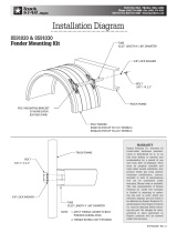
Figure 1. Linear Current Tapering Charger Using TPS5402
2
Lead-Acid Charger and LED Driver using TPS5402 SLVA595A–May 2013–Revised June 2013
Submit Documentation Feedback
Copyright © 2013, Texas Instruments Incorporated

ref
R4 || R2
V 10 V
R4 || R2 R3
R1
0.8 1.7
é ù
æ ö
- ´
ê ú
ç ÷
+
è ø
ë û
=
´
R1
R4
V R3R4
14.6 R4R2
V
R3R4 R2R4 R2R3 R3R4 R2R4 R2R3
´
´
= +
+ + + +
1
2
R1
R1210
0.2 Ohm
1
2
R2
2.2k
J3
BAT+
J4
BAT-
1
2
R3
33k
1
2
R4
13.3k
CA
D2 SB240
0.00
0.20
0.40
0.60
0.80
1.00
1.20
1.40
1.60
1.80
10 11 12 13 14 15
I Out and Voltage Scale
V Out
C002
I Charge
Vcsense
Vfb
www.ti.com
Lead-Acid Battery Charger
The circuit in Figure 1 shows a simple implementation of a battery charger. The charge current tapers off
as the battery voltage increases. Diode D2 protects the circuit in case the battery terminals are connected
in reverse and it reduces any leakage current from the battery to the circuit.
Resistance R3 and R4||R2 are designed for the maximum output voltage of 14.6 V, eventually charging
the battery to 14.3 V.
The V
fb
voltage due to the battery voltage and the current-sense voltage is plotted in the graph below (see
Figure 2).
Figure 2. Charger Current, Current Sense Voltage and Figure 3. Linear Current Tapering Feedback Section
Feedback Voltage vs. V
OUT
(Battery Voltage)
space
For an output voltage of 14.6 V and reference voltage of 0.8 V, choose R3 = 33 kΩ and R4||R2 = 1.88 kΩ.
Applying Kirchoff’s law, voltage at V
fb
node, the voltage across the R4 is actually given by Equation 2.
(2)
Choosing the voltage divide ratio of about 0.8 for the current sense voltage across R1, solving for the
second part of the equation, the results are:
R2 = 1.88k / 0.8 = 2.35 kΩ, choose 2.2 kΩ
R4 = 12.9 kΩ, choose 13 kΩ (3)
Current sense is calculated at a 12-V charging voltage or the user can choose the maximum current from
the converter at the worst-case battery voltage. This topology is best suited for applications where the
user cuts off the battery from the system well in advance, before the battery enters deep discharge
voltages of 9 V or below, or where the user wants to charge the battery at lower currents and at a higher
battery voltage, thus allowing a maximum current of about 1.7 A at 9 V. The worst-case battery voltage of
10.3 V, is assumed in this application note so:
• R1 = 0.19 Ω ~ 0.2 Ω (4)
Where V
ref
= 0.8 V feedback reference of TPS5402, 10 V is used in calculation, considering the 300-mV
drop of diode.
The above implementation ensures that feedback gets the appropriate offset voltage at 10.3-V battery
voltage, and does not overload the converter. A more rugged solution is discussed in Section 1.2.
3
SLVA595A–May 2013–Revised June 2013 Lead-Acid Charger and LED Driver using TPS5402
Submit Documentation Feedback
Copyright © 2013, Texas Instruments Incorporated

R3
R1 ref
V R2R7
V 0.361 V 0.694
R9R2 R9R7 R7R2
´
= ´ = -
+ +
2.5 R9R2
0.7 V
R9R2 R9R7 R7R2
´
=
+ +
R3
R1
fb
V R2R7
V R9R7
2.5 R9R2
V Volts
R9R2 R9R7 R7R2 R9R2 R9R7 R7R2 R9R2 R9R7 R7R2
´
´
´
= + +
+ + + + + +
Vin = 16V- 26V
1
2
3
4 5
6
7
8
U1
TPS5402
1
1
2
2
L1
82uH
C1
0.1uF 50V
R1
R1210
0.2 Ohm
C2
10uF
C3
220uF
C4
0.1uF
CA
D1
SB240
C5
220uF
C6
10uF
J1
Input +
J2
Input-
C8
2.2nF
R6
47k
C9
DNI 100pF
R8
100k
R2 15.4k
J3
BAT+
J4
BAT-
U2
TL431DBVR
R5
10k
R7
20k
D3
13V
R3
27
R4
91
R9
15.4K
D2
SB240
Lead-Acid Battery Charger
www.ti.com
1.2 Constant Current – Constant Voltage Charger
An offset to current-sense feedback is actually derived from a fixed reference voltage. Because the
reference voltage is set, the output voltage or battery voltage has no effect on the peak charging current of
the battery. The design is implemented with the consideration that the current tapers off or begins to taper
off before the battery voltage reaches approximately 13.4 V.
The schematic in Figure 4 shows the implementation of the constant current and constant voltage charger.
Figure 4. Constant Current and Constant Voltage Charger Implementation using TPS5402
Power stage components remain the same as in the previously discussed design. Note only the feedback
section is changed to keep the charge current independent of the battery voltage. The main purpose of
this change is to incorporate an external reference to keep the current sense resistance low and improve
the efficiency of the circuit.
The feedback consists of two components: a feedback-pin offset circuit consisting of the TL431 device for
current sense, and an overvoltage circuit consisting of Zener D3, R4 and R3. Equation 5 calculates the
feedback voltage, as seen on pin 5, which is compared to the internal 0.8 V used to regulate the power
stage.
(5)
Note that the TL431 device reference voltage is 2.5 V, the voltage across the current sense resistor is
V_R1 and is the voltage used for the overvoltage or constant voltage feedback is V_R3. Equation 5 is
written assuming R9 >> R3 and R2 >> R1, which in this case always holds true.
The first part of the equation is set so that 0.7 V is added through the TL431 device as shown in
Equation 6.
(6)
To design a sensing part, the user must watch for a momentary short of the Bat+ terminal at the current
sense resistors. This short creates a momentary surge at the sense pin. To keep the surge within limits
choose R2 = R9, creating approximately less than 0.4 ratio and simplifying Equation 3.
Choosing R7 = 20 kΩ, R2 = R9 = 15.55 kΩ, and choosing a standard value of 15.4 kΩ, results in a correct
value of Equation 4 at approximately 0.694 (see Equation 7).
(from Equation 6) (7)
4
Lead-Acid Charger and LED Driver using TPS5402 SLVA595A–May 2013–Revised June 2013
Submit Documentation Feedback
Copyright © 2013, Texas Instruments Incorporated

bat zener
V V
11 mA R4 R3 118
R4 R3
-
= Þ + = W
+
R3
R1 ref
V R2R7
V 0.361 V 0.694
R9R2 R9R7 R7R2
´
= ´ = -
+ +
R1
R1210
0.2 Ohm
C5
220uF
C6
10uF
R2 15.4k
J3
BAT+
J4
BAT-
U2
TL431DBVR
R5
10k
R7
20k
D3
13V
R3
27
R4
91
R9
15.4K
D2
SB240
0.00 500.00m 1.00 1.50
600.00m
900.00m
Vfb
Iout Charge Current = 1.48 A
Vfb = 800 mV
Iout Charge Current
www.ti.com
Lead-Acid Battery Charger
Note that V
R3
is not considered at this stage because it adds voltage only after the Zener starts
conducting.
V
R1
= 0.293 V
Now designing for I
OUT
of 1.5 A, R
1
= 0.195 Ω. Choose a standard value resistance of 0.2 Ω. The graph in
Figure 6 shows the variation of the feedback voltage with the current through the sense resistor.
Figure 5. Constant Current and Constant Voltage Figure 6. Feedback Pin Voltage Change vs. Charge
Charger Feedback Section Current, Showing 800 mV at 1.48 A
space
For the output constant voltage section, use the Zener diode D3 of 13 V. The purpose is to measure 14.3
V across the battery and add the remaining 0.1 V to the feedback voltage, just like in the current sense
section (see Equation 8).
(from Equation 6)
• V
R3
= 0.293 V at 14.3 V (8)
The Zener diode 13-V current for this calculation is around 11 mA as implied in Equation 9.
where
• R3 = 0.293 / 0.01 = 26.6 Ω, choosing 27 Ω, R4 = 91 Ω (9)
5
SLVA595A–May 2013–Revised June 2013 Lead-Acid Charger and LED Driver using TPS5402
Submit Documentation Feedback
Copyright © 2013, Texas Instruments Incorporated

0
0.2
0.4
0.6
0.8
1
1.2
1.4
1.6
1.8
2
9.9 10.9 11.9 12.9 13.9 14.9 15.9
I Charge Current
VBAT
C009
70
75
80
85
90
95
100
0.0 0.5 1.0 1.5 2.0
Effeciency (%)
I Charge Current
C010
CSD17313Q2
RG1 10k
RG2 10k
Vout+
Bat+
Bat-
R1 200m
8.00
600.00m
900.00m
Vfb
Battery Voltage = 14.32
Vfb = 800 mV
Battery Voltage V
9.00 10.00 11.00 12.00
13.00
14.00
Lead-Acid Battery Charger
www.ti.com
The following relationship between V
fb
and battery voltage is shown in Figure 7.
Figure 7. Feedback Voltage vs. Battery Voltage Figure 8. Low Loss Implementation of Reverse Battery
Connection Circuit using MOSFET
The user is able to also remove the D2 and use a MOSFET in the configuration shown in Figure 8 to
improve efficiency. A lower R
dson
MOSFET ensures better efficiencies at higher charge currents.
1.3 Results
The circuit was tested in the lab with a slight modification to charge the battery to 14.8 V. A lower Zener
voltage of 13.3 V causes the current to taper early at approximately 12 V (see Figure 7). This taper
voltage changes by using a Zener voltage close to the cut-off voltage and choosing the R4 and R3
resistance according to Equation 9.
Figure 9 shows the constant-current behavior of the design, and that the current reaches zero when the
battery charges to 14.8 V.
Figure 9. Bench Result of Charge Current vs. Battery Figure 10. Efficiency Plot vs. Charge Current using
Voltage using EVM Modification of TPS5402 EVM Modification of TPS5402
Efficiency measurements were performed at 16-V input voltage and at the battery terminals before the D2
diode, so diode power loss was not considered (see Figure 10). The efficiency stayed above 91%
throughout the operation, mostly at 95%, until the battery entered a sub 100-mA charge current range,
where the efficiency was measured at 86% with a 70-mA charge current.
6
Lead-Acid Charger and LED Driver using TPS5402 SLVA595A–May 2013–Revised June 2013
Submit Documentation Feedback
Copyright © 2013, Texas Instruments Incorporated

( ) ( )
R1 led
0.8 0.6 R3R4 R2R4 R2R3
V 0.263 V I R1
R3R4
- ´ + +
= = = ´
9.9 R4R2
0.6
R3R4 R2R4 R2R3
´
=
+ +
R1
R4
V R3R4
9.9 R4R2
V
R3R4 R2R4 R2R3 R3R4 R2R4 R2R3
´
´
= +
+ + + +
www.ti.com
LED Driver Design
2 LED Driver Design
The TPS5402 device, as discussed in the above battery charge configuration, is used in the below
configuration to drive LEDs.
A simple LED-driver design is designed with the specifications below:
1. LED voltage 3.3-V LEDs and three in series: 9.9 V
2. LED current : 0.5 A
3. Input voltage: 10 – 28 V
max
4. Switching frequency: 270 kHz
Again, with minimum changes to the EVM and using Equation 1: L = 150 µH. The inductor is unchanged
at 82 µH, which results in higher ripple current in the inductor. Note that for improved performance,
change the inductor for the reference design on the board.
Keeping the power section the same without changing the input, output capacitors, and compensation
values, the schematic is shown in Figure 11.
Figure 11. Simple LED Driver Implementation using TPS5402
2.1 Feedback Section
For feedback design, use Equation 2, and change the values of output voltage to 9 V:
(10)
Choose a reference offset from output around 0.6 V:
(11)
Using R3 = 33 kΩ, and using R4 || R2 as a standard value of 2.13 kΩ.
Keeping the ratio R2 / (R2 + R4) = 0.8 (approximately) in calculations, to create a smaller sense
resistance and to lower the conduction loss, use R4 = 10 kΩ, and R2 = 2.7 kΩ as standard values. The
actual ratio value is given by Equation 9, resulting in Equation 12.
(12)
Solving for a 0.5-A current, R1 = 0.526 Ω, choose R1 = 0.5 Ω.
7
SLVA595A–May 2013–Revised June 2013 Lead-Acid Charger and LED Driver using TPS5402
Submit Documentation Feedback
Copyright © 2013, Texas Instruments Incorporated

70
75
80
85
90
95
100
9 14 19 24 29
Effeciency (%)
Input Voltage (V)
C012
Conclusion
www.ti.com
Because the switch current for the internal MOSFET of the TPS5402 device is 2.2 A, the user can design
LED drivers up to 1.7-A of continuous current for specific input and output voltages.
2.2 Results
The efficiency versus input voltage for the schematic in Figure 11 is shown in Figure 12.
Figure 12. Efficiency vs. Input Voltage for LED Driver using TPS5402
The efficiency for the design is above 90% at a higher voltage of 28 V, and at a lower voltage of 10 V, the
efficiency is approximately 93%.
3 Conclusion
The TPS5402 device works in constant current for lead-acid-charging and LED-driver applications. The
methods to achieve high efficiencies by altering the feedback sections are discussed in this application
note. As observed in this application note, the TPS5402 device shows high efficiency characteristics.
4 References
1. TPS5402 Data Sheet (SLVSBK4)
2. TPS5402 EVM User’s Guide (SLVU775)
3. Understanding Buck Power Stages in Switch Mode Power Supplier (SLVA057)
8
Lead-Acid Charger and LED Driver using TPS5402 SLVA595A–May 2013–Revised June 2013
Submit Documentation Feedback
Copyright © 2013, Texas Instruments Incorporated

IMPORTANT NOTICE
Texas Instruments Incorporated and its subsidiaries (TI) reserve the right to make corrections, enhancements, improvements and other
changes to its semiconductor products and services per JESD46, latest issue, and to discontinue any product or service per JESD48, latest
issue. Buyers should obtain the latest relevant information before placing orders and should verify that such information is current and
complete. All semiconductor products (also referred to herein as “components”) are sold subject to TI’s terms and conditions of sale
supplied at the time of order acknowledgment.
TI warrants performance of its components to the specifications applicable at the time of sale, in accordance with the warranty in TI’s terms
and conditions of sale of semiconductor products. Testing and other quality control techniques are used to the extent TI deems necessary
to support this warranty. Except where mandated by applicable law, testing of all parameters of each component is not necessarily
performed.
TI assumes no liability for applications assistance or the design of Buyers’ products. Buyers are responsible for their products and
applications using TI components. To minimize the risks associated with Buyers’ products and applications, Buyers should provide
adequate design and operating safeguards.
TI does not warrant or represent that any license, either express or implied, is granted under any patent right, copyright, mask work right, or
other intellectual property right relating to any combination, machine, or process in which TI components or services are used. Information
published by TI regarding third-party products or services does not constitute a license to use such products or services or a warranty or
endorsement thereof. Use of such information may require a license from a third party under the patents or other intellectual property of the
third party, or a license from TI under the patents or other intellectual property of TI.
Reproduction of significant portions of TI information in TI data books or data sheets is permissible only if reproduction is without alteration
and is accompanied by all associated warranties, conditions, limitations, and notices. TI is not responsible or liable for such altered
documentation. Information of third parties may be subject to additional restrictions.
Resale of TI components or services with statements different from or beyond the parameters stated by TI for that component or service
voids all express and any implied warranties for the associated TI component or service and is an unfair and deceptive business practice.
TI is not responsible or liable for any such statements.
Buyer acknowledges and agrees that it is solely responsible for compliance with all legal, regulatory and safety-related requirements
concerning its products, and any use of TI components in its applications, notwithstanding any applications-related information or support
that may be provided by TI. Buyer represents and agrees that it has all the necessary expertise to create and implement safeguards which
anticipate dangerous consequences of failures, monitor failures and their consequences, lessen the likelihood of failures that might cause
harm and take appropriate remedial actions. Buyer will fully indemnify TI and its representatives against any damages arising out of the use
of any TI components in safety-critical applications.
In some cases, TI components may be promoted specifically to facilitate safety-related applications. With such components, TI’s goal is to
help enable customers to design and create their own end-product solutions that meet applicable functional safety standards and
requirements. Nonetheless, such components are subject to these terms.
No TI components are authorized for use in FDA Class III (or similar life-critical medical equipment) unless authorized officers of the parties
have executed a special agreement specifically governing such use.
Only those TI components which TI has specifically designated as military grade or “enhanced plastic” are designed and intended for use in
military/aerospace applications or environments. Buyer acknowledges and agrees that any military or aerospace use of TI components
which have not been so designated is solely at the Buyer's risk, and that Buyer is solely responsible for compliance with all legal and
regulatory requirements in connection with such use.
TI has specifically designated certain components as meeting ISO/TS16949 requirements, mainly for automotive use. In any case of use of
non-designated products, TI will not be responsible for any failure to meet ISO/TS16949.
Products Applications
Audio www.ti.com/audio Automotive and Transportation www.ti.com/automotive
Amplifiers amplifier.ti.com Communications and Telecom www.ti.com/communications
Data Converters dataconverter.ti.com Computers and Peripherals www.ti.com/computers
DLP® Products www.dlp.com Consumer Electronics www.ti.com/consumer-apps
DSP dsp.ti.com Energy and Lighting www.ti.com/energy
Clocks and Timers www.ti.com/clocks Industrial www.ti.com/industrial
Interface interface.ti.com Medical www.ti.com/medical
Logic logic.ti.com Security www.ti.com/security
Power Mgmt power.ti.com Space, Avionics and Defense www.ti.com/space-avionics-defense
Microcontrollers microcontroller.ti.com Video and Imaging www.ti.com/video
RFID www.ti-rfid.com
OMAP Applications Processors www.ti.com/omap TI E2E Community e2e.ti.com
Wireless Connectivity www.ti.com/wirelessconnectivity
Mailing Address: Texas Instruments, Post Office Box 655303, Dallas, Texas 75265
Copyright © 2013, Texas Instruments Incorporated
/