Pioneer AVH-190DVD Owner's manual

Category
Subwoofers
Type
Owner's manual

This manual is also suitable for

2
Precautions
Your new product and this manual
Do not operate this product, any applications, or the rear
view camera option (if purchased) if doing so will divert your
attention in any way from the safe operation of your vehicle.
Always observe safe driving rules and follow all existing
traffic regulations. If you experience difficulty in operating
this product or reading the display, park your vehicle in a
safe location and apply the handbrake before making the
necessary adjustments.
Do not install this product where it may (i) obstruct the driv-
er’s vision, (ii) impair the performance of any of the vehicle’s
operating systems of safety features, including airbags, haz-
ard lamp buttons, or (iii) impair the driver’s ability to safely
operate the vehicle. In some cases, it may not be possible to
install this product because of the vehicle type or the shape
of the vehicle interior.
The graphical symbol
placed on the product means
direct current.
Important safeguards
WARNING
Pioneer does not recommend that you install this
product yourself. This product is designed for
professional installation only. We recommend that only
authorised Pioneer service personnel, who have special
training and experience in mobile electronics, set up and
install this product. NEVER SERVICE THIS PRODUCT
YOURSELF. Installing or servicing this product and its
connecting cables may expose you to the risk of electric
shock or other hazards, and can cause damage to this
product that is not covered by warranty.
Precautions before connecting
the system
WARNING
Do not take any steps to tamper with or disable the
handbrake interlock system which is in place for your
protection. Tampering with or disabling the handbrake
interlock system could result in serious injury or death.
CAUTION
Secure all wiring with cable clamps or electrical tape.
Do not allow any bare wiring to remain exposed.
Do not directly connect the yellow lead of this product
to the vehicle battery. If the lead is directly connected
to the battery, engine vibration may eventually cause
the insulation to fail at the point where the wire
passes from the passenger compartment into the
engine compartment. If the yellow lead’s insulation
tears as a result of contact with metal parts, short-
circuiting can occur, resulting in considerable danger.
It is extremely dangerous to allow cables to become
wound around the steering column or gearstick. Be
sure to install this product, its cables, and wiring
away in such so that they will not obstruct or hinder
driving.
Make sure that the cables and wires will not interfere
with or become caught in any of the vehicle’s moving
parts, especially the steering wheel, gearstick,
handbrake, sliding seat tracks, doors, or any of the
vehicle’s controls.
Do not route wires where they will be exposed to
high temperatures. If the insulation heats up, wires
may become damaged, resulting in a short circuit or
malfunction and permanent damage to the product.
Do not shorten any leads. If you do, the protection
circuit (fuse holder, fuse resistor or filter, etc.) may
fail to work properly.
Never feed power to other electronic products by
cutting the insulation of the power supply lead of
this product and tapping into the lead. The current
capacity of the lead will be exceeded, causing
overheating.
Before installing this product
Use this unit with a 12-volt battery and negative earthing
only. Failure to do so may result in a fire or malfunction.
To avoid shorts in the electrical system, be sure to discon-
nect the (–) battery cable before installation.
To prevent damage
WARNING
Use speakers over 50 W (output value) and between
4Ωto8Ω(impedancevalue).Donotuse1Ωto3Ω
speakers for this unit.
The black lead is earth. Please earth this lead
separately from the earth of high-current products
such as power amps. Do not earth more than one
product together with the earth from another product.
For example, you must separately earth any amp
unit away from the earth of this product. Connecting
earths together can cause a fire and/or damage the
products if their earths became detached.
When replacing the fuse, be sure to only use a fuse of
the rating prescribed on this product.
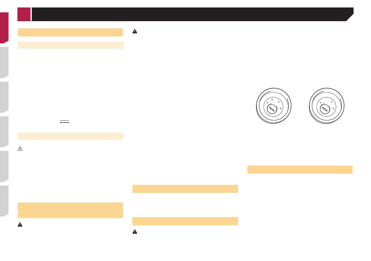
This product cannot be installed in a vehicle without ACC
(accessory) position on the ignition switch.
A
C
C
O
N
S
T
A
R
T
O
F
F
O
N
S
T
A
R
T
O
F
F
ACC position No ACC position
To avoid short-circuiting, cover the disconnected lead with
insulating tape. It is especially important to insulate all
unused speaker leads, which if left uncovered may cause a
short circuit.
For connecting a power amp or other devices to this product,
refer to the manual for the product to be connected.
Notice for the blue/white lead
When the ignition switch is turned on (ACC ON), a control
signal is output through the blue/white lead. Connect to an
external power amp’s system remote control terminal, the
auto-aerial relay control terminal, or the aerial booster power
control terminal (max. 300 mA 12 V DC). The control signal is
output through the blue/white lead, even if the audio source
is switched off.
Connection
< QRD3468-A >
Connection
3
This product
1
2
345678
1 Microphone 3 m
(AVH-290BT)
2 This product
3 Aerial jack
4 Wired remote input
Hard-wired remote control adapter can be connected (sold
separately).
5 Power supply
6 Fuse (10 A)
7 Front output
8 Rear output or subwoofer output
Power cord
1. 2.
1
3
2*
2
4
1*
5
4*
6
3*
b (6*)
8
9
a (5*)
7
c
d
e
f
kj
g
i
h
1 To power supply
2 Depending on the kind of vehicle, the function of 2* and 4*
may be different. In this case, be sure to connect 1* to 4*
and 3* to 2*.
3 Yellow (2*)
Back-up (or accessory)
4 Yellow (1*)
Connect to the constant 12 V supply terminal.
5 Red (4*)
Accessory (or back-up)
6 Red (3*)
Connect to terminal controlled by ignition switch (12 V DC).
7 Connect leads of the same colour to each other.
8 Orange/white
To lighting switch terminal.
9 Black (earth)
To vehicle (metal) body.
a Blue/white (5*)
The pin position of the ISO connector will differ depending
on the type of vehicle. Connect 5* and 6* when Pin 5 is an
aerial control type. In another type of vehicle, never connect
5* and 6*.
b Blue/white (6*)
Connect to auto-aerial relay control terminal (max. 300 mA
12 V DC).
c Blue/white
Connect to system control terminal of the power amp (max.
300 mA 12 V DC).
d Violet/white
Of the two lead wires connected to the back lamp, connect
the one in which the voltage changes when the gear shift
is in the REVERSE (R) position. This connection enables
the unit to sense whether the car is moving forwardss or
backwardss.
e Light green
Used to detect the ON/OFF status of the handbrake. This
lead must be connected to the power supply side of the
handbrake switch.
f Connection method
1 Clamp the lead.
2 Clamp firmly with needle-nosed pliers.
g Power supply side
h Handbrake switch
i Earth side
j Speaker leads
White: Front left +
White/black: Front left –
Grey: Front right +
Grey/black: Front right –
Green: Rear left +
Green/black: Rear left –
< QRD3468-A >
Connection
4
Violet: Rear right +
Violet/black: Rear right –
k ISO connector
In some vehicles, the ISO connector may be divided into two.
In this case, be sure to connect to both connectors.
The position of the handbrake switch depends on the vehicle
model. For details, consult the vehicle Owner’s Manual or
dealer.
When a subwoofer is connected to this product instead of
a rear speaker, change the rear output setting in the initial
setting. The subwoofer output of this product is monaural.
Whenusingasubwooferof70W(2Ω),besuretoconnect
the subwoofer to the violet and violet/black leads of this unit.
Do not connect anything to the green and green/black leads.
Parking Brake
1 If“Lightgreen”cableisconnectedtohand-
brake switch, video image on the display will
be controlled by this function.
2 The monitor displays the black screen with
warning information to prevent the driver
watching video contents during driving.
Power amp (sold separately)
Without internal amp
Important
The speaker leads are not used when this connection is in
use.
1
3
2
4
3
6
55
77
2
1
With internal amp
Important
Front speaker and Rear speaker signals are output from the
speaker leads when this connection is in use.
1
3
2
4
88
1 System remote control
Connect to Blue/white cable.
2 Power amp (sold separately)
3 Connect with RCA cable (sold separately)
4 To Rear or subwoofer output
Connect a cable according to the preout setting.
5 Rear speaker or subwoofer
6 To Front output
7 Front speaker
8 Subwoofer
You can change the RCA output of the subwoofer depending
on your subwoofer system.
The subwoofer output of this product is monaural.
iPod / iPhone
For details on how to connect an external device using a
separately sold cable, refer to the manual for the cable.
For details concerning the connection, operations and
compatibility of iPhone, refer to Operation Manual.
iPod / iPhone with Lightning
connector
Connecting via the USB port
The USB interface cable for iPod / iPhone (CD-IU52) (sold sepa-
rately) is required for the connection.
1
2
4
3
1 USB port
2 USB cable 1.5 m
3 USB interface cable for iPod / iPhone (CD-IU52) (sold
separately)
4 iPhone with Lightning connector
iPod / iPhone with 30-pin
connector
Connecting via the AUX input
The USB interface cable for iPod / iPhone (CD-IU201V) (sold
separately) is required for the connection.
1
2
5
3
4
1 USB port
2 AUX input
3 USB cable 1.5 m
4 USB interface cable for iPod / iPhone (CD-IU201V) (sold
separately)
5 iPhone with 30-pin connector
< QRD3468-A >
Connection
5
Camera
About rear view camera
When you use the rear view camera, the rear view image is
automatically switched from the video by moving the gearstick
to REVERSE (R). Camera View mode also allows you to check
what is behind you while driving.
WARNING
USE INPUT ONLY FOR REVERSE OR MIRROR IMAGE REAR
VIEW CAMERA. OTHER USE MAY RESULT IN INJURY OR
DAMAGE.
CAUTION
The screen image may appear reversed.
With the rear view camera you can keep an eye on
trailers, or back into a tight parking spot. Do not use for
entertainment purposes.
Objects in rear view may appear closer or more distant
than in reality.
The image area of full-screen images displayed while
backing or checking the rear of the vehicle may differ
slightly.
1
2
3
4
56
7
8
1 Rear view camera (ND-BC8) (sold separately)
2 To video output
3 RCA cable (supplied with ND-BC8)
4 This product
5 Brown (R.C IN)
6 Power supply
7 Power cord
8 Violet/white (REVERSE-GEAR SIGNAL INPUT)
Power cord on page 3
Connect only the rear view camera to R.C IN. Do not connect
any other equipment.
Some appropriate settings are required to use rear view
cameras.
For details, refer to Operation Manual.
External video component and
the display
1
2
3
6
7
89
3
a b
c d
e
5
4
1 Rear display with RCA input jacks
2 To video input
3 RCA cables (sold separately)
4 This product
5 Yellow (V OUT)
6 AUX input
7 Mini-jack AV cable (CD-RM10) (sold separately)
8 Yellow
9 Red, white
a To Yellow
b To Red, white
c To video output
d To audio outputs
e External video component (sold separately)
The appropriate setting is required to use the external video
component.
For details, refer to Operation Manual.
WARNING
NEVER install the rear display in a location that enables
the driver to watch the video source while driving.
This product’s rear video output is for connection of a display
to enable passengers in the rear seats to watch the video
source.
< QRD3468-A >
Connection
6
Precautions before installation
CAUTION
Never install this product in places where, or in a manner
that:
Could injure the driver or passengers if the vehicle
stops suddenly.
May interfere with the driver’s operation of the
vehicle, such as on the floor in front of the driver’s
seat, or close to the steering wheel or gearstick.
To ensure proper installation, be sure to use the
supplied parts in the manner specified. If any parts
are not supplied with this product, use compatible
parts in the manner specified after you have the parts’
compatibility checked by your dealer. If parts other
than supplied or compatible ones are used, they may
damage internal parts of this product or they may
work loose and the product may become detached.
Do not install this product where it may (i) obstruct
the driver’s vision, (ii) impair the performance of any
of the vehicle’s operating systems or safety features,
including airbags, hazard lamp buttons or (iii) impair
the driver’s ability to safely operate the vehicle.
Never install this product in front of or next to the
place in the dashboard, door, or pillar from which one
of your vehicle’s airbags would deploy. Please refer
to your vehicle’s owner’s manual for reference to the
deployment area of the frontal airbags.
Before installing
Consult with your nearest dealer if installation requires
drilling holes or other modifications of the vehicle.
Before making a final installation of this product, temporarily
connect the wiring to confirm that the connections are
correct and the system works properly.
Installation notes
Do not install this product in places subject to high tempera-
tures or humidity, such as:
Places close to a heater, vent or air conditioner.
Places exposed to direct sunlight, such as on top of the
dashboard.
Places that may be exposed to rain, such as close to the door
or on the vehicle’s floor.
Install this product horizontally on a surface within 0 to
30 degrees tolerance (within 5 degrees to the left or right).
Improper installation of the unit with the surface tilted more
than these tolerances increases the potential for errors in
the vehicle’s location display, and might otherwise cause
reduced display performance.
30°
When installing, to ensure proper heat dispersal when using
this unit, make sure you leave ample space behind the rear
panel and wrap any loose cables so they are not blocking the
vents.
Leave ample
space
5 cm
5 cm
Before installing this product
1 Removethetrimring.
Extend top and bottom of the trim ring outwards to remove the
trim ring.
1
1 Trim ring
2 Insert the supplied extraction keys into both
sides of the unit until they click into place.
3 Pulltheunitoutoftheholder.
1 Extraction key
Installation with the holder
1 Installtheholderintothedashboard.
2 Secure the mounting sleeve by using a screw-
driver to bend the metal tabs (90°) into place.
1
2
1 Dashboard
2 Holder
3 Installthisproductintotheholder.
1
1 Dashboard
4 Attach the trim ring.
Installation
< QRD3468-A >
Installation
7
1
2
1 Trim ring
2 Groove
Attach the trim ring with the side with a groove facing
downward.
Installation using the screw
holes on the side of this
product
1 Fasteningthisproducttothefactory
radio-mounting bracket.
Position this product so that its screw holes are aligned with
the screw holes of the bracket, and tighten the screws at three
locations on each side.
Use either the truss head screws (5 mm × 9 mm) or flush
surface screws (5 mm × 9 mm), depending on the shape of the
bracket’s screw holes.
1
3
4
2
1 Factory radio-mounting bracket
2 If the pawl interferes with installation, you may bend it down
out of the way.
3 Dashboard or console
4 Truss head screw or flush surface screw
Be sure to use the screws supplied with this product.
Installing the microphone
290BT
Install the microphone in a place where its direction and dis-
tance from the driver make it easiest to pick up the driver’s
voice.
Be sure to turn off (ACC OFF) the product before connecting
the microphone.
Depending on the vehicle model, the microphone cable
length may be too short when you mount the microphone on
the sun visor. In such cases, install the microphone on the
steering column.
Mounting on the sun visor
1 Fitthemicrophoneleadintothegroove.
1
2
1 Microphone lead
2 Groove
2 Attach the microphone clip to the sun visor.
1
2
1 Microphone clip
2 Clamps
Use separately sold clamps to secure the lead where neces-
sary inside the vehicle.
Install the microphone on the sun visor when it is in the up
position. It cannot recognise the driver’s voice if the sun visor is
in the down position.
Installation on the steering
column
1 Detachthemicrophonebasefromthemicro-
phone clip by sliding the microphone base
while pressing the tab.
1
2
1 Tab
2 Microphone base
2 Mount the microphone on the steering column.
< QRD3468-A >
Installation
8
2
1
1 Double-sided tape
2 Clamps
Use separately sold clamps to secure the lead where neces-
sary inside the vehicle.
3 Keepingitawayfromthesteeringwheel.
Adjusting the microphone
angle
< QRD3468-A >
Installation
© 2016 PIONEER CORPORATION. All rights reserved.
< QRD3468-A >
< QRD3468-A > EU
  • Page 1 1
  • Page 2 2
  • Page 3 3
  • Page 4 4
  • Page 5 5
  • Page 6 6
  • Page 7 7
  • Page 8 8
  • Page 9 9
  • Page 10 10
  • Page 11 11
  • Page 12 12
  • Page 13 13
  • Page 14 14
  • Page 15 15
  • Page 16 16
  • Page 17 17
  • Page 18 18
  • Page 19 19
  • Page 20 20
  • Page 21 21
  • Page 22 22
  • Page 23 23
  • Page 24 24
  • Page 25 25
  • Page 26 26
  • Page 27 27
  • Page 28 28
  • Page 29 29
  • Page 30 30
  • Page 31 31
  • Page 32 32
  • Page 33 33
  • Page 34 34
  • Page 35 35
  • Page 36 36
  • Page 37 37
  • Page 38 38
  • Page 39 39
  • Page 40 40
  • Page 41 41
  • Page 42 42
  • Page 43 43
  • Page 44 44

Pioneer AVH-190DVD Owner's manual

Category
Subwoofers
Type
Owner's manual
This manual is also suitable for

Ask a question and I''ll find the answer in the document

Finding information in a document is now easier with AI