Briggs & Stratton 2691670 User manual

Category
Lawnmowers
Type
User manual
©Briggs & Stratton, LLC
Milwaukee, WI, USA. All rights reserved.
80085210
Revision B
Not for
Reproduction
2
Manual Contents:
General Information..............................................................2
California Proposition 65..................................................... 2
Operator Safety..................................................................... 2
Features and Controls..........................................................5
Operation............................................................................... 8
Maintenance.........................................................................13
Storage................................................................................. 19
Troubleshooting..................................................................20
Specifications......................................................................21
General Information
For additional information, refer to theCustomer Contact
Guideincluded with the unit.
The illustrations in this document are representative.
Your unit might look different from the images
shown.LEFTandRIGHTare referenced from the operator's
position.
The use of Important and Note in the text shows clarifications,
exceptions, or alternatives to the procedures.
All language translations of this document derive from the
initial English source file.
Recycle all packaging, used oil, and batteries according to
applicable government regulations.
California Proposition 65
WARNING
This product can expose you to chemicals including
gasoline engine exhaust, which is known to the State of
California to cause cancer and carbon monoxide, which
is known to the State of California to cause birth defects
or other reproductive harm. For more information go to
www.P65Warnings.ca.gov.
Operator Safety
Save these instructions for future reference.This manual
contains safety information to make you aware of the hazards
and risks associated with the product and how to avoid them.
It also contains important instructions that must be obeyed
during the initial set-up, operation, and maintenance of the
product.
This product is designed and intended for cutting well
maintained grass and is not intended for other purposes.
It is important that you read and understand these instructions
before you attempt to start or operate this equipment.
Make sure that you are fully familiar with the controls and the
correct use of the product.
Know how to stop the unit and disengage controls quickly.
Slope Identification Guide
1
How to measure the slope of a lawn surface with a
smartphone or an angle finder tool:
WARNING
Do not operate on slopes greater than10degrees.
1. Use a straight edge at least two (2) feet long (A,
Figure1). A 2x4 or a straight piece of metal works well.
2. Angle finder tools.
a. Use your smartphone:Many smartphones (B,
Figure1) have an inclinometer (angle finder) located
under the compass application (app). Or, search an
app store for an Inclinometer app.
b. Use angle finder tools:Angle finder tools (C and
D, Figure1) are available at local hardware stores
or online (also called inclinometer, protractor, angle
meter, or angle gauge). Dial type (C) or digital type
(D) work, others may not.Read and obey the user
instructions supplied with the angle finder tool.
3. Put the two (2) feet long straight edge along the steepest
part of the lawn slope. Put the board up and down the
slope.
Not for
Reproduction
3
4. Lay the smartphone or angle finder tool on the straight
edge and read the angle in degrees. This is the slope of
your lawn.
Note:A paper gauge slope identification guide is included
in your product literature packet and is also available to
download from the manufacturer's website.
Safety Symbols and Meanings
Symbol Meaning
Safety information about hazards that can result in personal
injury.
Read and understand the Operator's Manual before you
operate or service the unit.
Remove the key and read the Operator's Manual before
you service the unit.
Stop
Fire hazard
Explosion hazard
Shock hazard
Toxic fume hazard
Moving parts
Symbol Meaning
Wear eye protection.
Hazardous chemical
Hot surface hazard
Amputation hazard
Thrown objects hazard
Keep a safe distance
Keep children away
Roll-over hazard
Amputation hazard
Safety Alert Symbol and Signal Words
The safety alert symbol identifies safety information
about hazards that can result in personal injury. A signal word
(DANGER,WARNING, orCAUTION) is used with the alert
symbol to indicate the likelihood and the potential severity of
injury. In addition, a hazard symbol may be used to represent
the type of hazard.
Not for
Reproduction
4
DANGERindicates a hazard which, if not
avoided,willresult in death or serious injury.
WARNINGindicates a hazard which, if not
avoided,couldresult in death or serious injury.
CAUTIONindicates a hazard which, if not
avoided,couldresult in minor or moderate injury.
NOTICEindicates information considered important but not
hazard-related.
Safety Decal Locations
Before you operate the machine, read and understand the
safety decals. Compare Figure2with the table that follows.
The cautions and warnings are for your safety. To avoid a
personal injury or damage to the machine, understand and
obey all the safety decals.
If any safety decals become worn or damaged, and cannot
be read, order replacement decals from your local dealer.
2
A
B
Not for
Reproduction
5
Safety Messages
WARNING
Read, understand, and obey all the instructions and
warnings in the Operator's Manual and on the machine,
engine, and attachments before you operate this machine.
Failure to observe the safety instructions in this manual and
on the equipment could result in death or serious injury.
Only let operators who are responsible, trained and
familiar with the instructions and physically capable to
operate the machine.
Do not operate the machine while under the influence of
alcohol or drugs.
Wear safety glasses and closed toe footwear.
Do not put hands or feet near rotating parts or under
the machine. Keep clear of the discharge opening at all
times.
Keep the machine in good working order. Replace worn
or damaged parts.
Be careful when youservice the blades. Wrap the
blades or wear gloves. Replace damaged blades. Do
not repair or alterthe blades.
Use full width ramps when you load and unload a
machine for transport.
See attachment or accessory for proper wheel weights
or counterweights.
To help prevent fires, keep machine free of grass,
leaves, or other unwanted material. Clean remaining oil
or fuel spillage. Remove fuel soaked debris and let the
machine to cool before storage.
WARNING
Running engine gives off carbon monoxide, an odorless,
colorless, poison gas. Breathing carbon monoxide can
cause headaches, fatigue, dizziness, vomiting, confusion,
seizures, nausea, fainting or death.
Operate equipment ONLY outdoors.
Keep exhaust gas from entering a confined area
through windows, doors, ventilation intakes, or other
openings.
Features and Controls
Make sure that the callout letters in Figure3agree with the
features and controls listed in thetable that follows.
3
Control Symbols and Meanings
A Reverse Mowing Option (RMO)
B Electronic Dash Panel
(Prestige / Conquest)
B Hour Meter(Broadmoor™)
C Height-of-Cut Switch
Not for
Reproduction
6
D Power Lift Lever (if equipped)
E Starter Insert
F PushStart Button
OFF
ON
G Headlight Switch
H Parking Brake Control
I Choke
J Throttle Control
K Throttle Control SLOW Position
L Throttle Control FAST Position
M Power Take-Off (PTO)
N Power Take-Off(PTO), Engage
Blades
O Power Take-Off (PTO), Disengage
Blades
P Brake Pedal
Q Ground Speed Pedals
R Mechanical Lift Lever (if equipped)
S Cruise Control
T Cruise Control Lock
U Transmission Release Lever
V Fuel Level Gauge (if equipped)
W Fuel Tank
X 12 Volt Power Outlet
Not for
Reproduction
7
Y Differential Lock Pedal (if equipped)
Electronic Dash Panel (if equipped)
4
The electronic dash panel (Figure4) shows the operation
status for a variety of equipment and engine parameters.
It gives clock and timer functions for oil and air filter
maintenance, and tracks work hours. The data is retained if
the battery is disconnected or power is interrupted.
Note:The Mower Deck Height display requires a wire
harness connection between the mower deck and the rider.
When you install the mower deck after maintenance, make
sure that the wire harness is correctly connected or the
Mower Deck Height display will not function.
A Control Buttons- MODE (top button), UP (center button), DOWN
(bottom button).
B Clock Display- 12-hour clock with am/pm.
C Blade Icon- Comes on when the Power Takeoff (PTO) is engaged.
D Rider Icon-Comes onwhen the Cruise Control is engaged.
E Message Display- Tells the operator that the unit requires
maintenance.
F Parking Brake Icon- Comes on when the Parking Brake is engaged.
G Headlight Icon- Comes on when the Headlights are engaged.
H Hour Meter- Shows the total accumulated run hours by default.
When the MODE button is pushed down, the hour meter shows the
trip hours.
I Fuel Level Bars- Comes on to show the approximate level of fuel in
the tank. At two bars, the Fuel Pump Icon will flash to remind you to
add fuel.
J Tachometer with Best Cut RangeIcon- Shows the engine speed
from 1000 to 4000 RPM. The Best Cut Range shows the best
performance between the engine speed and the Mower Deck Height
settings.
K Mower Deck HeightBars- Shows the approximate height of the
mower deck.
Functions of the Hour Meter(H, Figure4)
By default, the Hour Meter shows the total accumulated
run hours.
When the meter reaches 1999.9 hours, it automatically
resets to zero.
Trip Hours
Push the MODE button (A, Figure4) to show Trip Hours.
Pushthe MODE button again and hold for 3 seconds to
reset the trip hours to zero.
Oil Hours
Push the MODE button (A, Figure4) two times to show
Oil Hours.
After you change the oil and filter, push the MODE button
and hold for 3 seconds to reset the oil hours to zero.
Air Filter Hours
Push the MODEbutton (A, Figure4) three times to show
Air Filter Hours.
After you clean or change the filter, push the MODE
button again and hold for 3 seconds to reset the air filter
hours to zero.
Clock Setting(B, Figure4)
Push the MODE button (A, Figure4) four times to adjust
the clock.
Push the MODE button again and hold it for 3 seconds to
flash the hour.
Pushthe UP or DOWN button to change the hour. AM
and PM will change when the hour setting is adjusted
past 12 o'clock.
Push the MODE button to flash the minutes.
Push the UP or DOWN button to change the minutes.
After you adjust the hours and minutes, push the MODE
button to return to the default clock display.
Note:If you do not push the MODE button after five seconds,
the display will not reset, and the Hour Meter will return to the
total accumulated hours.
Maintenance Messages(E, Figure4)
Low Battery
This message appears when a battery voltage problem
occurs.
The display automatically clears after the battery has
been serviced.
Oil Change
This message appears after 50 hours of run time since
the previous reset.
After you change the oil and filter, push the MODE button
two times to show OIL HRS.
Push and hold the MODE button for 3 seconds to reset
the timer to zero and clear the display.
Air Filter
This message appears after 25 hours of run time.
After you clean or change the air filter, push the MODE
button three times to show AIR FILTER HRS.
Push and hold the MODE button for 3 seconds to reset
the timer to zero and clear the display.
Not for
Reproduction
8
Note:The LOW BATTERY message has priority over other
messages. Service the battery first, then examine the display
for other maintenance messages.
Hour Meter (if equipped)
The hour meter (Figure5) shows the total hours, trip hours,
and a digital clock.
5
Display Total Hours, Trip Hours and Clock
When you start the unit, the Total Hours are shown.The Total
Hours automatically resets to 0 after 999.9.
1. Push the MODE button(A, Figure5)for less than one
second to show the Trip Hours.
2. Push the RESET button (B) for more than three seconds
to reset the Trip Hours to 0.
3. Push the MODE button for less than one second to show
the Clock. Push the MODE button for more than three
seconds. The hours will flash on the display. Push the
RESET button to adjust the hours. Push the MODE
button for less than one second to save the setting. The
minutes will flash on the display. Push the RESET button
to adjust the minutes. Push the MODE button for less
than one second to save the setting.
4. Push the MODE button for less than one second to return
to Total Hours.
12-Volt Power Outlet
Use the 12-volt accessory plug to power small electronic
devices. The accessory must be rated at 9 amps or less.See
Features and Controls.
NOTICE
The 12-volt accessory can cause battery discharge,
especially when the engine is at idle. When the accessory
plug is not used, it must be covered with a rubber plug.
Entrance of water into plug can cause a short circuit.
Operation
Read theOperator Safetysection before you operate this
machine. Make sure that you know the controls and how to
stop the unit.
Operating Area
1. Know the area where you plan to operate the mower.
2. Make sure that the area is free of unwanted material that
could be picked up by the blades and thrown.
DANGER
This machine is capable of throwing objects that could
injure bystanders or cause damage to buildings.
Do not operate the machine without the entire grass
catcher, discharge chute, or other safety devices in
place and functioning properly. Check frequently for
signs of wear or deterioration and replace as needed.
Clear the operating area of any objects which could
be thrown by or interfere with the operation of the
machine.
3. Move the rider mower outside, before you start the
engine.
WARNING
Engines give off carbon monoxide, an odorless, colorless,
poison gas. Breathing carbon monoxide can cause nausea,
fainting, or death.
4. Note all slopes and drop-offs.
DANGER
Operating on slopes, or near water, or drop-offs can result
in loss of control and roll-over.
Mow up and down slopes not across.
Reduce speed and be careful on slopes.
Do not operate on slopes over 10 degrees, which is a
3.5 foot rise over a 20 foot length.
Give yourself a minimum of two mower widths of
clearance around water, retaining walls, or drop-offs.
Avoid mowing wet grass.
Do not operate machine under any condition where
traction, steering, or stability is in question. Tires could
slide even if the wheels are stopped.
Avoid starting and stopping on slopes.
Avoid making sudden changes in speed or direction.
Make turns slowly and gradually.
Be careful while operating machine with a grass catcher
or other attachment(s). They can affect the stability of
the machine.
Follow the manufacturer's recommendation for weight
limits for towed equipment and towing on slopes.
SeeTowed Equipment.
5. Make sure that the operating area is clear of bystanders,
especially children.
Not for
Reproduction
9
DANGER
This rider mower is capable of amputating hands and feet.
Stop the mower when children or others are near.
Keep children out of the operating area and under the
watchful care of a responsible adult.
Do not carry passengers, especially children, even
with the blade(s) shut off. Children can fall off and be
seriously injured or interfere with the safe machine
operation. Children who have been given rides in
the past can suddenly appear in the mowing area for
another ride and be run over or backed over by the
machine.
Use care when approaching blind corners, shrubs,
trees, or other objects that obscure vision.
Safety Interlock System Tests
This machine is equipped with a Safety Interlock System.
Do not attempt to bypass or tamper with the switches
anddevices.
WARNING
If the machine does not pass a safety test, do not operate
the machine. See an authorized dealer.
Test 1 — Engine will NOT crank if:
PTO switch is ON, OR
Brake pedal is NOT fully pushed down (parking brake
OFF), OR
Operator is NOT in seat.
Test 2 — Engine will crank and start if:
PTO switch is OFF, AND
Operator is in seat, AND
Brake pedal is fully pushed down (parking brake ON).
Test 3 — Engine will SHUT OFF if:
Operator rises off seat with Power Take-Off (PTO)
engaged, OR
Operator rises off seat with brake pedal NOT fully pushed
down (parking brake OFF).
Test 4 — Mower Blade Stopping TimeCheck
The mower blades and mower drive belt willcome to a
complete stop within five seconds after the electric PTO
switch is turned OFF. If the mower drive belt does not stop
within five seconds, see an authorized dealer.
Test 5 — Reverse Mowing Option (RMO) Check
The engine will shut off when reverse travel is attempted
with the Power Take Off (PTO) switched on and the
Reverse Mowing Option (RMO) not activated.
The RMO light will come on when the RMO has been
activated.
DANGER
Mowing in reverse can be hazardous to bystanders. Tragic
accidents can occur if the operator is not alert to the
presence of children. Never activate the Reverse Mowing
Option if children are present. Children are often attracted to
the machine and the mowing activity.
Engine
Check and Add Engine Oil
Use Briggs & Stratton
®
Warranty Certified oils for best
performance. Other high-quality detergent oils are acceptable
if classified for service SF, SG, SH, SJ or higher. Do not use
special additives.
Outdoor temperatures determine the correct oil viscosity for
the engine. Use the chart to select the best viscosity for the
outdoor temperature range expected.
A SAE 30- Below 40°F (4°C) the use of SAE 30 will result in hard
starting.
B 10W-30- Above 80°F (27°C) the use of 10W-30 can cause
increased oil consumption. Inspect the oil level more frequently.
C 5W-30
D Synthetic 5W-30
E
Vanguard
®
Synthetic 15W-50
1. Put the unit on a level surface (Figure6).
2. Stop the engine and remove the starter insert (E,
Figure3).
3. Remove all unwanted material from the oil fill area.
4. Pull the dipstick (A,Figure6) out from the oil fill. Remove
the remaining oil from the dipstick.
5. Install and tighten the dipstick. Remove the dipstick
again.Make sure that the oil level is at the FULL mark
(B,Figure6).
6. If the oil level is LOW, add engine oil. See
theSpecificationssection.
7. Wait one minute. Make sure that the oil level is at the top
of the FULL indicator. Install and tighten the dipstick.
Not for
Reproduction
10
6
Oil Pressure
If the oil pressure is too low, a pressure switch (if equipped)
will either stop the engine or activate a warning device on the
equipment. If this occurs, stop the engine and check the oil
level with the dipstick.
If the oil level is below the ADD mark, add oil until it touches
the FULL mark. Start the engine and check for the correct oil
pressure before you continue to operate the machine.
If the oil level is between the ADD and FULL marks,DO NOT
start the engine. Contact an authorized service dealer to
correct the oil pressure problem.
Add Fuel
Fuel must meet these requirements:
Clean, unleaded gasoline.
A minimum of 87 octane / 87 AKI (91 RON). SeeHigh
Altitude Requirements.
Gasoline with up to 10% ethanol (gasohol).
NOTICE Do not use unapproved gasolines, such as E15
and E85. Do not mix oil in gasoline or modify the engine to
run on alternate fuels. Use of unapproved fuels will cause
damage to engine components, which will not be covered
under warranty.
This engine is certified to operate on gasoline.
The emissions control system for carbureted engines is
EM (Engine Modifications).
The emissions control system for engines with electronic
fuel injection areECM (engine control module), MPI (multi
port injection) and if equipped an 02S (oxygen sensor).
High Altitude Requirements
At altitudes over 5,000 feet (1,524 meters), a minimum 85
octane / 85 AKI (89 RON) gasoline is acceptable.
For carbureted engines, high altitude adjustment is
required to remain emissions compliant. Operation
without this adjustment will cause decreased
performance, increased fuel consumption, and increased
emissions. Contact a Briggs & Stratton Authorized
Service Dealer for high altitude adjustment information.
Operation of the engine at altitudes below 2,500 feet
(762 meters) with the high altitude adjustment is not
recommended.
For Electronic Fuel Injection (EFI) engines, high altitude
adjustment is not necessary.
WARNING
Fuel and its vapors are extremely flammable and explosive.
Always handle fuel with extreme care. Failure to Observe
these safety instructions can cause fire or explosion which
could result in severe burns or death.
When Adding Fuel
Stop the engine and let the engine cool at least 3
minutes before you remove the fuel cap.
Extinguish all cigarettes, cigars, pipes, and other
sources of ignition.
Fill fuel tank outdoors or in well-ventilated area.
Do not overfill fuel tank. To allow for expansion of the
fuel, do not fill above the bottom of the fuel tank neck.
Keep fuel away from sparks, open flames, pilot lights,
heat, and other ignition sources.
Check fuel lines, tank, cap, and fittings frequently for
cracks or leaks. Replace if necessary.
If fuel spills, wait until it evaporates before you start the
engine and avoid creating any source of ignition.
Use only an approved fuel container.
1. Remove unwanted material from the fuel cap area.
2. Remove the fuel cap (A,Figure7).
Not for
Reproduction
11
3. Fill the fuel tank (B)with fuel. DO NOT fill above the
bottom of the fuel tank neck (C).
4. Install the fuel cap.
7
Start the Engine
WARNING
Fuel and its vapors are extremely flammable and explosive.
Fire or explosion can cause severe burns or death.
When you start the engine:
Make sure that spark plug, muffler, fuel cap, and air
cleaner (if equipped) are in place and secured.
Do not crank the engine with spark plug removed.
If engine floods, set the choke (if equipped) to OPEN/
RUN position, move throttle (if equipped) to FAST
position and crank until engine starts.
WARNING
Engines give off carbon monoxide, an odorless, colorless,
poison gas.
Breathing carbon monoxide can cause nausea, fainting, or
death.
Fire or explosion can cause severe burns or death.
Start and run the engine outdoors.
Do not start or run the engine in enclosed area, even if
doors or windows are open.
1. Check the oil level. SeeCheck and Add Engine Oil.
2. Make sure that the equipment drive controls are
disengaged.
3. Sit in the seat and lift UP the seat adjustment lever to lock
the seat in position.
4. Engage the parking brake control (H, Figure3). Push the
brake pedal (P), pull OUT the parking brake control, and
release the brake pedal.
5. Push the PTO switch (M) to disengage it.
6. Set the throttle/choke control (J) to the CHOKE position (if
equipped).
7. Make sure that the starter insert (E) is installed in the
ignition switch. Push the start button two times and hold
until the engine starts.
8. After the engine starts, move the throttle/choke control to
half speed. Turn the engine ON for at least 30 seconds.
This will warm the engine. 
9. Set throttle/choke control to the FAST position (L).
In the event of an emergency, remove the starter insert key to
immediately stop the tractor and engine.
Note:If the engine does not start after repeated attempts,
contact an Authorized Service Dealer.
Stop the Engine
Fuel and its vapors are extremely flammable and explosive.
Fire or explosion can cause severe burns or death.
Do not choke the carburetor to stop the engine.
1. Release the ground speed pedals(Q, Figure3).
2. Disengage the Power Take-Off (PTO) switch (O). Wait for
all moving parts to stop.
3. Move the throttle control (J)to the SLOW position.
4. Push the start/stop push button (F) to STOP the engine.
5. Remove the starter insert (E), and keep out of the reach
of children.
6. Engage the parking brake control (H). Push down on
the brake pedal (P), pull UP on the parking brake, and
release the brake pedal.
In the event of an emergency, push the start / stop button,
or remove the starter insert key to immediately stop the
tractor and engine.
Tractor Operation
1. Sit in the seat and adjust the seat so that you can
comfortably reach all the controls. SeeFeatures and
Controls.
2. Engage the parking brake:
a. Fully push down on the brake pedal.
b. Pull UP on the parking brake control.
c. Release the brake pedal.
3. Make sure the PTO switch is disengaged.
4. Start the engine. SeeStart Engine.
Not for
Reproduction
12
5. Disengage the parking brake:
a. Fully push DOWN on the brake pedal.
b. Push IN the parking brake control.
c. Release the brake pedal.
6. Push down on the speed control pedal to move forward.
Release the pedal to stop.
Note:The further down the pedal is pushed the faster the
tractor will move.
7. To stop the tractor, release the speed control pedals, set
the parking brake, and stop the engine. SeeStop Tractor
 and Engine.
Automatic Controlled Traction (ACT)
Automatic Controlled Traction (ACT) applies a preset amount
of torque to both rear wheels even if one starts to slip. A
transmission without ACT will lose traction completely if one
rear wheel starts to slip. This preset torque is just enough to
give additional traction, and still let the wheels turn at different
speeds in a tight turn without damage to the lawn.
Under certain circumstances, the ACT system limit can be
exceeded, and one of the rear tires may slip. For example, if
you turn up a hill, when you accelerate. This is normal. If you
start to lose traction, do not speed up. Instead, slow to stop,
straighten the steering wheel, and slowly accelerate. Stopping
the tractor lets the transmission get more traction.
Cruise Control
To engage:
Push down on the cruise control lever (S, Figure3) until
the desired speed is reached.
To disengage:
Pull back on the cruise control lever or push the brake
pedal (P).
Mowing
DANGER
This machine is capable of amputating hands and feet, and
throwing objects. Failure to observe the following safety
instructions could result in serious injury or death.
Only operate the machine in daylight hours or good
artificial light.
Avoid holes, ruts, bumps, rocks, or other hidden
hazards.
Uneven terrain can overturn the machine or cause
operator to lose their balance or footing.
Do not direct discharge material toward anyone. Avoid
discharging material against a wall or obstruction as
material may ricochet back toward the operator.
Stop the blade(s) when crossing gravel surface.
Do not leave a running machine unattended. Always
park on level ground, disengage the attachment, set
parking brake, stop engine and remove starter insert or
key.
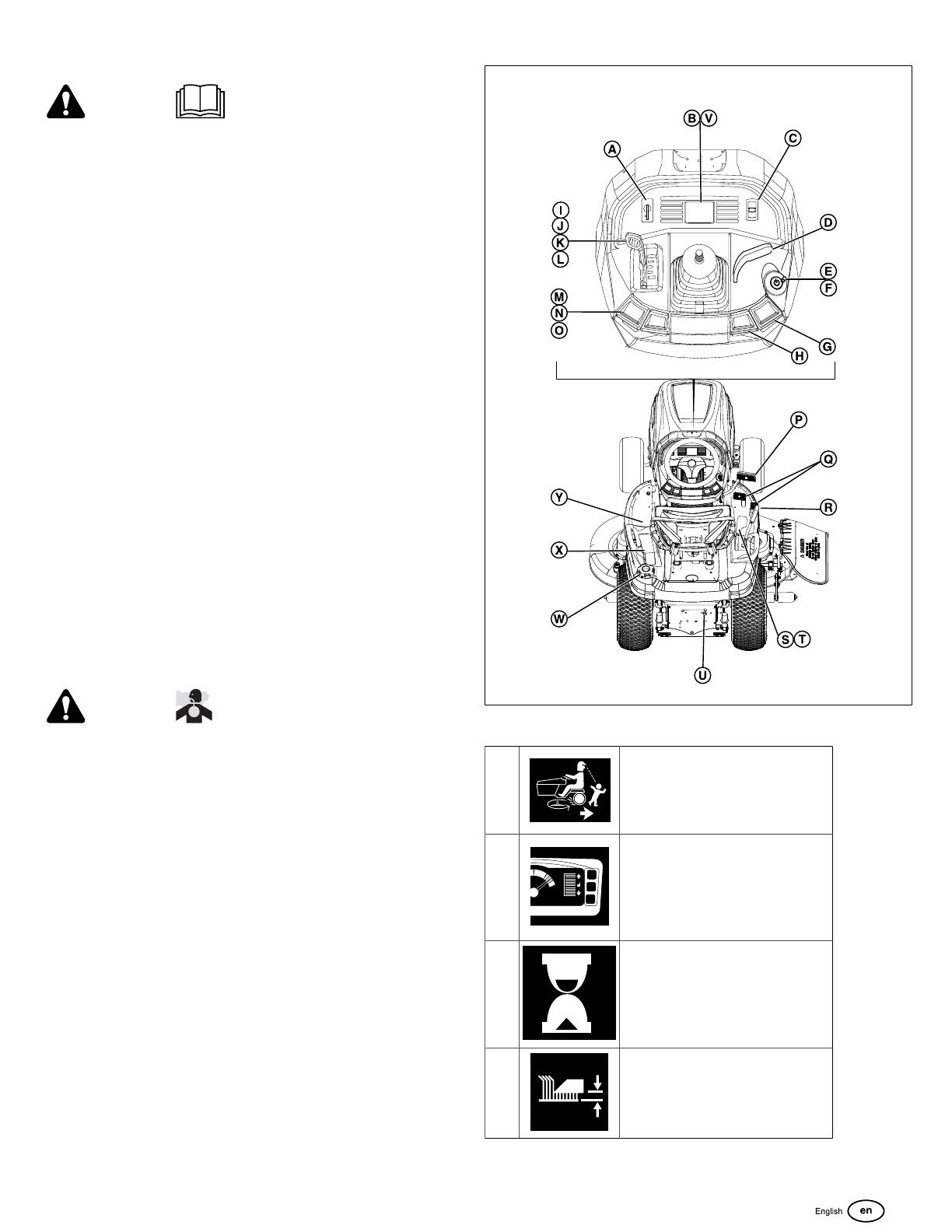
1. Engage the parking brake control (H, Figure3).
2. Make sure the PTO switch (M)is disengaged.
3. Start the engine. SeeStart Engine.
4. Set the throttle control (J)to the FAST position.
5. Engage the PTO (N) to activate the mower blades.
6. Use the Height-of-Cut Electric Switch (C)to set the
cutting height to the desired level. SeeAdjusting the
Mower Cutting Height.
7. Disengage the parking brake (H), then begin to mow.
8. Turn off the PTO.
9. STOP the engine. SeeStop Tractor and Engine.
WARNING
The engine will shut off if the reverse ground speed pedal
is depressed while the PTO is on and the RMO has not
been activated. The operator must always turn the PTO off
prior to driving across on roads, paths, or areas that can be
used by other vehicles. Sudden loss of drive could create a
hazard.
Adjust Mower Cutting Height
The mower lift lever (D and R, Figure3) lowers the deck
to the cutting position or raises the deck to the transport
position.
Lower the Deck
Mechanical Lift - (if equipped)
1. On the right side, pull back the mower lift lever (R,
Figure3) a small distance.
2. Push it to the right.
3. Move it down.
Power Lift - (if equipped)
1. Start the unit. Make sure that the brake pedal (P,
Figure3) is not pushed down.
2. Push the power lift lever (D, Figure3) forward to lower the
deck to cutting position.
Raise the Mower Deck
Mechanical Lift - (if equipped)
1. On the right side, pull up on the mower lift lever (R,
Figure3).
2. Lock in notch to the left.
Power Lift - (if equipped)
1. Start the unit. Make sure that the brake pedal
(P,Figure3) is not pushed down.
2. Pull the power lift lever (D, Figure3) back until the deck is
at its highest position. This is transport mode.
Note:Do not cut when raised in transport position.
Not for
Reproduction
13
The cutting height electric switch (C, Figure3)controls the
mower cutting height. SeeSpecificationssection for height-of-
cut specification.
Reverse Mowing Option (RMO)
DANGER
Mowing in reverse can be hazardous to bystanders.
Tragic accidents can occur if the operator is not alert to
the presence of children. Children are often attracted to
the machine and the mowing activity. Never assume that
children will remain where you last saw them.
Keep children out of the operating area and under the
watchful care of a responsible adult.
Do not carry passengers, especially children, even
with the blade(s) shut off. Children can fall off and be
seriously injured or interfere with the safe machine
operation. Children who have been given rides in
the past can suddenly appear in the mowing area for
another ride and be run over or backed over by the
machine.
Do not mow in reverse unless absolutely necessary.
Always look down and behind before and while you
mow in reverse.
If the machine mows in reverse without the Reverse
Mowing Option activated, see a Briggs & Stratton
Authorized Service dealer immediately.
Reverse Mowing
The Reverse Mowing Option (RMO) lets the operator mow in
reverse.
1. Engage the Power Take-Off (PTO) (O, Figure8).
8
2. Turn the RMO key (A) to the ON position.
3. The L.E.D. light will come on.
Note:The RMO deactivates each time the PTO is
disengaged.Remove the key to prevent access to the RMO.
Maintenance
WARNING
Unintentional sparking can result in fire or electric shock.
Unintentional start-up can result in entanglement, traumatic
amputation, or laceration.
Before performing adjustments or repairs:
Disconnect the spark plug wire and keep it away from
the spark plug.
Disconnect battery at negative terminal (only engines
with electric start).
Use only correct tools.
Do not tamper with governor spring, links, or other parts
to increase engine speed.
Replacement parts must be of the same design and
installed in the same position as the original parts.
Other parts may not perform as well, may damage the
unit, and may result in injury.
Do not strike the flywheel with a hammer or hard object
because the flywheel may shatter during operation.
Maintenance Schedule
RIDER AND MOWER
Every 8 Hours or Daily
Check the Safety interlock system
Not for
Reproduction
14
RIDER AND MOWER
Remove unwanted material from the rider, mower deck, and engine
compartment
Every 25 Hours or Annually
*
Check the tire pressure
Check the mower blade stopping time
Check for loose hardware on the rider and mower
Every 50 Hours or Annually
*
Clean the battery and cables
Check the rider brakes
Seea Briggs & Stratton Authorized Service Dealer Annually
Lubricate the rider and mower.
Mower blades check**
*Whichever comes first.
**Check the mower blades more often in regions with sandy soils or
high dust conditions.
ENGINE
First 5 Hours
Change the engine oil
Every 8 Hours or Daily
Check the engine oil level
Every 25 Hours or Annually
*
Clean the air filter and pre-cleaner**
Every 50 Hours orAnnually
*
Change the engine oil
Replace the oil filter
Annually
Replace the air filter
Replace the pre-cleaner
See Dealer Annually to
Inspect the muffler and spark arrester
Replace the spark plugs
Replace the fuel filter
Clean the air cooling system
*Whichever comes first.
**Clean more often in dusty conditions or when airborne material is
present.
Electronic Fuel Management System
The Electronic Fuel Management System monitors engine
temperature, engine speed, and battery voltage to adjust
the choke during engine starting and warm up. There are no
adjustments on the system. If starting or operation problems
occur, contact an Authorized Briggs & Stratton Dealer.
NOTICE Make sure to follow the steps below or the
Electronic Fuel Management System could be damaged.
Never start the engine if the battery cables are loose.
Turn the key to the OFF position or remove the starter
switch before disconnecting, removing and / or installing
the battery.
Never use a battery charger to start the engine.
Never disconnect the battery cables while the engine is
running.
When connecting the battery cables, first connect the
positive (+) cable and then connect the negative (-) cable
to the battery.
When charging the battery, turn the ignition switch to the
off position and disconnect the negative (-) battery cable
from the battery.
Do not spray water directly on the Electronic Control
Unit.
Charge the Battery
WARNING
Keep open flames and sparks away from the battery; the
gasses coming from it are highly explosive. Ventilate the
battery well during charging.
A dead battery or one too weak to start the engine can be the
result of a defect in the charging system or other electrical
component. If there is any doubt about the cause of the
problem, see your dealer. If you need to replace the battery,
follow the steps underClean the Battery and Cables.
To charge the battery, follow the instructions provided by the
battery charger manufacturer as well as all warnings included
in the safety rules sections of this book. Charge the battery
until fully charged. Do not charge at a rate higher than 10
amps.
Battery Maintenance
WARNING
When you disconnect the battery cables,firstdisconnect
the negative (-) battery cable and then disconnect the
positive (+) battery cable.When you connect the battery
cables,firstconnect the positive (+) battery cable and then
connect the negative (-) battery cable. If not done in this
order, the positive terminal can be shorted to the frame by a
tool.
9
1. DO NOT remove or connect a battery cable while the
engine is ON. Turn OFF the unit and remove the starter
insert.
Not for
Reproduction
15
2. First disconnect the negative (-) battery cable (A,
Figure9) from the battery. Then, disconnect the positive
(+) battery cable from the battery.
3. Remove the battery hold-down strap (B) and the battery.
4. Clean the battery compartment with a solution of baking
soda and water.
5. Clean the battery terminals and cable ends with a wire
brush and battery terminal cleaner.
6. Install the battery with the battery hold-down strap (B).
7. First connect the positive (+) battery cable to the battery.
Then, connect the negative (-) battery cable (A, Figure9)
to the battery.
8. Apply a layer of petroleum jelly or non-conducting grease
to the cable ends and the battery terminals.
Mower Blade Stop Time
WARNING
If the mower blade does not come to a complete stop within
5 seconds, the clutch must be adjusted. Do not operate the
machine until the correct adjustment has been performed by
aBriggs & Stratton Authorized Service Dealer.
The mower blades and mower drive belt must stop within
five seconds after the electric Power Take-Off (PTO) switch
turns OFF. If the mower drive belt does not stop within five
seconds, see a Briggs & Stratton Authorized Service Dealer
for repairs.
Change the Engine Oil
1. Run the engine until warm.
2. Put the tractor on a level surface (Figure,10).
10
3. Stop the engine and remove starter insert (A,Figure1).
4. Clean the oil fill and filter areas of any debris.
5. Remove dipstick (B)and lay on clean cloth.
6. Disconnect the oil drain hose (A,Figure11).
Not for
Reproduction
16
11
7. Carefully remove the cap (B)and lower hose into an
approved container (C).
8. After the oil has drained, install the cap tightly, then attach
the hose to the side of the engine.
9. Remove the oil filter (B,Figure12) and discard.
12
10. Lightly lubricate the oil filter gasket (A)with clean oil.
11. Install the oil filter by hand until the gasket touches the oil
filter adapter (C)then tighten the oil filter 1/2 to 3/4 turns.
12. Add oil. See theCheck and Add Engine Oilsection.
Service Air Filter
Refer to the Engine Manual.
Air Filter Assembly (Cartridge with pre-cleaner)
WARNING
DO NOT start or run the engine with the air cleaner
assembly or air filter removed as it is a fire hazard.

NOTICE
Do not use pressurized air or solvents to clean the filter.
Pressurized air can damage the filter, and solvents will
dissolve the filter.
1. Loosen the fasteners (A,Figure13) and remove the
cover (B).
Not for
Reproduction
17
13
2. Remove the air cleaner assembly (C)and disassemble.
3. Remove debris that might get into the carburetor throat
(D).
4. Remove the pre-cleaner from the air filter.
5. To loosen debris, gently tap the air filter on a hard
surface. If the air filter is dirty, replace it with a new air
filter.
6. Wash the pre-cleaner in liquid detergent and water. Then
let it thoroughly air dry. Do not lubricate the pre-cleaner.
7. Assemble the dry pre-cleaner to the air filter.
8. Install the air filter assembly.
9. Install the cover and secure with fasteners.
Air Filter Assembly (Cyclonic with pre-cleaner)
WARNING
DO NOT start or run the engine with the air cleaner
assembly or air filter removed as it is a fire hazard.

NOTICE
Do not use pressurized air or solvents to clean the filter.
Pressurized air can damage the filter and solvents will
dissolve the filter.
1. Loosen the fasteners (A, Figure14) and remove the
cover (B).
14
2. Open the latch (C)and remove the air filter assembly
(D).
3. Remove the pre-cleaner(E) from the air filter.
4. To loosen debris, gently tap the air filter on a hard
surface. If the air filter is dirty, replace it with a new air
filter.
5. Wash the pre-cleaner in liquid detergent and water. Then
let it thoroughly air dry. Do not lubricate the pre-cleaner.
6. Assembly the dry pre-cleaner to the air filter.
7. Install the air filter assembly and close the latch.
8. Install the cover with the fasteners.
Tire Pressure Check
For correct traction and best mowing performance, make sure
that the tire inflation pressure is 12-14 psi (0,82-0,96 bar).
Refer to Tire Pressure Check in theMaintenance Schedule.
Also, see Tire Inflation Pressure in theSpecificationssection.
Note:The Tire Inflation Pressure can be slightly different from
the "Maximum Inflation" shown on the side of the tires.
Check the Spark Plugs
WARNING
Unintentional sparking can result in fire or electric shock.
Unintentional start-up can result in entanglement, traumatic
amputation, or laceration.
When testing for spark:
Use approved spark plug tester.
Do not check for spark with spark plug removed.
Not for
Reproduction
18
NOTICE
Spark plugs have different heat ranges. It is important that
the correct spark plug is used, otherwise, engine damage
can occur. Replace the spark plug with the same type or
equivalent one.
Clean Spark Plug
Clean the spark plug with a wire brush and sturdy knife. Do
NOT use abrasives.
Check Spark Plug Gap
Use a spark plug feeler gauge (A,Figure15) to check the
gap between the two electrodes. When the gap is correct, the
gauge will drag slightly as you pull it through the gap.
To adjust the spark plug gap, use a spark plug gauge and
gently bend the curved electrode. Make sure that you do not
touch the center electrode or the porcelain. 
15
Install Spark Plug
Tighten the spark plug with your fingers, and then, tighten it
with a wrench as shown in Figure16.
180 in-lbs (20 Nm), OR
1/2 turn when you install the original spark plug. 1/4 turn
when you install a new spark plug.
16
Push the Tractor by Hand
1. Disengage the Power Take-Off (PTO) (A,Figure17).
17
2. Turn the engine OFF (B).
3. Pull the transmission release (C)to lock into released
position.
4. The rider can be pushed by hand (D).
WARNING
If you tow the unit, it will cause transmission damage. DO
NOT use another vehicle to push or pull this machine. DO
NOT push the transmission release lever while engine is
ON.
Towed Equipment
1. Before you tow the unit, make sure that the hitch is
designed for towing.
2. Attach towed equipment ONLY at the hitch point.
3. For towed equipment and towing on slopes, follow the
weight limit recommendationslisted below.
Gross weight (trailer and load) of 400 lb (181.4 kg).
Maximum of 20 lb (9.1 kg) foot up or down on the
tongue.
Not for
Reproduction
19
Go from a 10° limit to a 5°limit on any slope.
4. DO NOT let children or others in or on towed equipment.
5. The weight of the towed equipment on slopes can cause
loss of traction and loss of control.
6. DO NOT shift to neutral and coast down hill.
Clean the Mower Deck (if equipped)
Note:
Use the washout port (C,Figure18) to clean the underside of
the mower deck.
1. Put the rider on a smooth level surface.
2. Attach the quick disconnect (A,Figure18) to the garden
hose (B)and then connect to the washout port (C)on the
mower deck.
3. Turn the water ON.
4. Start the engine.
5. Set the Height-of-Cut in the highest position.
6. Engage the Power Take-Off (PTO) switch to activate the
mower blades. The rotation of the blades and the running
water will clean the underside of the mower deck.
7. Disconnect the Power Take-Off and stop the engine.
8. Turn the water OFF.
9. Remove the garden hose and quick disconnect from the
washout port (C).
18
Storage
WARNING
Never store the unit (with fuel) in an enclosed, non-
ventilated structure. Fuel vapors can travel to an ignition
source (such as a furnace, water heater, etc.) and cause an
explosion.
Store away from furnaces, stoves, water heaters, or
other appliances that have pilot lights or other ignition
sources because they can ignite fuel vapors.
Equipment
Turn OFF the Power Take-Off (PTO), and set the parking
brake. Remove the starter insert.Let the machine cool.
If you remove the battery, the battery life will increase. Make
sure that thebattery is in a cool, and dry location, and keep
it fully charged. If the battery is left in the unit, disconnect the
negative cable.
Fuel System
Fuel can become stale when kept in a storage container for
more than 30 days. Each time you fill the container with fuel,
addSTA-BIL 360°
®
PROTECTION™to the fuel as specified
by the manufacturer’s instructions. This keeps fuel fresh and
decreases fuel-related problems or contamination in the fuel
system.
It is not necessary to drain fuel from the engine whenSTA-
BIL 360°
®
PROTECTION™is added as instructed. Before
storage, turn the engine ON for 2 minutes to move the fuel
and stabilizer through the fuel system.
Before starting the machine after it has been stored:
Check all fluid levels. Check all maintenance items.
Do all recommended checks and procedures found in this
manual.
Make sure the engine is warm before you use it.
Not for
Reproduction
20
Troubleshooting
Troubleshooting the Rider
PROBLEM LOOK FOR REMEDY
The brake pedal is not pushed down. Fully push down on the brake pedal.
Empty fuel tank. If engine is hot, let the engine cool, then fill the fuel
tank.
The PTO switch is set to the ON position. Set the PTO switch to the OFF position.
The cruise control is engaged. Move the cruise control knob to the NEUTRAL/OFF
position.
The engine is flooded. Disconnect the choke.
The battery terminals require cleaning. Refer toClean the Battery and Cables.
The battery is discharged oris dead. Charge or replace thebattery.
The engine will not turnover or start.
Loose or broken wiring. Visually inspect the wiring. If wires are frayed or
broken, see an Authorized Service Dealer.
Engine starts hard or operates poorly. The fuel mixture is too rich. Clean the air filter.
Low oil level. Inspect and add oil as required.Engine knocks.
Incorrect grade of oil. Refer to theStart and Stop Enginesection.
Incorrect grade of oil. Refer to theStart and Stop Enginesection.Excessive oil consumption.
There is too muchoil in crankcase. Drain remaining oil.
The air filter is dirty. Refer to theService the Air Filtersection.Engine exhaust is black.
The choke is closed. Open the choke.
The speed control pedals are not pushed down. Push down on the speed control pedals.
The transmission release lever is in PUSH
position.
Move the transmission release lever into DRIVE
position.
Engine runs, but rider will not drive.
The parking brake is engaged. Release the parking brake.
Rider steers hard or handles poorly. Incorrect tire inflation. Refer to theCheck Tire Pressuresection.
Note:For all other problems, contact an Authorized Service Dealer.
Troubleshooting the Mower
PROBLEM LOOK FOR REMEDY
The mower cut is uneven. The rider tires are incorrectly inflated. Refer to theCheck Tire Pressuresection.
The engine speed is set too slow. Set to FAST throttle.The mowercut looks rough.
The ground speed is set too fast. Slow down.
The engine speed is set too slow. Set to FAST throttle.
The ground speed is set too fast. Slow down.
The air cleaner is clogged or dirty. Refer to theService Air Filtersection.
The Height-of-Cut set too low. Cut tall grass at maximum Height-of-Cut during first
pass.
The engine is not up to operating temperature. Operate the engine for several minutes to warm
up.
The engine stalls easily with the mower engaged.
The grass is too tall. Start the mower in a cleared area.
The engine turns ON, and the rider drives, but the
mower will not cut.
PTO not engaged. Engage PTO.
Note:For all other problems, contact an Authorized Service Dealer.
Not for
Reproduction
  • Page 1 1
  • Page 2 2
  • Page 3 3
  • Page 4 4
  • Page 5 5
  • Page 6 6
  • Page 7 7
  • Page 8 8
  • Page 9 9
  • Page 10 10
  • Page 11 11
  • Page 12 12
  • Page 13 13
  • Page 14 14
  • Page 15 15
  • Page 16 16
  • Page 17 17
  • Page 18 18
  • Page 19 19
  • Page 20 20
  • Page 21 21
  • Page 22 22
  • Page 23 23
  • Page 24 24
  • Page 25 25
  • Page 26 26
  • Page 27 27
  • Page 28 28
  • Page 29 29
  • Page 30 30
  • Page 31 31
  • Page 32 32
  • Page 33 33
  • Page 34 34
  • Page 35 35
  • Page 36 36
  • Page 37 37
  • Page 38 38
  • Page 39 39
  • Page 40 40
  • Page 41 41
  • Page 42 42
  • Page 43 43
  • Page 44 44
  • Page 45 45
  • Page 46 46
  • Page 47 47
  • Page 48 48
  • Page 49 49
  • Page 50 50
  • Page 51 51
  • Page 52 52
  • Page 53 53
  • Page 54 54
  • Page 55 55
  • Page 56 56
  • Page 57 57
  • Page 58 58
  • Page 59 59
  • Page 60 60
  • Page 61 61
  • Page 62 62
  • Page 63 63
  • Page 64 64
  • Page 65 65
  • Page 66 66
  • Page 67 67
  • Page 68 68

Briggs & Stratton 2691670 User manual

Category
Lawnmowers
Type
User manual

Ask a question and I''ll find the answer in the document

Finding information in a document is now easier with AI