Simplicity OPERATOR'S INSTRUCTION MANUAL RIDE VICTA VRX User manual

Category
Lawnmowers
Type
User manual

This manual is also suitable for

Not for
Reproduction
SIDE DISCHARGE MODELS
REAR CATCH MODELS
IMPORTANT
READ THIS BOOK CAREFULLY BEFORE OPERATING THIS MACHINE
OPERATOR MANUAL
VRX SERIES RIDE LAWNMOWER RANGE
Not for
Reproduction
2
Dear Customer,
Thank you for having chosen one of our products.
We hope that you will get complete satisfaction
from using your new machine and that it will fully
meet all your expectations.
This manual has been written to help you become
familiar with the machine and use it safely and
efficiently. Do not forget that this manual is an
integral part of the machine, so keep it close at
hand for future reference and pass it on to the
purchaser if you sell the machine.
This new lawnmower has been designed & built in
compliance with international standards (Machinery
Directive 2006/42/CE), & is safe & reliable if used
for cutting grass following the instructions given in
this manual (proper usage). If you use the machine
in any other way or ignore the instructions for safe
use, maintenance and repair, it is considered
"incorrect usage" (
5.1). In this case, the
warranty is automatically voided & the Manufacturer
is not held responsible for damage or injury to
oneself or others.
Note that some models will progressively update in
compliance with new standard ISO 5395 & may
include additional features that will affect normal
usage.
INTRODUCTION
INTENDED USE
This machine was designed & built to cut grass.
The use of special accessories provided for by
the Manufacturer as original equipment or
which may be purchased separately, allows this
work to be done in various operating modes,
illustrated in this manual or the instructions that
accompany the single accessories.
Likewise, the intended use can be amplified to
include other functions by applying
supplementary tools (if provided for by the
Manufacturer), abiding by the restrictions &
conditions indicated in the instructions
accompanying the equipment.
IMPROPER USE
Any other usage not in keeping with the
abovementioned ones may be hazardous &
harm persons and/or damage things. Examples
of improper use may include, but are not limited
to:
transporting people, children or animals on
the machine or on a trailer;
towing or pushing loads without the use of
the specific accessory for towing;
use of the machine for riding over unstable,
slippery, icy, stony, rough, marshy ground or
puddles that do not allow the consistency of
the ground to be assessed;
use the blades on surfaces other than grass.
use of the machine for leaf or debris
collection.
Improper use of the machine will invalidate the
warranty, relieve the Manufacturer from all
liabilities, and the user will consequently be
liable for all and any damage or injury to
himself or others.
AFTER-SALES SERVICE
This manual gives all the necessary instructions
for using the machine & carrying out basic
maintenance.
Any adjustments or maintenance operations
not described in this manual must be
carried out by your Dealer or a specialized
Service Centre. Both have the necessary
knowledge and equipment to ensure that
the work is done correctly without affecting
the safety of the machine.
If you wish, you can ask your dealer to prepare
a maintenance programme personalised to
your needs. This will help you keep your new
purchase in peak performance and maintain its
value over time.
To contact your closest Victa Authorised Service Centre, you will find the latest
Service Centre listing on the Victa website, www.victa.com.au or by contact
Victa Customer Service on 1800 356 632.
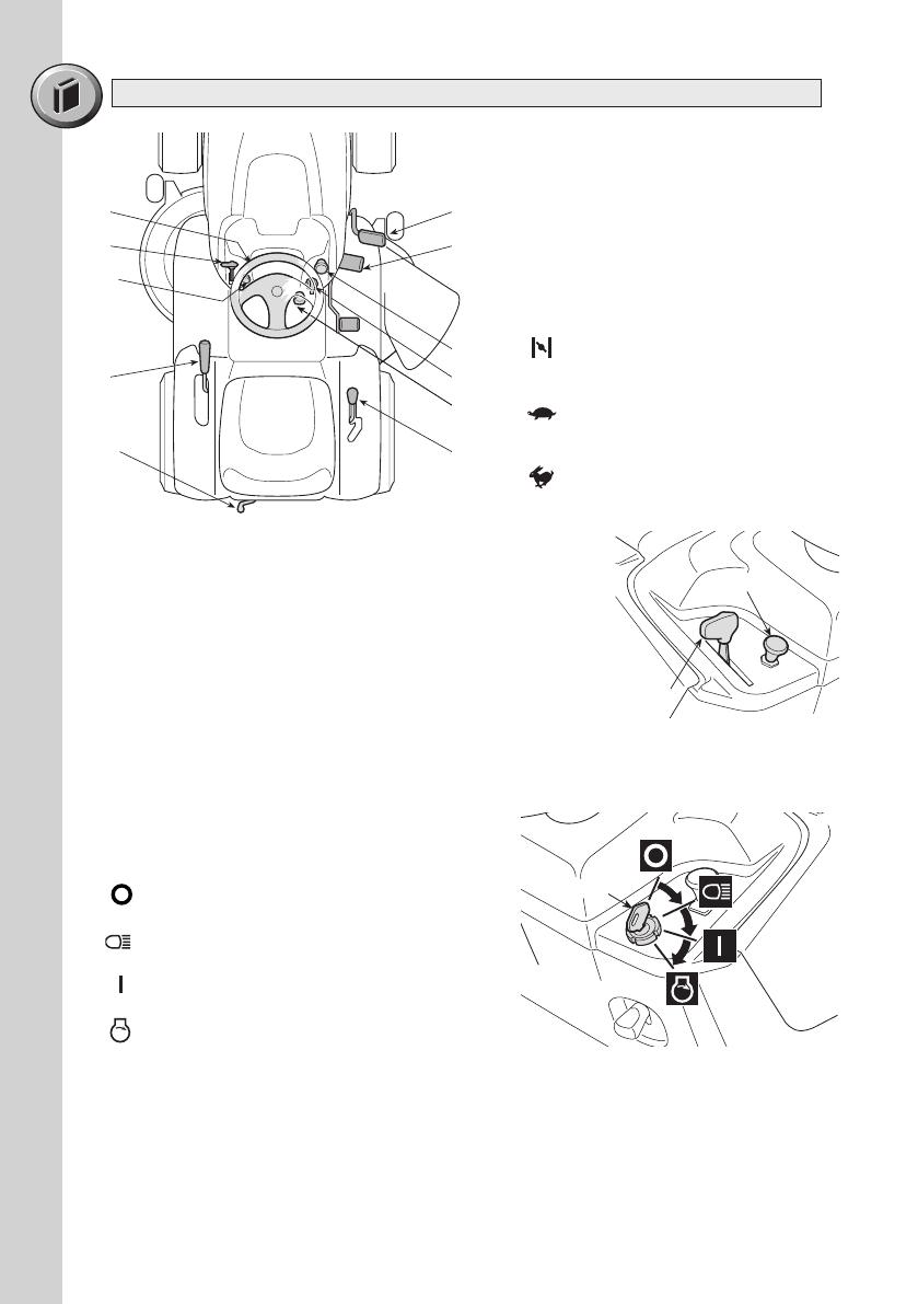
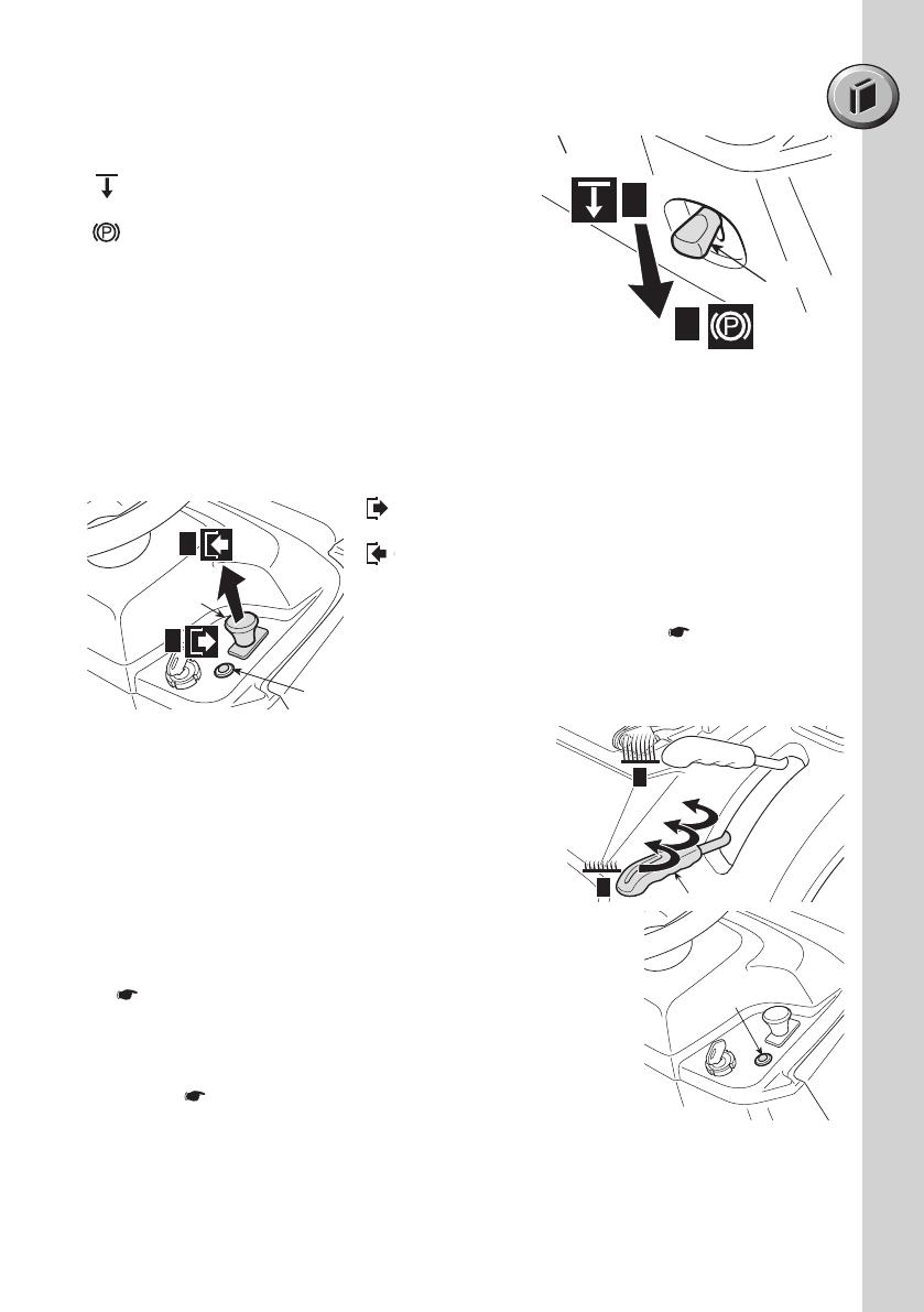
This may include limitations with regards
to reverse movement operations and can
be identified in the addition of the reverse
button (4.4) located on the dashboard of
some models.
4.4
Since we regularly improve our products, you may
find slight differences between your machine and
the descriptions contained in this manual.
Modifications can be made to the machine without
notice and without the obligation to update the
manual, although the essential safety and function
characteristics will remain unaltered. If in doubt, do
not hesitate to contact your dealer.
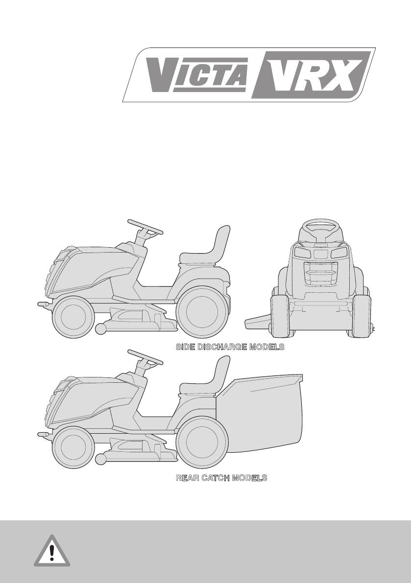
This machine is a garden tool & precisely a ride-on
mower.
The machine is equipped with an engine which
drives a cutting unit protected by a casing, as well
as a transmission unit that moves the machine.
The operator is able to operate the machine and
use the main controls, always seated in the
operator’s position.
The devices fitted on the machine stop the engine
and the cutting device within a few seconds, should
the operator behave in a manner that does not
comply with the necessary safety precautions.
Not for
Reproduction
3
1. SAFETY ....................................................................................................................
Regulations for using the machine safely
2. IDENTIFICATION OF THE MACHINE AND COMPONENTS ..................................
How to identify the machine and its main components
3. UNPACKING AND ASSEMBLY .................................................................................
How to remove the packing and assemble loose parts
4. CONTROLS AND INSTRUMENTS ............................................................................
Position and functions of all the controls
5. HOW TO USE THE MACHINE ..................................................................................
Instructions for working efficiently and safely
5.1 Safety recommendations ......................................................................................
5.2 Why the safety devices cut in ..............................................................................
5.3 Preliminary operations before starting work ........................................................
5.4 Using the machine ...............................................................................................
5.5 Using on slopes ...................................................................................................
5.6 Transporting the machine .....................................................................................
5.7 Lawn maintenance ................................................................................................
6. MAINTENANCE .........................................................................................................
All the information for maintaining the machine in peak efficiency
6.1 Safety recommendations ......................................................................................
6.2 Routine maintenance ............................................................................................
6.3 Interventions on the machine ...............................................................................
7. ENVIRONMENTAL PROTECTION ............................................................................
Advice on machine use and respecting the environment
8. TROUBLESHOOTING ...............................................................................................
A help in quickly solving problems
9. ACCESSORIES ON REQUEST ................................................................................
A description of the accessories available for special requirements
10. SPECIFICATIONS ......................................................................................................
A summary of the main specifications of your machine
TABLE OF CONTENTS
1
5
6
13
16
16
17
17
21
25
26
26
27
27
28
32
34
35
37
38
WARRANTY - NOTE PRODUCT WARRANTY DETAILS ARE NOT WRITTEN WITHIN
IN THIS OPERATORS MANUAL. REFER TO OTHER DOCUMENTS SUPPLIED WITH
MACHINE FOR PRODUCT WARRANTY DETAILS.
Not for
Reproduction
1
1.1 HOW TO READ THE MANUAL
Some paragraphs in the manual containing important information regarding safety and
operation are emphasized in the following ways:
NOTE
or
IMPORTANT
These give details or further information
on what has already been said, in the aim to prevent damage to the machine.
WARNING!
Non-observance will result in the risk of injury to oneself
or others.
DANGER!
Non-observance will result in the risk of serious injury or death to
oneself or others
This manual describes various versions of the machine, which mainly differ as follows:
type of transmission: with either mechanical gear change or hydrostatic continuous
speed adjustment. The models with hydrostatic transmission are identified by the word
"HYDRO" on the identification label (
2.1);
the inclusion of components or accessories which are not widely available;
special equipment fitted.
The symbol “
highlights all the differences in usage and is followed by the
indication of the version to which it refers.
The symbol
refers to another part of the manual where further information can be
found.
1. SAFETY
NOTE
Positions on the ma chine, such as “front”, “back”, “left” or “right”
hand side, refer to the direction of forward travel.
IMPORTANT
For all operations regarding the use and
maintenance of the engine or the battery not described in this
manual, refer to the relevant manuals which form an integral
part of all the documentation supplied with the machine.
1.2 GENERAL SAFETY REGULATIONS
WARNING!
Read carefully before using the machine.
A) TRAINING
1) Read the instructions carefully. Be familiar with the controls
and how to use the equipment properly.
2) Never let children or people unfamiliar with these instructions use the machine.
Local regulations can restrict the age of the user.
3) Never mow while people, especially children, or pets are nearby.
Not for
Reproduction
2
4) Keep in mind that the operator or user is responsible for accidents or hazards
oc curring to other people or their pro perty.
5) Do not carry passengers.
6) All drivers should seek and obtain professional and practical instruction. Such
instruction should emphasise:
the need for care and concentration when working with ride-on machines;
you cannot use the brake to regain control of a ride-on machine sliding down a
slope. The main reasons for loss of control are:
insufficient wheel grip;
overspeeding;
inadequate braking;
the type of machine is unsuitable for its task;
unawareness of the effect of ground conditions, especially slopes;
incorrect hitching and load distribution.
B) PREPARATION
1) While mowing, always wear sturdy footwear and long trousers. Do not operate
the equipment barefoot or wearing open sandals.
2) Thoroughly inspect the area where the equipment is to be used and remove all
objects which can be ejected from the machine.
3) DANGER! Petrol is highly flammable:
store fuel in containers specifically designed for this purpose;
refuel outdoors only and do not smoke while refuelling;
add fuel before starting the engine. Never remove the cap of the fuel tank or
add petrol while the engine is running or when the engine is hot;
if you spill petrol, do not start the engine and move the machine away from the area
of spillage. Do not create any source of ignition until the petrol vapours have evapo-
rated;
put back and tighten all fuel tank and container caps securely.
4) Replace faulty silencers.
5) Before use, always inspect the machine to check that the blades, blade bolts and
cutter assembly are not worn or damaged. Replace worn or damaged blades and bolts
in sets to preserve balance.
6) On multi-bladed machines, remember that the rotation of one blade can cause
other blades to rotate.
C) OPERATION
1) Do not start the engine in a confined space where dangerous carbon monoxide
fumes can collect.
2) Mow only in daylight or good artificial light.
3) Before starting the engine, disengage the blades and shift into neutral.
4) Do not use on slopes of more than 10 Degrees.
5) Remember there is no such thing as a “safe” slope. Travelling on grass slopes
requires particular care. To guard against overturning:
do not stop or start suddenly when going up or downhill;
engage the drive slowly and always keep the machine in gear, especially when
travelling downhill;
machine speeds should be kept low on slopes and during tight turns;
stay alert for humps and hollows and other hidden hazards;
never mow across the face of the slope.
Not for
Reproduction
3
6) Use care when pulling loads or using heavy equipment:
use only approved drawbar hitch points;
limit loads to those you can safely control;
do not turn sharply. Use care when reversing;
7) Disengage the blades before crossing surfaces other than grass.
8) Never use the machine with damaged guards, or without the safety
protective devices in place.
9) Do not change the engine governor settings or overspeed the engine as it
may void engine & product warranty. Operating the engine at excessive speed can
increase the risk of personal injury and may void warranty.
10) Before leaving the driving seat:
disengage the blades and lower the attachments;
go into neutral and apply the parking brake;
stop the engine and remove the ignition key.
11) Disengage the blades, stop the engine and remove the ignition key:
before clearing blockages or unclogging the discharge chute (side eject models) or
the rear bag grass collector chute;
before cleaning, checking or servicing the machine;
after striking a foreign object. Inspect the machine for damage and make repairs
before restarting and operating the machine;
If the machine starts to vibrate abnormally (check for the causes immediately).
12) Disengage the blades for transport or whenever they are not in use.
13) Stop the engine and disengage the blades:
before refuelling;
before removing the grass catcher (rear bag collect models)
14) Reduce the throttle during engine r un-out. If the engine is provided with a shut-off
valve, cut off the fuel when you have finished mowing.
D) MAINTENANCE AND STORAGE
1) Keep all nuts, bolts and screws tight to be sure the equipment is in safe working
condition.
2) Never store the equipment with petrol in the tank inside a building where fumes
may reach an open flame or spark.
3) Allow the engine to cool before storing in any enclosure.
4) To reduce fire hazards, keep the engine, silencer, battery compartment and petrol
storage area free of grass, leaves, or excessive grease.
5) Replace worn or damaged parts for safety purposes. Check the grass catcher
frequently for wear or deterioration (rear bag collect models). The catcher fabric is a
high wear item and may need to be replaced when worn. Always clean and empty
catcher before storing.
6) If the fuel tank has to be drained, this should be done outdoors.
7) On multi-bladed machines, remember that the rotation of one blade can cause
other blades to rotate.
8) When the machine is to be stored or left unattended, lower the cutting deck.
1. SAFETY (cont.)
Not for
Reproduction
4
1.4 REGULATIONS FOR TOWING
A kit for towing a small trailer is supplied on some models.
This accessory is to be fitted following the instructions
provided.
When using the towing kit, do not exceed the
recommended loads stated on the label & follow the safety
instructions (
1.2, C-6).
1
Warning: Read the instructions before operating this machine.
2A
Danger! Ejected objects: Do not operate without the stone-guard in place.
(Side discharge models only)
Danger! Ejected objects: Do not operate without either the rear discharge guard or the
grass-catcher being in place. (Rear catch models only)
3
Danger! Ejected objects: Keep bystanders away.
4
Warning: Disconnect the ignition key and read the instructions before carrying out any
repair or maintenance work.
5
Danger! Machine rollover: Do not use this machine on slopes steeper then 10°.
6
Danger! Dismemberment: Make sure that children stay clear of the machine at all time
when engine is running.
Danger of cutting yourself. Blades in movement.
Do not put hands or feet near or under the opening of the cutting plate.
Warning! - Keep away from hot surfaces.
max 245 N (25 kg)
max 980 N (100 kg)
1.3 SAFETY LABELS
Your machine must be used with care. This is why labels with illustrations have
been placed on the machine, to remind you of the main precautions to take during
use.
These labels are to be considered an integral part of the machine.
Should a label come off or become illegible, contact your dealer to replace it.
Their meaning is explained below.
1
2A 3
4 5 6
1 2A 3
4 5
6
1 2A 3
4
5
6
1 2A 3
4
5 6
1 2A
3
4 5 6
7
7
8
2B
2B
7
8
1
2A
3
4 5 6
Not for
Reproduction
5
1
8
2
3
4
5
6
7
2.1 IDENTIFICATION OF THE MACHINE
The label located near the battery housing
has the essential data of each machine.
** Rear catch bag illustrated
(only available on selected models.)
1. Brand Marking
2. Model Number
3. Barcode Number
4. Date of Manufacture
5. Serial Number
6. Article Number
7. Noise Rating according to
Manufacturer test standard
2. IDENTIFICATION OF THE MACHINE & COMPONENTS
Write your machine’s serial number here (5)
2.2 IDENTIFICATION OF MAIN COMPONENTS
The main components of the machine have the following functions:
11. Cutting deck: this is the guard housing
the rotating blades.
12. Blades: these are what cut the grass.
The wings at the ends help convey the
cut grass towards the collector channel.
13A. Stone-guard or deflector: It is a
safety guard which prevents objects
drawn up by the blades from being
thrown outside of the machine.
(Side discharge models only)
13B. Collector channel: this is the part connecting the cutting deck to the grass-
catcher. (Rear catch models only)
13C. Grass-catcher: as well as collecting the grass cuttings, this is also a safety
element that stops any objects drawn up by the blades from being thrown
outside of the machine. (Rear catch models only)
14. Engine: this moves the blades and drives the wheels. Its specifications and
regulations for use are described in a specific manual.
15. Battery: provides the energy for starting the engine.
16. Driving seat: this is where the machine operator sits. It has a sensor
connected to safety devices for detecting the presence of the operator.
17. Regulation and safety labels: give reminders on the main regaulations for
working safely, each of which is explained in chapter 1.
18. Front Bumper: This is a safety guard and must be fitted to all machines.
16
13C**
17 14
13A**
11
15
12
18
13B**
**
** ITEMS ONLY ON SELECT MODELS
Not for
Reproduction
3. UNPACKING AND ASSEMBLY
6
For storage and transport purposes, some components of the machine are not
installed in the factory and have to be assembled after unpacking. Follow the
instructions below.
IMPORTANT
The machine is supplied without engine oil or fuel. Before
starting the engine, fill with oil and fuel following the instructions given in the
engine manual.
WARNING!
Unpacking and completing the assembly should be
done on a flat and stable surface, with enough space for machine handling
and its packaging, always making use of suitable equipment.
3.1 UNPACKING
When unpacking the machine, take care to gather all individual parts and fittings,
and do not damage the cutting deck when taking the machine off the pallet.
The packaging contains:
the machine;
the steering wheel;
the dashboard cover;
the seat;
the battery;
– the front bumper
( 2.2, #18) If not preassembled in factory,
Check front of machine. Must be fitted.
the stone-guard;
(Side discharge models only)
– the grass catcher (with instructions) (Rear catch models only)
– the lower part of the rear plate, the grass catcher brackets and accessories
necessary for completing and assembly (Rear catch models only)
NOTE
Only some model are supplied inclusive of some kits
such as the Mulching Plug, Tow Hitch and Battery Charger. These kits will
require assembly according to the instructions and are not factory fitted.
NOTE
To prevent damage to the cutting deck, raise it to its
maximum height and take upmost care when taking the machine off the pallet.
Hydrostatic transmission
To make it easier to get the machine off
the pallet and to move it, the drive disengage lever should be put in position
«B» (
4.33).
Disposal of the packaging should be done in
accordance with the local regulations in force.
3.2 FITTING THE STEERING WHEEL
Put the machine on a flat surface & straighten up
the front wheels.
Mount the hub (1) on the shaft (2), making sure
that the plug (3) is correctly fitted into the hub seat.
Fit the dashboard cover (4) clicking the seven
fasteners into place.
1
2
3
4
an envelope containing:
the operator’s manuals & documents,
steering wheel assembly parts & seat
assembly bolts & screws
stone-guard fasteners
(Side discharge models only)
the connection screws for the battery
cables
2 starter keys,
1 spare 10 A fuse.
Not for
Reproduction
7
First connect the red wire (3)
to the positive pole (+) and
then the black wire (4) to the
negative pole (–), using the
screws supplied as shown.
Apply silicone grease to the
terminals and check that the
protective cap for the red wire
(8) is in place.
IMPORTANT
Always fully charge the battery according to the instructions
in the battery’s manual (
6.2.3).
IMPORTANT
To prevent the safety device in the electronic circuit board
from cutting in, never start the engine until the battery is fully charged!
WARNING!
Do not use the machine without the spring (2) or with the
battery incorrectly fixed in its housing.
2
3
3
1
5
1
6
7
8
1
2
3
4
5
3. UNPACKING AND ASSEMBLY (cont.)
Fit the steering wheel (5) onto the
hub (1) with the spokes directed
towards the seat.
Fit the spacer (6) and fasten the
steering wheel in place using the
screws supplied (7), in the indicated
order.
Fit the steering wheel cover (8)
clicking the three fasteners into place.
3.3 FITTING THE SEAT
Mount the seat (1) on the plate (2)
using the screws (3).
3.4 ASSEMBLY & CONNECTING
THE BATTERY
The battery (1) is housed under the
seat and secured by a spring (2).
Not for
Reproduction
2b
1
3
2b
1
4
3
2
4a
5
4
5a
1
2
2a
2
2
8
3.6.1 FITTING THE SIDE DISCHARGE CHUTE - STONE GUARD
(SIDE DISCHARGE MODELS ONLY)
Inside the stone-guard (1), fit the spring (2) by inserting
the terminal (2a) into the hole and turning it so that both
the spring (2) and the terminal (2a) are securely
positoned in their seatings.
Position the stone-guard (1) in line with the cutting deck
brackets (3). Using a screwdriver, turn the second terminal
(2b) of the spring (2) to bring it outside the stoneguard.
Fit the pin (4) in the holes on the brackets (3) & on the stone-guard, so that it passes
thrugh the coils of the spring (2) & the drilled end comes out of the inner most bracket.
Fit the cotter pin (5) in the hole (4a) of the pin (4) & turn the pin until the two ends (5a)
of the split pin can be bend (using pliers), so that it cannot slip out and let the pin fall
out (4).
WARNING!
Check that the spring works correctly and keep the stone-guard securely lowered.
Make sure that the pin is fitted properly to prevent it from falling out accidently.
Do not use the machine without the Side Discharge Chute (Stone -Guard) (1)
correctly fitted. The Side Discharge Chute must be fitted at all times, regardless of
the use of a mulching plug.
3.5 FITTING THE FRONT BUMPER
Fit the Front Bumper (1) onto the chassis
mounting holes (5) and fasten in place
using screws (2) four places.
Note that access can be improved by
temporarily removing the Hood Bonned from
the Hinge (3), or by turning the steering
wheel to adjust the position of the wheel (4).
WARNING!
Do not use the
machine without the Front Bumper (1)
correctly fitted to the chassis (5)!
171505434/0
2
3
5
4
1
2b
1
3
2b
1
4
3
2
4a
5
4
5a
1
2
2a
2
2
2b
1
3
2b
1
4
3
2
4a
5
4
5a
1
2
2a
2
2
2b
1
3
2b
1
4
3
2
4a
5
4
5a
1
2
2a
2
2
2b
1
3
2b
1
4
3
2
4a
5
4
5a
1
2
2a
2
2
Not for
Reproduction
9
3. UNPACKING AND ASSEMBLY (cont.)
3.6.2 ASSEMBLY AND COMPLETING
THE REAR PLATE (Rear Catch
Models Only)
Assemble the two lower brackets (1) and
(2), following the assembly direction as
shown in the illustration, and fasten them
with the screws (3) and nuts (4), tightening
them completely.
Remove the two screws (8), which will be
used later.
Assemble the lower part (5) of the rear plate
and fasten it to the lower brackets with the
screws (6) and bolts (7), without tightening
them completely.
1
2
3
3
4
4
8
8
5
7
6
7
6
Not for
Reproduction
10
Insert the lever (11) of the grass-catcher
full” indicator into its seat (12) and push
it down until you hear a click.
Assemble the two grass-catcher
brackets (21) and (22), following
the assembly direction as shown
in the illustration, and fasten them
with the screws (23) and snap
washers (24), tightening them
rmly.
Finish fastening the lower part (5) of the
rear plate, completely tightening the two
central screws (8) that you previously
removed and the four upper screws (9);
then tighten the two lower nuts (7) com-
pletely.
5
5
8
8
9 9
99
11
12
24 23
21
24 23
22
Not for
Reproduction
11
3.7 REPOSITIONING THE
ANTI-CHIPPING WHEELS
For transport reasons, on some
select models the anti-chipping
wheels (1) are fastened on the top
hole. In order for them to work
properly, the anti-chipping wheels (1)
must be repositioned in the hole
which is most suited for the type of
ground (
5.4.5).
3.8 FITTING & USING THE MULCHING PLUG (OPTIONAL) (SIDE DISCHARGE
MODELS ONLY)
NOTE
The mulching plug
kit is not supplied as standard on all
models. The mulching plug kit is not
factory assembled. Additional brackets
or other parts may be required if
Ordering Mulch Kits for models that do
not have the Mulch Plug supplied as
standard.
WARNING!
Always fit &
dismantle the accessory with the
engine off, after removing the ignition
key and engaging the parking brake.
You always need to work with the
stone-guard fitted properly even when
using the mulching plug accessory.
To fit, lift the stone-guard & place the
mulching plug over the cutter deck
opening.
Ensure the inner rib (2) of the Mulching
Plug locates inside the opening of the
cutter deck.
Roll the mulching plug into place so that
the rib (1) inserts beneath the stone guard
hinge (3).
Insert bolt from underside of cutter deck,
through the plug and secure on topside
using pin clip.
Before use or turning on the machine,
check that the plug is secure.
1
3. UNPACKING AND ASSEMBLY (cont.)
1
2
3
4
Not for
Reproduction
12
For a sound operation, mow the lawn frequently and regularly to reduce the height
of the grass.
Always avoid removing a large
quantity of grass, to avoid
blocking the cutting deck or
overloading the engine and the
cutting parts.
Regulate the forward speed
depending on the lawn
conditions and the quantity of
grass removed. The cutting
deck mulching plug recycles
grass inside the cutting deck,
chopping it into fine strands
and strewing them evenly on
the lawn.
The grass cuttings are left on the lawn, protecting it from drying out during
heatwaves. These finely chopped grass cuttings decompose quickly, nourishing
the soil.
3.9 FITTING THE TOW HITCH
(OPTIONAL)
When using the towing kit, do not
exceed the recommended loads (
1.4) & follow the safety
instructions (
1.2, C-6 & 1.4).
NOTE
The tow hitch kit is not supplied as
standard on all models.
The tow hitch kit is not factory
assembled.
To fit, remove two mounting hole caps
(1) by knocking out with a hammer &
pin.
Insert two mounting bracket studs (2)
through each mounting hole so that the
stud protrude outwards from the rear of
the machine.
Mount the main tow hitch bracket (3)
over the two mounting bracket studs (2)
and secure in place with nuts (4).
max 245 N (25
k
g)
max 980 N (100 kg)
1
2
3
4
MULCHING
SIDE EJECT
Not for
Reproduction
13
4.1 STEERING WHEEL
Turns the front wheels.
4.2 THROTTLE
This regulates the engine's r.p.m.
The positions are indicated on a
plate showing the following sym-
bols:
«CHOKE» cold starting
«SLOW» for minimum engine
speed
«FAST» for maximum engine
speed
4. CONTROLS AND INSTRUMENTS
4.21-4.31
4.31
4.3
1
4.22
4.1
4.2
4.6
4.32
4.4
4.2a
4.5
4.2
4.2a
The «CHOKE» position enriches the mixture so must
only be used for the time necessary when starting
from cold.
When moving from one area to another, put the lever
in a position between «SLOW» and «FAST».
When cutting, shift into «FAST».
4.2a CHOKE CONTROL (if fitted)
It enriches the mixture and must only be used for the necessary time for cold
starting.
4.3 KEY IGNITION SWITCH
This key operated control has four positions:
«OFF» everything is switched off;
«HEADLIGHTS ON» (if fitted);
«ON» activates all parts;
«START» connects the starter motor.
If you release the key on «START», it will automatically return to «ON».
After turning the engine on, turn the lights on
(if fitted) by turning the key to the
«HEADLIGHTS ON» position.
to switch them off, turn the key to «ON».
4.3
Not for
Reproduction
14
4.5 BLADE ENGAGEMENT AND BRAKE CONTROL
The mushroom switch allows you to engage the blades using the electromagnetic
clutch:
«A» Pressed = Blades disengaged
«B» Pulled = Blades engaged
If you engage the blades without taking the
necessary safety precautions, the engine shuts
down and cannot be restarted (
5.2).
Blade disengagement (Pos. «A»), simultaneously
activates a brake which stops their rotation in a few
seconds.
4.4 PARKING BRAKE
This brake stops the machine from moving when it has been parked.
There are two positions:
«A» = Brake off
«B» = Brake on
The brake is applied by pressing the pedal right
down (4.21 or 4.31) and moving the lever to
position «B». When you take your foot off the
pedal it will be blocked by the lever in the
lowered position.
To disengage the parking brake, press the pedal (4.21 or 4.31). The lever will
return to position «A».
B
A
4.4
4.5
4.7
A
B
4.6 CUTTING HEIGHT ADJUSTMENT LEVER
There are seven positions for this lever (shown as
«1» to «7» on the label), which correspond to
various heights between 3 and 8 cm.
To go from one position to another, move the lever
sideways and put it back in one of the stop
notches.
4.7 LIGHT AND SOUND WARNING DEVICE (Rear catch
models only)
The sound warning indicates that the grass-catcher is full
(
5.4.6).
This light comes on when the key (4.5) is in the “ON” position
and stays on while the machine is running
.
When it flashes, this means the engine is not ready to be
started (
5.2).
4.8 LEVER FOR TIPPING THE GRASS-CATCHER (if present on Rear catch
models only)
This pull-out lever tips and empties the grass-catcher. This means less work for the
operator.
4.6
1
7
4.7
Not for
Reproduction
15
Mechanical transmission
4.21 CLUTCH / BRAKE PEDAL
This pedal has two functions: during the first part of
its travel it acts as a clutch, engaging & disengaging
drive to the wheels, and in the second part it acts as
a brake on the rear wheels.
IMPORTANT
Do not keep the pedal halfway between clutch
engagement or disengagement, as this can cause overheating and damage the
transmission belt.
NOTE
When the machine is moving, keep your foot off the pedal.
4.21
4.22 SPEED CHANGE LEVER
This lever has seven positions for the 5 forward
speeds, the neutral position «N», and reverse «R».
To go from one speed to another, press the pedal
(4.21) halfway and shift the lever as shown on the
label.
WARNING!
Only shift into reverse when
the machine has stopped moving. Always
disengage the Blades when reversing & check
behind you.
Hydrostatic transmission
4.31 BRAKE PEDAL
This pedal works the brake on the rear wheels.
4.32 DRIVE PEDAL
This pedal engages drive in the wheels &
controls the machine’s forward & reverse speeds.
To engage forward drive, press it towards «F»
with your toecap. As you increase the pressure
on the pedal, the speed of the machine
increases.
Reverse is engaged by pressing the pedal with
the heel towards «R».
The pedal automatically goes into neutral «N»
when released. speeds.
WARNING!
Only shift into reverse when the machine has stopped
moving. Always disengage the Blades when reversing & check behind you.
NOTE
If the drive pedal is used, whether forwards or for reverse,
the engine stops as soon as the parking brake (4.4) is engaged.
4.22
5
R
2
3
4
N
1
4.31
4.32
R
N
F
4. CONTROLS (cont)
Not for
Reproduction
16
4.33 HYDROSTATIC TRANSMISSION DISENGAGEMENT LEVER
This lever has two positions:
«A» = Transmission engaged: for all
uses, when moving & during cutting;
«B» = Transmission disengaged: this
makes it much easier to move the
machine by hand, with the engine
turned off.
IMPORTANT
To avoid damage to the transmission unit, this operation
must be carried out only when the engine has stopped with the pedal (4.32)
on position «N».
4.4 REVERSING
Some select models have been updated with the additional safety
features to standards that affect reversing functions. These models are
fitted with a Reverse button (4.4) on the dashboard, which must be
pressed prior to and held down whilst reversing. Failure to Press the
Reverse button whilst reversing may cutout stop the engine.
4.33
A
B
5.1 SAFETY RECOMMENDATIONS
DANGER!
The machine must only be used for the purpose for which it
was designed (cutting grass). Using the machine in any other way is considered
“improper use” which will invalidate the warranty, relieve the manufacturer from all
liabilities, and the user will consequently be liable for all and any damage or injury to
himself or others. Examples of improper use may include, but are not limited to:
transport people, children or animals on the machine or on a trailer;
tow or push loads without the use of the specified accessory for towing;
use of the machine for moving over unstable, slippery, icy, stony, rough, marshy
ground & puddles that do not allow for evaluation of the consistency of the ground;
use of the blades on surfaces other than grass.
DANGER!
Do not tamper with or remove the safety devices fitted on the
machine. REMEMBER THAT THE USER IS ALWAYS RESPONSIBLE FOR DAMAGE
AND INJURY TO OTHERS. Before using the machine:
read the general safety regulations (
1.2), paying particular attention to driving
and cutting on slopes;
carefully read the instructions for use, make sure you are familiar with the
controls and know how to stop the blades and the engine quickly;
never put your hands or feet next to or beneath the rotating parts and always
keep away from the exit.
5. HOW TO USE THE MACHINE
4.4
Not for
Reproduction
17
WARNING!
This machine must not be used on slopes steeper than 10
Degrees (
5.5).
IMPORTANT
All the references relating to the positions of controls are
described in chapter 4.
5.2 WHY THE SAFETY DEVICES CUT IN
The safety devices work in two ways:
they prevent the engine from starting if all the safety requirements have not been met;
they stop the engine if even just one of the safety requirements is lacking.
a) To start the engine, it is necessary that:
the transmission is in “neutral”;
the blades are not engaged;
the operator is seated or the parking brake is engaged.
b) The engine stops when:
the operator leaves his seat when the blades are engaged;
the operator leaves his seat when the transmission is not in “neutral”;
the operator leaves his seat with the transmission in “neutral” but without applying
the parking brake;
the parking brake is engaged without disengaging the blades.
the speed change is activated (
4.22) or the drive pedal ( 4.32) with the
parking brake on.
reversing without pressing & holding the reversing button (only fitted to some
models with a reversing button on the dashboard)
5.3 DIRECTIONS BEFORE STARTING WORK
Before starting to mow, it is necessary to carry
out several checks and operations to ensure
you can work efficiently and in maximum
safety.
5.3.1 Seat adjustment
To change the seat position, loosen the four
fixing bolts (1) and slide it along the slots.
Once you have found the right position, tighten
the four screws (1).
1
1
Do not use the machine when in a precarious state of health or under the effect
of medicine or any other substances that can reduce your reflex actions and
your ability to concentrate.
It is the user’s responsibility to assess the potential risk of the area where work is
to be carried out, and to take all the necessary precautions to ensure his own
safety and that of others, particularly on slopes or rough, slippery & unstable
ground.
Do not leave the machine on high grass with the engine running to avoid the risk
of starting a fire.
  • Page 1 1
  • Page 2 2
  • Page 3 3
  • Page 4 4
  • Page 5 5
  • Page 6 6
  • Page 7 7
  • Page 8 8
  • Page 9 9
  • Page 10 10
  • Page 11 11
  • Page 12 12
  • Page 13 13
  • Page 14 14
  • Page 15 15
  • Page 16 16
  • Page 17 17
  • Page 18 18
  • Page 19 19
  • Page 20 20
  • Page 21 21
  • Page 22 22
  • Page 23 23
  • Page 24 24
  • Page 25 25
  • Page 26 26
  • Page 27 27
  • Page 28 28
  • Page 29 29
  • Page 30 30
  • Page 31 31
  • Page 32 32
  • Page 33 33
  • Page 34 34
  • Page 35 35
  • Page 36 36
  • Page 37 37
  • Page 38 38
  • Page 39 39
  • Page 40 40
  • Page 41 41
  • Page 42 42
  • Page 43 43
  • Page 44 44

Simplicity OPERATOR'S INSTRUCTION MANUAL RIDE VICTA VRX User manual

Category
Lawnmowers
Type
User manual
This manual is also suitable for

Ask a question and I''ll find the answer in the document

Finding information in a document is now easier with AI