NordicTrack c1500 831.24992.0 User manual
- Category
- Treadmills
- Type
- User manual
This manual is also suitable for

,®
www.nordictrack.com
Model No. 831.24992.0
Serial No.
Write the serial number in the space
above for reference.
Serial Number
Decal
QUESTIONS?
If you have questions, or if parts are
damaged or missing, DO NOT CON-
TACT THE STORE; please contact
Customer Care.
IMPORTANT: Please register this
product (see the limited warranty
on the back cover of this manual)
before contacting Customer Care.
CALL TOLL-FREE:
1-800-TO-BE-FIT
(1-800-862-3348)
Mon.-Fri. 6 a.m.-6 p.m. MT
Sat. 8 a.m.-4 p.m. MT
ON THE WEB:
www.nordictrackservice.com
USER'S
A IAL

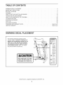
TABLE OF CONTENTS
WARNING DECAL PLACEMENT .............................................................. 2
IMPORTANT PRECAUTIONS ................................................................ 3
BEFORE YOU BEGIN ...................................................................... 5
ASSEMBLY ............................................................................... 6
HOW TO USE THE CHEST PULSE SENSOR ................................................... 13
OPERATION AND ADJUSTMENT ............................................................ 14
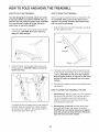
HOW TO FOLD AND MOVE THE TREADMILL .................................................. 24
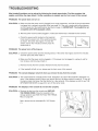
TROUBLESHOOTING ..................................................................... 25
EXERCISE GUIDELINES ................................................................... 28
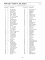
PART LIST .............................................................................. 30
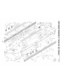
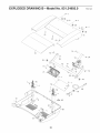
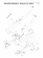
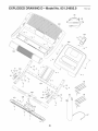
EXPLODED DRAWING .................................................................... 32
ORDERING REPLACEMENT PARTS .................................................. Back Cover
LIMITED WARRANTY .............................................................. Back Cover
WARNING DECAL PLACEMENT
This drawing shows the locations of the
warning decals. If a decal is missing or il-
legible, call the telephone number on the
front cover of this manual and request a
free replacement decal. Apply the decal
in the location shown. Note: The decals
may not be shown at actual size.
KEEPHANDSANDFEETAWAY
FROMTHISAREAWHILETHE
TREADMILLISINOPERATION.
Protect yourself and
others from risk of serious
injury. Read the user's
manual and :
,Stand only on the
side rails whet_
star_ng or stopping
treadmill.
• Change speed n
small ncremenis,
• Hold handrails to
prevent lalling and
always wear the
safety tip while
operating treadmill.
• Stop f you feel faint,
d_zzy, or sho_ d
breath,
• Fully engage sto age
latch before tread-
;!,;IreL_m......
•Reduce t,cl ne to its
lowest level before
folding treadmill into
storage pos tion
.Never allow
:: atoned treadmill.
•Remove key when
not_nuse.
........ *Keep cloth rig,
gage[s, and hair
away Irom moving
bell
...... "Never try to adjust
o_ fix the belt while
_tis moving.
_ ,Always wea_
athletic shoes wh_le
operating treadmill,
NordicTrack is a registered trademark of ICON IP, Inc.
2

iMPORTANT PRECAUTIONS
WARNING: Toreducetheriskofse.ousinjury, readallimportant precautions andin-
structionsin this manual and all warnings on your treadmill before using your treadmill, lOON as-
sumes no responsibility for personal injury or property damage sustained by or through the use of
this product,
.
.
.
4.
.
Before beginning any exercise program, con-
suit your physician. This is especially impor-
tant for persons over age 35 or persons with
pre=existing health problems.
it is the responsibility of the owner to ensure
that all users of this treadmill are adequately
informed of all warnings and precautions.
Use the treadmill only as described.
Keep the treadmill indoors, away from mois-
ture and dust. Do not put the treadmill in a
garage or covered patio, or near water.
Place the treadmill on a level surface, with at
least 8 ft. (2.4 m) of clearance behind it and 2
ft. (0.6 m) on each side. Do not place the
treadmill on any surface that blocks air open-
ings. To protect the floor or carpet from dam-
age, place a mat under the treadmill.
12.
13.
!4.
carrying 15 or more amps. No other appliance
should be on the same circuit. Do not use an
extension cord.
Use only a single-outlet surge suppressor that
meets all of the specifications described on
page 14. To purchase a surge suppressor, see
your local NordicTrack dealer or call the tele=
phone number on the front cover of this man-
ual and order part number 146148, or see your
local electronics store.
Failure to use a properly functioning surge
suppressor could result in damage to the con-
trol system of the treadmill, if the control sys-
tem is damaged, the walking belt may slow,
accelerate, or stop unexpectedly, which may
result in a fall and serious injury.
Keep the power cord and the surge suppres-
sor away from heated surfaces.
.
.
Do not operate the treadmill where aerosol
products are used or where oxygen is being
administered.
Keep children under age 12 and pets away
from the treadmill at aHtimes.
15.
Never move the walking belt while the power
is turned off. Do not operate the treadmill if
the power cord or plug is damaged, or if the
treadmill is not working properly. (See TROU-
BLESHOOTING on page 25 if the treadmill is
not working properly.)
.
.
10.
11.
The treadmill should be used only by persons
weighing 375 Ibs. (170 kg) or less.
Never al!ow more than one person on the
treadmill at a time.
16.
17.
Wear appropriate exercise clothes while
using the treadmill. Do not wear loose clothes
that could become caught in the treadmill 18.
Athletic support clothes are recommended
for both men and women. Always wear ath-
letic shoes. Never use the treadmill with bare
feet, wearing only stockings, or in sandals. 19.
When connecting the power cord (see page
14), plug the power cord into a surge sup-
pressor (not included) and plug the surge
suppressor into a grounded circuit capable of
Read, understand, and test the emergency
stop procedure before using the treadmill (see
HOW TO TURN ON THE POWER on page 16).
Never start the treadmill while you are stand=
ing on the walking belt. Always hold the
handrails while using the treadmill
The treadmill is capable of high speeds.
Adjust the speed in small increments to avoid
sudden jumps in speed.
The pulse sensor is not a medical device.
Various factors, including the user's move-
ment, may affect the accuracy of heart rate
readings. The pulse sensor is intended only
as an exercise aid in determining heart rate
trends in general

20. Never leave the treadmill unattended while it 24.
is running. Always remove the key, unplug
the power cord, and press the power switch
into the off position when the treadmill is not 25.
in use. (See the drawing on page 5 for the lo-
cation of the power switch.)
21. Do not attempt to raise, lower, Or move the
treadmill until it is properly assembled. (See
ASSEMBLY on page 6, and HOW TO FOLD
AND MOVE THE TREADMILL on page 24.)
You must be able to safely lift 45 Ibs. (20 kg)
to raise, lower, or move the treadmill.
22. When folding or moving the treadmill, make
sure that the storage latch is holding the
frame securely in the storage position.
23. Never insert any object into any opening on
the treadmill.
26.
27.
Inspect and properly tighten all parts of the
treadmill regularly.
DANG ER: A waysunplugthepower
cord immediatelyafteruse,beforecleaningthe
treadmill, and before performing the mainte-
nance and adjustment procedures described in
this manual. Never remove the motor hood un-
less instructed to do so by an authorized ser-
vice representative. Servicing other than the
procedures in this manual should be performed
by an authorized service representative only.
This treadmill is intended for in-home use
only. Do not use this treadmill in a commer-
cial, rental, or institutional setting.
Over exercising may result in serious injury
or death. If you feel faint or if you experience
pain while exercising, stop immediately and
cool down.
SAVE THESE iNSTRUCTiONS
4

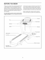
BEFORE YOU BEGIN
Thank you for selecting the revolutionary NordicTrack ®
C 1500 treadmill. The C 1500 treadmill offers an im-
pressive selection of features designed to make your
workouts at home more enjoyable and effective. And
when you're not exercising, the unique treadmill can be
folded up, requiring less than half the floor space of
other treadmills.
For your benefit, read this manual carefully before
using the treadmill. If you have questions after read-
ing this manual, please see the front cover of this man-
ual. To help us assist you, please note the product
model number and serial number before contacting us.
The model number and the location of the serial num-
ber decal are shown on the front cover of this manual.
Before reading further, please review the drawing
below and familiarize yourself with the labeled parts.
Tray
Console
Pulse Sensor
Handrail
Upright
Key/Clip
Walking Belt
Foot Rail
.-- Power Switch
-- Power Cord
Platform Cushion
Idler Roller
Adjustment Bolts
5

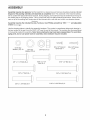
ASSEMBLY
Assembly requires two persons. Set the treadmill in a cleared area and remove all packing materials. Do not
dispose of the packing materials until assembly is completed. Note: The underside of the treadmill walking
belt is coated with high-performance lubricant. During shipping, some lubricant may be transferred to the top of
the walking belt or the shipping carton. This is normal and does not affect treadmill performance. If there is lubri-
cant on top of the walking belt, simply wipe off the lubricant with a soft cloth and a mild, non-abrasive cleaner.
Assembly requires the included hex key _]and your own Phillips screwdriver _ and adjustable
wrench _.
Use the drawings below to identify the assembly hardware. The number in parentheses below each drawing is
the key number of the part, from the PART LIST near the end of this manual. The number after the parentheses
is the quantity needed for assembly. Note: Some small parts may have been preassembled. To avoid dam-
aging parts, do not use power tools for assembly. Extra hardware may be included.
5/16" Star #8 x 1/2" Ground #8 x 3/4" Screw
Screw (9)-1 (1)-4
Washer (10)-10 3/8" Star 3/8" Nut (11)-2
Washer (12)-4
3/8" x 1 1/4" Bolt (8)-4 5/16" x 1 1/2"
Bolt (5)-4
3/8" x 2" Bolt (3)-1
5/16"x 2" Bolt (4)-4
3/8" x 2 3/4" Bolt (7)-4
3/8" x 13/4" Bolt (6)-1
5/16" x 3 3/4" Bolt (2)-2

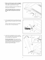
1. 1
Make sure that the power cord is unplugged.
Place a piece of cardboard below the rear of the
Frame (56) to protect the floor or carpet.
Attach the Left Wheel Cap (96) to the Base (97)
with two #8 x 3/4" Screws (1).
Attach the Right Wheel Cap (not shown) to
the right side of the Base (97) in the same
way.
97
96
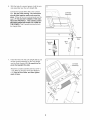
.
Pull the Upright Wire (84) and the Base Ground
Wire (94) through the indicated hole in the Base
(97).
Attach the Base Ground Wire (94) to the Base
(97) with a #8 x 1/2" Ground Screw (9).
84
Hole
\
94
.
identify the Left Upright (89), which is marked
with a "Left" sticker, Have a second person hold
the Left Upright near the Base (97).
See the inset drawing. Tie the wire tie in the
Left Upright (89) securely around the end of the
Upright Wire (84), Then, pull the other end of the
wire tie until the Upright Wire is routed com-
pletely through the Left Upright.
84
97

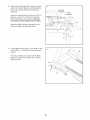
4. 4
HoldtheLeftUpright(89)againsttheBase
(97).Becarefulnottopinchthewires.Ifnec-
essary,positiontheBaseGroundWire(94)in
theholeinthesideoftheLeftUpright.Insert
two3/8"x23/4"Bolts(7)andtwo3/8"x11/4"
Bolts(8)withtwo3/8"StarWashers(12)into
theLeftUpright.
Partiallytightenthe3/8"x23/4"Bolts(7)and
the3/8"x 11/4"Bolts(8)untiltheheadsofthe
BoltstouchtheLeftUpright(89);do notfully
tightentheBoltsyet.
Attach the Right Upright (not shown) in the
same way. Note: There are no wires on the
right side.
12
97
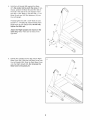
.
Identify the Left Base Cover (92) and the Right
Base Cover (93). Slide the Left Base Cover onto
the Left Upright (89). Slide the Right Base Cover
onto the Right Upright (90). Do not press the
Base Covers into place yet.
92

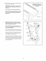
6. 6
Withthehelpofasecondperson,holdthecon-
soleassemblyneartheLeftUpright(89).
ConnecttheUprightWire(84)totheconsole
wire.Seetheinset drawing. The connectors
should slide together easily and snap into
place. If they do not, turn one connector and try
again. IF YOU DO NOT CONNECT THE CON-
NECTORS PROPERLY, THE CONSOLE MAY
BECOME DAMAGED WHEN YOU TURN ON
THE POWER. Then, remove the wire tie from
the Upright Wire.
Console
Assembly
Console
Wire_
84-__
Wire 84_
Tie_t!I
Console
Wire
----89
.
Insert the wires into the Left Upright (89) as you
set the console assembly on the Left Upright
and the Right Upright (90). Be careful not to
pinch the Upright Wire (84).
Attach the console assembly with four 5/16" x
1 1/2" Bolts (5) and four 5/16" Star Washers
(10). Start all four Bolts, and then tighten
each of them.
7
Console
Y
9

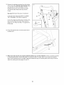
.
Identify the Left Handrail (87), which is marked
with a "Left" sticker. Slide the Left Handrail be-
tween the console assembly and the pulse
assembly.
Attach the Left Handrail (87) with two 5/16" x 2"
Bolts (4), a 5/16" x 3 3/4" Bolt (2), and three
5/16" Star Washers (10) as shown. Start all
three Bolts, and then tighten each of them.
Attach the Right Handrail (not shown) to the
console assembly as described above.
Console
Assembly
Pulse
Assembly
.
Firmly tighten the four 3/8" x 2 3/4" Bolts (7) and
the four 3/8" x 1 1/4" Bolts (8) (only one side is
shown).
Press the Left Base Cover (92) and the Right
Base Cover (93) onto the Base (97) until they
snap into place.
97
93
10

10. Make sure there is a piece of cardboard below
the rear of the Frame (56).
iMPORTANT: See page 14 and plug in the
power cord. Next, see page 16 and turn on
the power.
Then, press the 0 percent incline button.
When the Frame (56) stops moving, remove
the key from the console and unplug the
power cord.
10
56
iMPORTANT: Make sure
to follow all instructions
in this step
Cardboard
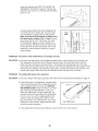
11. iMPORTANT: Before you begin this step,
make sure that you have read and followed
all the instructions in step 10.
Raise the Frame (56) to the position shown.
Have a second person hold the Frame until
this step is completed.
Orient the Storage Latch (53) so that the large
barrel and the latch knob are oriented as shown.
Attach the upper end of the Storage Latch (53)
to the bracket on the Frame (56) with a 3/8" x
1 3/4" Bolt (6) and a 3/8" Nut (11).
Attach the lower end of the Storage Latch (53) to
the Base (97) with a 3/8" x 2" Bolt (3) and a 3/8"
Nut (11). Note: It may be necessary to move the
Frame (56) back and forth to align the Storage
Latch with the Base.
11 °/
Latch
Knl
Large
Barrel
97
11
11

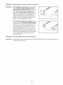
12. Remove the packaging material from the bottom
of the Frame (56). See the inset drawing. Make
sure that the 1/2" Rear Foot Nuts (111) are
threaded all the way onto the Rear Feet (60).
Turn the two Rear Feet all the way into the
Frame.
See step 10. Discard the piece of cardboard.
Lower the Frame (56) (see HOW TO LOWER
THE TREADMILL FOR USE on page 24).
If one of the Rear Feet (60) doesn't sit flat on the
floor, turn the Rear Foot until it does and then
tighten the 1/2" Rear Foot Nut (111) against the
Frame (56).
12
13. Press the Grommet (81) into the square hole in
the Base (97).
13
81
97
14. Make sure that all parts are properly tightened before you use the treadmill. If there are sheets of plastic
on the treadmill decals, remove the plastic. To protect the floor or carpet, place a mat under the treadmill.
Note: Extra hardware may be included. Keep the included hex key in a secure place; the hex key is used to
adjust the walking belt (see pages 26 and 27).
12

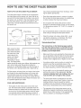
HOW TO USE THE CHEST PULSE SENSOR
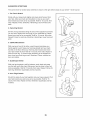
HOW TO PUT ON THE CHEST PULSE SENSOR
The chest pulse sensor consists of two components:
the chest strap and the sensor unit. Insert the tab on
one end of the chest strap into the hole in one end of
the sensor unit, as shown in the inset drawing. Press
the end of the sensor unit under the buckle on the
chest strap. The tab should be flush with the front of
the sensor unit.
Chest Strap
Tabs
Tab
Unit
Next, wrap the chest
pulse sensor around
your chest and attach
the other end of the
chest strap to the
sensor unit. Adjust
the length of the
chest strap, if neces-
sary. The chest pulse
sensor should be under your clothes, tight against your
skin, and as high under the pectoral muscles or
breasts as is comfortable. Make sure that the logo on
the sensor unit is facing forward and is right-side-up.
Pull the sensor unit away from your body a few inches
and locate the two electrode areas on the inner side
(the electrode areas are covered by shallow ridges).
Using saline solution such as saliva or contact lens so-
lution, wet both electrode areas. Return the sensor unit
to a position against your chest.
CARE AND MAINTENANCE
o Thoroughly dry the chest pulse sensor after each
use. The chest pulse sensor is activated when the
electrode areas are wetted and the chest pulse sen-
sor is put on; the chest pulse sensor shuts off when
it is removed and the electrode areas are dried. If
the chest pulse sensor is not dried after each use, it
may remain activated longer than necessary, drain-
ing the battery prematurely.
o Store the chest pulse sensor in a warm, dry place.
Do not store the chest pulse sensor in a plastic bag
or other container that may trap moisture.
Do not expose the chest pulse sensor to direct
sunlight for extended periods of time; do not expose
it to temperatures above 122° F (50° C) or below 14°
F (-10 ° C).
o Do not excessively bend or stretch the sensor unit
when using or storing the chest pulse sensor.
o Clean the sensor unit using a damp cloth--never
use alcohol, abrasives, or chemicals. The chest
strap may be hand washed and air dried.
TROUBLESHOOTING
The instructions on the following pages explain
how the chest pulse sensor is used with the con-
sole. If the chest pulse sensor does not function
properly, try the steps below.
Make sure that you are wearing the chest pulse sen-
sor as described at the left. Note: If the chest pulse
sensor does not function when positioned as de-
scribed, move it slightly lower or higher on your chest.
Use saline solution such as saliva or contact lens
solution to wet the two electrode areas on the
sensor unit. If heart rate readings do not appear until
you begin perspiring, rewet the electrode areas.
As you walk or run on the treadmill, position your-
self near the center of the walking belt. For the
console to display heart rate readings, the user
must be within arm's length of the console.
The chest pulse sensor is designed to work with
people who have normal heart rhythms. Heart rate
reading problems may be caused by medical
conditions such as premature ventricular contrac-
tions (pvcs), tachycardia bursts, and arrhythmia.
The operation of the chest pulse sensor can be
affected by magnetic interference caused by high
power lines or other sources. If it is suspected that
this is a problem, try relocating the treadmill.
13

OPERATION AND ADJUSTMENT
THE PRE-LUBRICATED WALKING BELT
Your treadmill features a walking belt coated with high-
performance lubricant. IMPORTANT: Never apply sil-
icone spray or other substances to the walking
belt or the walking platform. Such substances will
cause excessive wear.
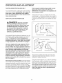
HOW TO PLUG IN THE POWER CORD
DAN GER: Improperconnection
of the equipment-grounding conductor in-
creases the risk of electric shock. Check with
a qualified electrician or serviceman if you
are unsure whether the product is properly
grounded. Do not modify the plug--if it will
not fit the outlet, have a proper outlet in-
stalled by a qualified electrician.
Your treadmill, like other electronic equipment, can be
damaged by sudden voltage changes in your home's
power. To decrease the risk of damaging your
treadmill, always use a surge suppressor with your
treadmill (see drawing 1 at the right). To purchase
a surge suppressor, see precaution 12 on page 3.
Use only a single-outlet surge suppressor that is
UL 1449 listed as a transient voltage surge sup-
pressor (TVSS). The surge suppressor must have a
UL suppressed voltage rating of 400 volts or less
and a minimum surge dissipation of 450 joules.
The surge suppressor must be electrically rated for
120 volts AC and 15 amps. There must be a moni-
toring light on the surge suppressor to indicate
whether it is functioning properly. Failure to use a
properly functioning surge suppressor could dam-
age the control system of the treadmill (see precau-
tion 13 on page 3).
This product must be grounded, if it should malfunc-
tion or break down, grounding provides a path of least
resistance for electric current to reduce the risk of elec-
tric shock. This product's power cord has an equip-
ment-grounding conductor and a grounding plug. Plug
the power cord into a surge suppressor, and plug
the surge suppressor into an appropriate outlet
that is properly installed and grounded in accor-
dance with all local codes and ordinances.
IMPORTANT: The treadmill is not compatible with
GFCI-equipped outlets.
This product is for use on a nominal 120-volt circuit
(see drawing 1). A temporary adapter may be used to
connect the surge suppressor to a 2-pole receptacle if
a properly grounded outlet is not available (see draw-
ing 2).
2
Grounded Outlet Box
_._, I _ Surge Suppressor
_'1 "-. Grounding Pin
Grounding Pin
Grounded Outlet
Grounding Plug
Grounded Outlet Box
Adapter
___. Surge Suppressor
Metal Screw
The temporary adapter should be used only until a
properly grounded outlet (see drawing 1) can be in-
stalled by a qualified electrician.
The green-colored rigid ear, lug, or the like extending
from the adapter must be connected to a permanent
ground such as a properly grounded outlet box cover.
The adapter must be held in place by a metal screw.
Some 2-pole receptacle outlet box covers are not
grounded. Contact a qualified electrician to deter-
mine if the outlet box cover is grounded before
using an adapter.
14

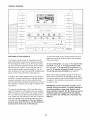
CONSOLEDIAGRAM
0000000
00000000
00000000
00000000
00000000
00000000
00000000
00000000
00000000
00000000
00000000
00000000
00000000
00000000
00000000
00000000
000000
O000QO0
O000QO0
O00000Q
O000QO0
0000000
O000QO0
0000000
00000000
00000000
O0000QO0
00000000
O0000QO0
00000000
00000000
00000000
FEATURES OFTHECONSOLE
The treadmill console offers an impressive array of
features designed to make your workouts more effec-
tive and enjoyable. When you use the manual mode,
you can change the speed and incline of the treadmill
with the touch of a button. As you exercise, the con-
sole will display instant exercise feedback. You can
even measure your heart rate using the handgrip pulse
sensor or the chest pulse sensor (see page 13).
In addition, the console features twenty-four onboard
workouts--six calorie workouts, six intensity workouts,
six speed workouts, and six incline workouts. Each
workout automatically controls the speed and incline of
the treadmill as it guides you through an effective exer-
cise session.
The console also features an iFit Live mode that en-
ables the treadmill to communicate with your wireless
network through an optional iFit Live module. With the
iFit Live mode, you can download personalized work-
outs, create your own workouts, track your workout re-
sults, race against other runners, and access many
other features. To purchase an iFit Live module at
any time, go to www.iFit.com or call the telephone
number on the front cover of this manual.
You can even listen to your favorite workout music or
audio books with the console's stereo sound system
while you exercise.
To turn on the power, see page 16. To use the man-
ual mode, see page 16. To use an onboard work-
out, see page 19. To use an iFit Live workout, see
page 20. To use the information mode, see page 22.
To use the stereo sound system, see page 23.
Note: The console can display speed and distance in
either miles or kilometers. To find which unit of mea-
surement is selected, see THE INFORMATION MODE
on page 22. For simplicity, all instructions in this man-
ual refer to miles.
IMPORTANT: If there are sheets of plastic on the
console, remove the plastic. To prevent damage to
the walking platform, wear clean athletic shoes
while using the treadmill. The first time you use the
treadmill, observe the alignment of the walking
belt, and center the walking belt if necessary (see
page 27).
15

HOW TO TURN ON THE POWER HOW TO USE THE MANUAL MODE
iMPORTANT: if the treadmill has been exposed to
cold temperatures, allow it to warm to room tem-
perature before turning on the power, if you do not
do this, you may damage the console displays or
other electrical components.
Plug in the power cord (see
page 14). Next, locate the
power switch on the tread-
mill frame near the power
cord. Press the power
switch into the reset
position.
Reset_
iMPORTANT: The console features a display demo
mode, designed to be used if the treadmill is dis-
played in a store, if the displays light as soon as
you plug in the power cord and press the power
switch into the reset position, the demo mode is
turned on. To turn off the demo mode, hold down
the Stop button for a few seconds, if the displays
remain lit, see THE iNFORMATiON MODE on page
22 to turn off the demo mode.
Next, stand on the foot rails
of the treadmill. Find the
clip attached to the key and
slide the clip onto the waist-
band of your clothes. Then,
insert the key into the con-
sole. After a moment, the
displays will light. IMPOR-
TANT: In an emergency,
Clip
the key can be pulled from the console, causing
the walking belt to slow to a stop. Test the clip by
carefully taking a few steps backward; if the key is
not pulled from the console, adjust the position of
the clip.
1. insert the key into the console.
See HOW TO TURN ON THE POWER at the left.
2. Select the manual mode.
Press the Manual button on the console. If you are
not connected to iFit Live, the manual mode will be
selected automatically.
3. Start the walking belt.
To start the walking belt, press the Start button, the
Speed increase button, or one of the numbered 1
Step Speed buttons.
If you press the Start button or the Speed increase
button, the walking belt will begin to move at 1
mph. As you exercise, change the speed of the
walking belt as desired by pressing the Speed in-
crease and decrease buttons. Each time you press
one of the buttons, the speed setting will change by
0.1 mph; if you hold down the button, the speed
setting will change in increments of 0.5 mph. Note:
After you press the button, it may take a moment
for the walking belt to reach the selected speed
setting.
If you press one of the numbered 1 Step Speed
buttons, the walking belt will gradually change
speed until it reaches the selected speed setting.
To select a speed setting that includes a decimal--
such as 3.5 mph--press two numbered buttons in
succession. For example, to select a speed setting
of 3.5 mph, press the 3 button and then immedi-
ately press the 5 button.
To stop the walking belt, press the Stop button.
The time will begin to flash in the display. To restart
the walking belt, press the Start button or the
Speed increase button.
16

.
.
Change the incline of the treadmill as desired.
To change the inclineof the treadmill, press the
Incline increase or decrease button or one of the
numbered 1 Step Incline buttons. Each time you
press one of the buttons, the treadmill will gradu-
ally adjust to the selected incline setting.
Follow your progress with the displays.
As you walk or run on the treadmill, the display can
show the following workout information:
o The elapsed time
o The distance that you have walked or run
o The matrix
o The workout intensity bar
o The approximate number of calories you have
burned
o The incline level of the treadmill
o The number of vertical feet you have climbed
o The speed of the walking belt
o Your heart rate (see step 6 on page 18)
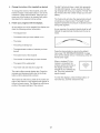
The matrix offers several display tabs. Press the
increase and decrease button next to the Enter
button until the desired tab is shown.
The Incline tab will show a profile of the incline set-
tings of the workout. A new segment will appear at
the end of each minute. The Speed tab will show a
profile of the speed settings of the workout.
The My Trail tab will show a track that represents
1/4 mile (400 meters). As you exercise, the flash-
ing rectangle will show your progress. The My Trail
tab will also show the number of laps you are com-
pleting.
The Calorie tab will show the approximate amount
of calories you have burned. The height of each
segment represents the amount of calories burned
during that segment.
As you exercise, the workout intensity level bar will
indicate the approximate intensity level of your ex-
ercise.
Press the Home button to return to the default
menu (see THE INFORMATION MODE on page
22 to set the default menu). If necessary, press the
Home button again.
When a wireless iFit Live
module is connected, the
wireless symbol at the top of
the display will show the
strength of your wireless sig-
nal. Four arcs indicate full
signal strength.
To reset the displays, press the Stop button, re-
move the key, and then reinsert the key.
17

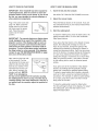
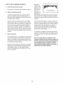
6. Measure your heart rate if desired.
Note: if you use the handgrip pulse sensor and
the chest pulse sensor at the same time, the
console will not display your heart rate accu-
rately. For information on the chest pulse sensor,
see page 13.
Before using the
handgrip pulse
sensor, remove
the sheets of
plastic from the
metal contacts
on the pulse bar.
In addition, make
sure that your
hands are clean.
Contacts
To measure your heart rate, stand on the foot
rails and hold the pulse bar with your palms on the
metal contacts for approximately ten seconds;
avoid moving your hands. When your pulse is
detected, your heart rate will be shown, For the
most accurate heart rate reading, continue to
hold the contacts for about 15 seconds.
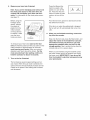
7. Turn on the fan if desired.
The fan features several speed settings and an
auto mode. When the auto mode is selected, the
speed of the fan will automatically increase and de-
crease as the speed of the walking belt increases
and decreases.
.
Press the Manual fan
button to select a fan
speed or to turn off the
fan. Press the Auto fan
button to select the auto
mode or to turn off the
fan.
RUT(D Mf=/NURL /
Pivot the fan lever upward or downward to direct
the airflow from the fan.
If the fan is on when the walking belt is stopped,
the fan will turn off automatically after a few min-
utes.
When you are finished exercising, remove the
key from the console.
Step onto the foot rails, press the Stop button, and
adjust the incline of the treadmill to 0 percent.
The incline must be at 0 percent or you may
damage the treadmill when you fold it to the
storage position. Next, remove the key from the
console and put it in a secure place.
When you are finished using the treadmill, press
the power switch into the off position and unplug
the power cord. IMPORTANT: If you do not do
this, the treadmill's electrical components may
wear prematurely.
18

HOW TO USE AN ONBOARD WORKOUT
1. Insert the key into the console.
See HOW TO TURN ON THE POWER on page 16.
2. Select an onboard workout.
To select an onboard workout, press the Calorie
button, the Intensity button, the Speed button, or
the Incline button repeatedly until the desired work-
out appears in the display.
When you select an onboard workout, the display
will show the duration, the distance, and the name
of the workout. After a few seconds, the display will
show the maximum speed and incline settings of
the workout. In addition, a profile of the speed set-
tings of the workout will appear in the matrix. If you
select a calorie workout, the approximate number of
calories you will burn will appear in the name of the
workout.
3. Start the workout.
Press the Start button or the Speed increase button
to start the workout. A moment after you press the
button, the treadmill will automatically adjust to the
first speed and incline settings of the workout. Hold
the handrails and begin walking.
Each workout is divided into segments. One speed
setting and one incline setting are programmed for
each segment. Note: The same speed setting
and/or incline setting may be programmed for con-
secutive segments.
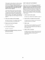
During the
workout, the
profiles on the
speed and in-
cline tabs will
show your
progress. The
flashing seg-
==:--._->-=_WEL.-_:;:.=_.-......-".-'-'===
Current Segment
ment of the profile represents the current segment
of the workout. The height of the flashing segment
indicates the speed or incline setting for the current
segment.
At the end of each segment, a series of tones will
sound and the next segment of the profile will begin
to flash. If a different speed and/or incline setting is
programmed for the next segment, the speed
and/or incline setting will flash in the display and
the treadmill will automatically adjust to the new
speed and/or incline setting.
The workout will continue in this way until the last
segment of the profile flashes in the display and the
last segment ends. The walking belt will then slow
to a stop.
Note: The calorie goal is an estimate of the
number of calories that you will burn during the
workout. The actual number of calories that you
burn will depend on your weight. In addition, if
you manually change the speed or incline of
the treadmill during the workout, the number of
calories you burn will be affected.
19

If the speed or incline setting is too high or too low
at any time during the workout, you can manually
override the setting by pressing the Speed or
Incline buttons; however, when the next segment
of the workout begins, the treadmill will auto-
matically adjust to the speed and incline set-
tings for the next segment.
To stop the workout at any time, press the Stop
button. The time will begin to flash in the display.
To resume the workout, press the Start button or
the Speed increase button. The walking belt will
begin to move at 1 mph. When the next segment of
the workout begins, the treadmill will automatically
adjust to the speed and incline settings for the next
segment.
4. Follow your progress with the displays.
See step 5 on page 17. The display will show the
time remaining instead of the elapsed time.
5. Measure your heart rate if desired.
See step 6 on page 18.
6. Turn on the fan if desired.
.
See step 7 on page 18.
When you are finished exercising, remove the
key from the console.
See step 8 on page 18.
HOW TO USE AN IFIT LIVE WORKOUT
Note: To use an iFit Live workout, you must have an
optional iFit Live module. To purchase an iFit Live
module at any time, go to www.iFit.com or call the
telephone number on the front cover of this man-
ual. You must also have access to a computer with a
USB port and an internet connection. In addition, you
must have access to a wireless network including an
802.1 lb router with SSID broadcast enabled (hidden
networks are not supported). An iFit.com membership
is also required.
1. Insert the key into the console.
See HOW TO TURN ON THE POWER on page 16.
2. Insert the iFit Live module into the console.
To insert the iFit Live module, see the instructions
included with the iFit Live module.
3. Select a user.
If more than one user is registered, you can switch
users in the iFit Live main screen. Press the in-
crease and decrease buttons next to the Enter but-
ton to select a user.
4. Select an iFit Live workout.
To select an iFit Live workout, press one of the iFit
Live buttons. Before a workout will download, you
must add the workout to your queue on
www.iFit.com.
2O
Page is loading ...
Page is loading ...
Page is loading ...
Page is loading ...
Page is loading ...
Page is loading ...
Page is loading ...
Page is loading ...
Page is loading ...
Page is loading ...
Page is loading ...
Page is loading ...
Page is loading ...
Page is loading ...
Page is loading ...
Page is loading ...
-
 1
1
-
 2
2
-
 3
3
-
 4
4
-
 5
5
-
 6
6
-
 7
7
-
 8
8
-
 9
9
-
 10
10
-
 11
11
-
 12
12
-
 13
13
-
 14
14
-
 15
15
-
 16
16
-
 17
17
-
 18
18
-
 19
19
-
 20
20
-
 21
21
-
 22
22
-
 23
23
-
 24
24
-
 25
25
-
 26
26
-
 27
27
-
 28
28
-
 29
29
-
 30
30
-
 31
31
-
 32
32
-
 33
33
-
 34
34
-
 35
35
-
 36
36


NordicTrack c1500 831.24992.0 User manual
- Category
- Treadmills
- Type
- User manual
- This manual is also suitable for
Ask a question and I''ll find the answer in the document
Finding information in a document is now easier with AI
Related papers
-
NordicTrack NTL15907.0 User manual
-
-
-
-
-
-
ProForm C 2500 User manual
-
-
-
Other documents
-
Epic Tl 2710 Treadmill User manual
-
FreeMotion SFTL15510.0 User manual
-
-
-
-
Pro-Form 985 Audio Trainer User manual
-
-
-
-
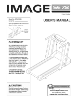 Image IMTL07800 Owner's manual
