1
41473-01 12/6/2001
Installation and Operation Manual
CONTENTS
Important Information ...................................................................................................................................... 2
Step 1 - Getting Ready ..................................................................................................................................... 2
Step 2 - Choosing the Fan Site ......................................................................................................................... 3
Step 3 - Installing the Ceiling Plate ................................................................................................................... 6
Step 4 - Assembling the Fan............................................................................................................................. 6
Step 5 - Wiring the Fan .................................................................................................................................... 8
Step 6 - Assembling the Fan Blades .................................................................................................................. 9
Step 7 - Operating Your Hunter Fan ............................................................................................................... 10
Step 8 - Installing Light Fixture ....................................................................................................................... 11
Step 9 - Installing Light Fixture ....................................................................................................................... 11
Step 10 - Wiring the Light Fixture................................................................................................................... 12
Step 11 - Installing the Globes........................................................................................................................ 12
Troubleshooting.............................................................................................................................................. 14
Your new Hunter ceiling fan is an addition to your home or office that will provide comfort and performance for
many years. This manual gives you complete instructions for installing and operating your fan.
We are proud of our work. We appreciate the opportunity to supply you with the best ceiling fan available any-
where in the world.
Before installing your fan, record the following information for your records and warranty assistance. Please refer
to the carton and the Hunter nameplate (located on top outside fan motor housing) for the proper information.
Model Name __________________
Catalog No. ___________________
Serial No. _____________________
Date Purchased ________________
Where Purchased ______________
_____________________________
®

2
41473-01 12/6/2001
GATHERING THE TOOLS
You will need the following tools for installing the fan:
• Electric drill with 9/64" bit
• Standard screwdriver
• Phillips-head screwdriver
• Wrench or pliers
PREPARING THE FAN SITE
STEP 1 - GETTING READY
IMPORTANT
INFORMATION
CAUTIONS
• Read entire booklet carefully before begin-
ning installation and save these instructions.
• To reduce the risk of personal injury, attach
the fan directly to the support structure of
the building according to these instructions,
and use only the hardware supplied.
WARNINGS
• To avoid possible electrical shock, before in-
stalling your fan, disconnect the power by
turning off the circuit breakers to the outlet
box and associated wall switch location. If you
cannot lock the circuit breakers in the off po-
sition, securely fasten a prominent warning
device, such as a tag, to the service panel.
• All wiring must be in accordance with national
and local electrical codes and ANSI/NFPA 70.
If you are unfamiliar with wiring, you should
use a qualified electrician.
• To reduce the risk of personal injury, do not
bend the blade attachment system when in-
stalling, balancing, or cleaning the fan. Never
insert foreign objects between rotating fan
blades.
• To reduce the risk of fire, electrical shock, or
motor damage, do not use a solid-state speed
control with this fan.
DO YOU NEED HELP?
To install a ceiling fan, be sure you can do the following:
• Locate ceiling joist or other suitable support in ceil-
ing.
• Drill holes for and install wood screws.
• Identify and connect electrical wires.
• Lift 40 pounds.
If you need help installing the fan, your fan dealer can
direct you to a licensed installer or electrician.
These guidelines are designed to help you select the best
location for your fan and to prepare the site prior to
installing the fan. Proper ceiling fan location and attach-
ment to the building structure are essential for safety,
reliable operation, maximum efficiency, and energy sav-
ings.
CAUTIONS
• Read this entire guide and the manufacturer’s instal-
lation instructions carefully before beginning.
• To reduce the risk of personal injury, attach the fan
directly to the support structure of the building ac-
cording to these guidelines, and use only the hard-
ware supplied with the fan.
• The fan mounting must be able to support the full
weight of the fan and light kit.
WARNINGS
• To avoid possible electrical shock, before inspecting
and preparing the site, disconnect the power by turn-
ing off the circuit breakers to the outlet box or lead
cables and associated wall switch location. If you can-
not lock the circuit breakers in the off position, se-
curely fasten a prominent warning device, such as a
tag, to the service panel.
• All wiring must be in accordance with national and
local electrical codes and ANSI/NFPA 70-1993. Any-
one who is unfamiliar with wiring should contact a
qualified electrician.
handy for identifying parts during installation; the dia

3
41473-01 12/6/2001
gram indicates the step in which each part is used.
Within the room where you want to install the fan,
choose a fan site where
• No object can come in contact with the rotating fan
blades during normal operation
• The fan blades are at least seven feet (7') above the
floor and the ceiling is at least eight feet (8') high
• The fan blades have no obstructions to air flow, such
as walls or posts, within 30 inches (30") of the fan
blade tips
• The fan is directly below a joist or support brace
that will hold the outlet box and the full weight of
the fan
See Figure 2a for the minimum mounting distances.
8' Minimum
Ceiling Height
7' Minimum
To Floor
30"
From Wall
or Nearest
Obstruction
Figure 2a - Fan Clearances
STEP 2 - CHOOSING THE
FAN SITE
USING AN EXISTING FAN SITE
If you are preparing a new fan site, go to the next sec-
tion, “Preparing a New Fan Site.”
If you plan to use an existing fan site, complete the fol-
lowing checklist for the support brace, ceiling hole, out-
let box, and wiring. If you cannot check off every item,
see the next section, “Preparing a New Fan Site,” for
instructions on properly preparing the site for your new
fan.
Figure 2b - Existing Fan Site
Wood
Screw
Washer
Approved
Connector
Support Brace
Ceiling Joist
Ceiling
Outlet
Box
If your existing fan site is suitable, refer to the
manufacturer’s installation manual for instructions on
how to install your ceiling fan and any attachments.
FAN SUPPORT SYSTEM
Fan must attach directly to building structure
Fan support system must hold full weight of fan and
light kit
CEILING HOLE
Outlet box clearance hole directly below the joist or
support brace
OUTLET BOX
UL-approved octagonal
4"x
1-
1
/2" outlet box (or as
specified by manufacturer)
Outlet box secured to joist or support brace by wood
screws and washers through inner holes of outlet box
Outer holes of outlet box aligned with joist or sup-
port brace
Bottom of outlet box recessed a minimum of 1/16"
into ceiling
WIRING
Electrical cable secured to outlet box by approved
connector
Six inches (6") of lead wires extend from outlet box
See Figure 2b for an adequate existing fan site.

4
41473-01 12/6/2001
To prepare the fan site follow four steps:
Step 1: Cutting the Ceiling Hole
Step 2: Installing the Support Brace (if necessary)
Step 3: Installing the Outlet Box
Step 4: Preparing the Wiring
STEP 1: CUTTING THE CEILING HOLE
1. Locate the site for the hole directly below the joist or
support brace that will hold the outlet box and fan.
2. Cut a four inch (4") diameter hole through the dry-
wall or plaster of the ceiling as shown in Figure 2c.
You will use the hole to install the support brace and
outlet box.
STEP 2: INSTALLING THE
SUPPORT BRACE
If there is a ceiling joist directly above the hole which
will allow the outlet box to be recessed a minimum of 1/
16"in the ceiling, go to Step 3: Installing the Outlet Box.
If there is not an adequate ceiling joist available, do the
following:
1. Attach a 2"x 4" support brace between two joists.
The support brace must allow the bottom of the
outlet box to be recessed a minimum of 1/16" into
the ceiling. See Figure 2c.
2. Check the support brace to ensure it will support
the full weight of the fan and light kit.
PREPARING A NEW FAN SITE
Figure 2c - Ceiling Hole and Support
Brace
Ceiling
4"
Diameter
Ceiling Hole
Support Brace
Ceiling Joist
Wood Screw
Washer
Support Brace
Outlet
Box
1/16" Recess
Figure 2d - Installing Outlet Box
STEP 3: INSTALLING THE OUTLET BOX
1. Obtain a UL-approved octagonal 4"x 1-
1
/2" outlet
box, plus two #8 x 1-
1
/2" wood screws and washers,
available from any hardware store or electrical sup-
ply house.
Approved
Connector
Wire Leads
Figure 2e - Wiring for Fan
STEP 4: PREPARING THE WIRING
1. Make sure the circuit breakers to the fan supply line
leads and associated wall switch location are turned
off. If you cannot lock the circuit breakers in the off
position, securely fasten a prominent warning device,
such as a tag, to the service panel.
2. Thread the fan supply line through the outlet box so
that the fan supply line extends at least six inches
(6") beyond the box as shown in Figure 2e.
3. Attach the fan supply line to the outlet box with an
approved connector, available at any hardware store
or electrical supply house. Refer to Figure 2e.
4. Make certain the wiring meets all national and local
standards and ANSI/NFPA 70.
2. Orient the outlet box so that both the inner and outer
holes in the box align with the joist or support brace.
3. Drill pilot holes no larger than the minor diameter of
the wood screws (5/64") through the inner holes of
the outlet box.
4. Attach the outlet box directly to the support brace or
joist with two #8 x 1-
1
/2" wood screws and washers.
The bottom of the outlet box must be recessed a mini-
mum of 1/16" into the ceiling as shown in Figure 2d.

5
41473-01 12/6/2001
INSTALLER’S CHOICE®
This patented 3-position mounting system provides you maximum installation flexibility and ease. You can install
your Hunter fan in one of three ways. The steps in this manual include specific instructions for the fan mounting
method of your choice.
Flush Mounting (Figure 2f) fits close to the ceiling, for
low ceilings less than 8 feet high.
Standard Mounting (Figure 2g) hangs from the ceil-
ing by a connector pipe (included), for ceilings 8 feet or
higher. For ceilings higher than eight feet, you can pur-
chase Hunter extension rods. All Hunter fans use sturdy
3/4" diameter pipe to assure stability and wobble-free
performance.
Figure 2h - Angle Mounting
Figure 2g - Standard Mounting
Figure 2f - Flush Mounting
10"
12"
34° Max
Pitch
12
8
Angle Mounting (Figure 2h) hangs from a vaulted or
angled ceiling.

6
41473-01 12/6/2001
STEP 4 - ASSEMBLING
THE FAN
Use the Step 4 instructions for the type of mounting you
have selected: standard, angle, or flush.
STANDARD AND ANGLE MOUNTING
For Standard 8-foot Ceilings and Higher
1. Insert the pipe through the canopy as shown in Fig-
ure 4a. Feed wires from the fan through the pipe.
2. Screw pipe into fan assembly until tight. IMPORTANT!
Tighten pipe setscrew as shown in Figure 4a.
Figure 4a - Inserting Pipe through
Canopy
Pipe
Canopy
Pipe
Setscrew
Figure 3c - Attaching Ceiling Plate to
2 x 4 Brace
2 x 4 Brace
Ceiling Joist
Ceiling
Outlet Box
Ceiling
Plate
Flat
Washer
3" Wood
Screw
5. Place a flat washer on each of the two 3" screws and
pass the screws through the slotted holes in the ceil-
ing plate as shown in Figure 3c.
6. Tighten the screws into the 9/64" pilot holes; do not
use lubricants on the screws. Do not overtighten.
STEP 3 - INSTALLING THE
CEILING PLATE
1. Drill two pilot holes into the wood support structure
through the outermost holes on the outlet box. The
pilot holes should be 9/64" in diameter.
2. Thread the lead wires from the outlet box through
the hole in the middle of the ceiling plate.
3. Your fan comes with two neoprene noise isolators.
Position the isolators between the ceiling plate and
ceiling by inserting the raised areas on each isolator
into the holes in the ceiling plate. Refer to Figure 3a.
Figure 3a - Adding Isolators to Ceiling
Plate
Figure 3b - Correct Position of Ceiling
Plate for Angle Mounting
Ceiling Plate
Hooks
Isolators
Ceiling
Plate
4. Align the slotted holes in the ceiling plate with the
pilot holes in the wood support structure. Note: The
isolation pads should be flush against the ceiling.
For Angle Mounting Only: Be sure to orient the
ceiling plate so that the two hooks point up towards
the ceiling peak as shown in Figure 3b. Note: You
will use the hooks to support the fan during STEP 5 -
WIRING THE FAN.
CAUTION
The pipe has a special coating on the threads. Do
not remove this coating; the coating prevents the
pipe from unscrewing. Once assembled, do not
remove the pipe.

7
41473-01 12/6/2001
FLUSH MOUNTING
For Low Ceilings
1. Position the three rubber spacers over the
threaded holes in the motor adapter as shown in
Figure 4b
Figure 4c - Placing Canopy and
Washer Over Adapter
Assembly
Washer
Canopy
Adapter
Top of Fan
Figure 4e - Attaching Canopy to Fan
Assembly
Assembly
Washer
Adapter
Threaded
Hole
Figure 4d - Positioning Assembly
Washer Slots over Threaded Holes
4. Position the slots in the assembly washer over the
threaded holes in the adapter as shown in Figure 4c.
NOTE: Upon completing step 3, the slots in the as-
sembly washer, the rubber spacers and the threaded
holes in the adapter should be aligned.
Assembly Screw
and Lockwasher
5. Insert the three assembly screws and lockwashers
through the spacers and into the adapter.
6. Attach the canopy tightly to the fan assembly with
three assembly screws and lockwashers as shown in
Figure 4d.
2. Fit the canopy over the motor hanger adapter as
shown in Figure 4c. Make sure the canopy fits snugly
against the fan assembly with no space between the
pieces.
3. You will find a large assembly washer included with
the fan. Place the washer over the adapter and canopy
as shown in Figure 4d.
Figure 4b - Placing Rubber Spacers
Threaded
hole
Rubber
Spacer
Motor
Adapter

8
41473-01 12/6/2001
STEP 5 - WIRING THE FAN
1. Disconnect the power by turning off the circuit break-
ers to the outlet box and associated wall switch loca-
tion.
2. Tilt and hang the assembled fan from the ceiling plate
hooks. Slip two rectangular canopy slots over ceiling
plate hooks as shown in Figures 5a and 5b.
Note: To hang the fan you must tilt the canopy to an
almost vertical position so the canopy slots come
down over the ceiling plate hooks.
3. You can use either one or two wall switches to con-
trol the fan and/or lights separately. Use connection
1 below to
• control the light with a wall switch and the fan
with a chain pull (one wall switch required)
• control the light with a chain pull and the fan with
a wall switch (one wall switch required)
• control the light with one wall switch and the fan
with another (two wall switches required)
Use connection 2 below if there is no separate wall
switch power wire for the light kit.
Figure 5b - Assembled Fan Hanging
from Ceiling Plate Hooks
Ceiling
Plate
Figure 5a - Attaching Slots on Canopy
to Ceiling Plate Hooks
Bare or Green
Approved
Connectors
Power
Wires
In
Ceiling
White
White
Black
Black/White
1
2
Connections:
Black
Wall Switch Wire For
Separate Control of Light Kit
Ceiling
Plate
Outlet Box
2 x 4 Brace
Green Ground
Wire from Hanger
Pipe (standard and
angle mounting only)
Green Ground
Wire from Ceiling
Plate (present with
standard, angle, and
flush mounting)
3 Wires
From Fan
(Note: Wall switch
must be acceptable
as a general-use
switch.)
Connect Blk/Wht Wire from fan
to Wall Switch Wire for separate
control of light, or
Connect Blk/Wht Wire from fan
to Ceiling Black Wire if there
is no separate Wall Switch Wire
for the light kit.
1
2
4. Connect the wires as shown in Figure 5c. To connect
the wires, twist the bare metal leads together. Place
a wire nut over the intertwined length of wire and
twist clockwise until tight as shown.
CAUTION
Be sure no bare wire or wire strands are visible
after making connections.
5. Separate the connected wires by placing the green
and white wires on one side of the outlet box and
the black and the black/white wires on the other side
of the outlet box.
6. Turn the connectors upward. Push the wires gently
into the outlet box.
Figure 5c - Wiring Diagram

9
41473-01 12/6/2001
STEP 6 - HANGING THE
FAN
Sub-steps 1 and 2 apply to Flush, Standard, and Angle
mounting. Sub-step 3 applies to Standard and Angle
mounting only.
1. Swing the fan up so as to align the canopy screw
holes with the mounting holes on the ceiling plate.
Refer to Figure 6a.
2. Install and tighten the two #10-32 x 1/2" mounting
screws.
3. For Standard and Angle Mounting only: In addi-
tion to sub-steps 1 and 2, lift the fan housing to-
wards the ceiling and rotate the fan until each canopy
tab engages a groove in the hanger ball as shown in
Figure 6b.
Note: If the tabs are already engaged, do not rotate.
WARNING
Failure to complete sub-steps 1 through 3 could
cause fan to fall. (Sub-step 3 not applicable for
flush mounting.)
Figure 6a - Attaching Canopy to
Ceiling Plate
Ceiling
Plate
Canopy
Figure 6b - Canopy Tabs and Grooves
in Hanger Ball
Groove in
Hanger
Ball
Canopy
Tab
Groove in
Hanger Ball

10
41473-01 12/6/2001
Figure 7a - Inserting Grommet into
Fan B•lade
Figure 7b - Attaching Fan Blade to
Blade Iron
Figure 7c - Attaching Fan Blade to
Blade Iron using Decorative Medallion
Builder's fans use several styles of fan blade irons (brack-
ets that hold the blade to the fan).
1. Your fan may include blade grommets (see Parts List).
If your fan has grommets, insert them by hand into
the holes as shown in Figure 7a.
2. Attach each blade to blade iron using three blade
assembly screws as shown in Figure 7b. Some fans
feature a decorative medallion as well as a blade
iron. Insert the assembly screws into the blade iron,
through the blade and into the medallion, with the
blade sandwiched between the blade iron and me-
dallion as shown in Figure 7c.
If you used grommets, the blades may appear slightly
loose after screws are tightened. This is normal.
3. Remove the blade mounting screws and rubber ship-
ping bumpers from the motor.
4. For each blade, insert one blade mounting screw
through the blade iron as shown in Figure 6d, and
attach lightly to the fan. Insert the second blade
mounting screw, then securely tighten both mount-
ing screws.
STEP 7 - ASSEMBLING FAN BLADES
Grommet
Fan
Blade
Medallion
Blade
Iron
Figure 7d - Attaching Blade Irons to
Hub of Fan Assembly

11
41473-01 12/6/2001
STEP 9 - INSTALLING LIGHT FIXTURE
STEP 8 - OPERATING YOUR HUNTER FAN
1. Turn on electrical power to the fan.
2. The pull chain controls power to the fan. The chain has four settings in sequence: High, Medium, Low and Off.
• Pull the chain slowly to change settings.
• Release slowly to prevent the chain from recoiling into the blades.
• The chain uses a breakaway connector that separates if the chain is jerked. If this happens, simply reinsert the
chain into the connector.
3. Ceiling fans work best by blowing air downward (counterclockwise blade rotation) in warm weather to cool the
room with a direct breeze. In winter, having the fan draw air upward (clockwise blade rotation) will distribute
the warmer air trapped at the ceiling around the room without causing a draft.
To change the direction of air flow, turn the fan off and let it come to a complete stop. Slide the reversing switch
on the fan to the opposite position as shown in Figure 8b. Restart fan.
4. If your fan wobbles when operating, use the enclosed balancing kit and instructions to balance the fan.
Figure 8a - Air Flow Patterns
Pull
Chain
Reversing
Switch
Figure 8b - Pull Chain and Reversing
Switch
Your Hunter fan may include an integrated light fixture. If you are not installing a light fixture, turn directly to
OPERATING YOUR HUNTER FAN for additional instructions.
Information for wiring and installing all included Hunter light fixtures are included in the following section “Attach-
ing Light Fitter to Switch Housing,” .
Figure 9a - Fan Switch Housing
ATTACHING LIGHT FITTER TO SWITCH HOUSING
Note: Refer to Figures 9a and 9b for the steps below.
1. Remove the switch housing cover from the switch housing by removing the three #6-32 housing assembly
screws from the sides of the switch housing. See Figure 9b.
Note: Do not discard the screws or cap. You will need the screws later in the installation. You will need the cap
if you remove the light fixture in the future.
Figure 9b - Removing Switch Housing
Cover
Switch
Housing
Cover
Switch
Housing
Housing
Assembly
Screw

12
41473-01 12/6/2001
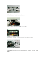
INSTALLING INCLUDED INTEGRAL LIGHT FIXTURE
1. In the switch housing assembly you will find a plug
connector: One two-wire connector. The connec-
tor will have a black with white stripe wire and a
white wire.
2. Locate the white wire and the black wire coming from
the light fixture.
3.
Connect the upper plug connector from the motor to
the lower plug connector in the light assembly. See
Figure 10a.
Note: Both plug connectors are polarized and will only
fit together one way. Make sure that both connec-
tors are properly aligned before connecting them to-
gether. Incorrect connection could cause improper op-
eration and damage to the product.
4. Place the lower switch housing assembly over the
upper switch housing. Align the side screw holes in
the upper and lower switch housings. Attach the light
to the upper switch housing with three #6-32 hous-
ing assembly screws.
White Wire
from Light
Fixture
Black Wire
from Light
Fixture
Light
Fixture
Figure 10a - Wiring Light Fixture to
Fan
Lower Plug
Connector
Upper Plug
Connector
Upper Switch
Housing
STEP 10 - WIRING THE LIGHT FIXTURE
WARNING
• To avoid possible electrical shock, before install-
ing light fixtures, disconnect power by turning off
the circuit breakers both to the outlet box and to
its associated wall switch location. If you cannot
lock the circuit breakers in the off position, se-
curely fasten a prominent warning device, such
as a tag, to the service panel.
• Connect house wiring to the fan before attach-
ing the light fixture to the fan.
• All wiring must be in accordance with national
and local electrical codes and ANSI/NFPA 70. If
you are unfamiliar with wiring, you should use a
qualified electrician.
INSTALLING INCLUDED SINGLE-GLOBE LIGHT FIXTURE
1. Remove the plug cap from the lower switch housing.
Note: Do not discard the plug cap. You will need this
if you remove the light fixture in the future.
2. Locate the two wires in the lower switch housing
labeled “Connect Light Here” or “For Light Use”.
One will be white, the other black/white. Unscrew
the wire nuts counterclockwise to expose the bare
metal leads.
3. Locate the white wire and the black wire coming from
the light fixture.
4. Thread the two wires from the light fixture through
the center hole in the lower switch housing.
5. Screw the fixture into the lower switch housing.
Thread the lockwasher and nut provided over the
wires. Making sure the light fixture mounting screw
holes are aligned; hold the light fixture and tighten
the nut on the inside of the lower switch housing.
Insert and tighten the two #6-32 sems light fixture
mounting screws.
6. Connect the black wire from the light fixture to the
black/white wire from the lower switch housing. See
Figure 10b.
Connect the white wire from the light fixture to the
white wire from the lower switch housing. See Fig-
ure 10b.
To fasten the wires, twist the two bare leads together.
Place a wire nut over the intertwined length of wire
and twist clockwise until tight.
7. Connect the upper plug connector from the motor
to the lower plug connector in the lower switch hous-
ing assembly. See Figure 10a.
Note: Both plug connectors are polarized and will
only fit together one way. Make sure that both con-
nectors are properly aligned before connecting them
together. Incorrect connection could cause improper
operation and damage to the product.
8. Place the lower switch housing assembly over the
upper switch housing. Align the side screw holes in
the upper and lower switch housings. Attach the
lower switch housing to the upper switch housing
with three #6-32 x 3/8" housing assembly screws.
See Figure 10a.
CAUTION
Be sure no bare wire or wire
strands are visible after making
connections.

13
41473-01 12/6/2001
Black/White
Wire from
Switch Housing
White Wire
from Switch
Housing
Wire Nut
White Wire
from Light
Fixture
Black Wire
from Light
Fixture
Light
Fixture
Figure 10b - Wiring Light Fixture to Fan
Globe
Thumbscrew
Bulb
Figure 11b - Single-Globe Fixture
INSTALLING SINGLE-GLOBE FIXTURE BULB AND
GLOBE
Refer to Figure 11b.
1. Install light bulbs.
2. Insert the globe around the bulb and into the fix-
ture. Install and tighten thumbscrews manually. Do
not overtighten.
Figure 11a - Multi-Light Fixture
Cup
Globe
Silencer
Band
Thumb-
screw
Instructions follow for installing globes for all included light fixtures.
INSTALLING INTEGRAL MULTI-LIGHT FIXTURE BULBS
AND GLOBES
Refer to Figure 11a.
1. Place silencer band around the neck of each globe.
2. Insert globe in cup.
3. Install and tighten thumbscrews manually. Do not
overtighten.
4. Install bulbs.
STEP 11 - INSTALLING THE GLOBES

14
41473-01 12/6/2001
TROUBLESHOOTING
Nothing happens; fan does not move.
Noisy operation.
1. Power turned off, fuse blown, or
circuit breaker tripped.
2. Loose wire connections or wrong
connections.
3. Motor reversing switch not en-
gaged.
4. Pull chain switch not “on.”
5. Shipping bumpers still in place.
1. Blade brackets screwed loosely to
motor.
2. Blade screwed loosely to blade iron.
3. Blade cracked.
4. Using non-approved speed control.
5. Glass screwed loosely to fixture.
PROBLEM PROBABLE CAUSE SOLUTION
1. Turn power on, replace fuse, or re-
set breaker.
2. Loosen canopy, check all connections
according to STEP 5 - WIRING THE
FAN (turn power off before
checking).
3. Push switch firmly up or down.
4. Pull switch chain.
5. Remove shipping bumpers.
1. Tighten screws until snug.
2. Tighten screws until snug.
3. Replace all blades.
4. Change to approved speed control.
5. Hand-tighten the light kit screws.
Ensure that rubber noise isolators
are installed.
Excessive wobbling.
Note: When switching from medium
to low speed, you may notice some fan
wobble. When the fan stabilizes at low
speed, wobble will disappear.
6. Switch housing is loose.
1. Unbalanced blades.
2. Loose blades or blade irons.
3. Fan not secure on hanger assem-
bly.
4. Fan hanger ball not seated in
canopy tabs.
6. Check and tighten screws to the
switch housing mounting plate and
to the upper and lower switch
housing.
1. Use balancing kit included with fan.
2. Tighten all screws.
3. Turn power off, support fan very
carefully, loosen canopy and hang
correctly.
4. Turn power off, support the fan
very carefully, and check that the
hanger ball is properly seated.
If you have tried these troubleshooting solutions and still have trouble,
call 901/248-2222 or visit our Web site at http://www.hunterfan.com.
Hunter Fan Company
2500 Frisco Avenue
Memphis, TN 38114
USA
/