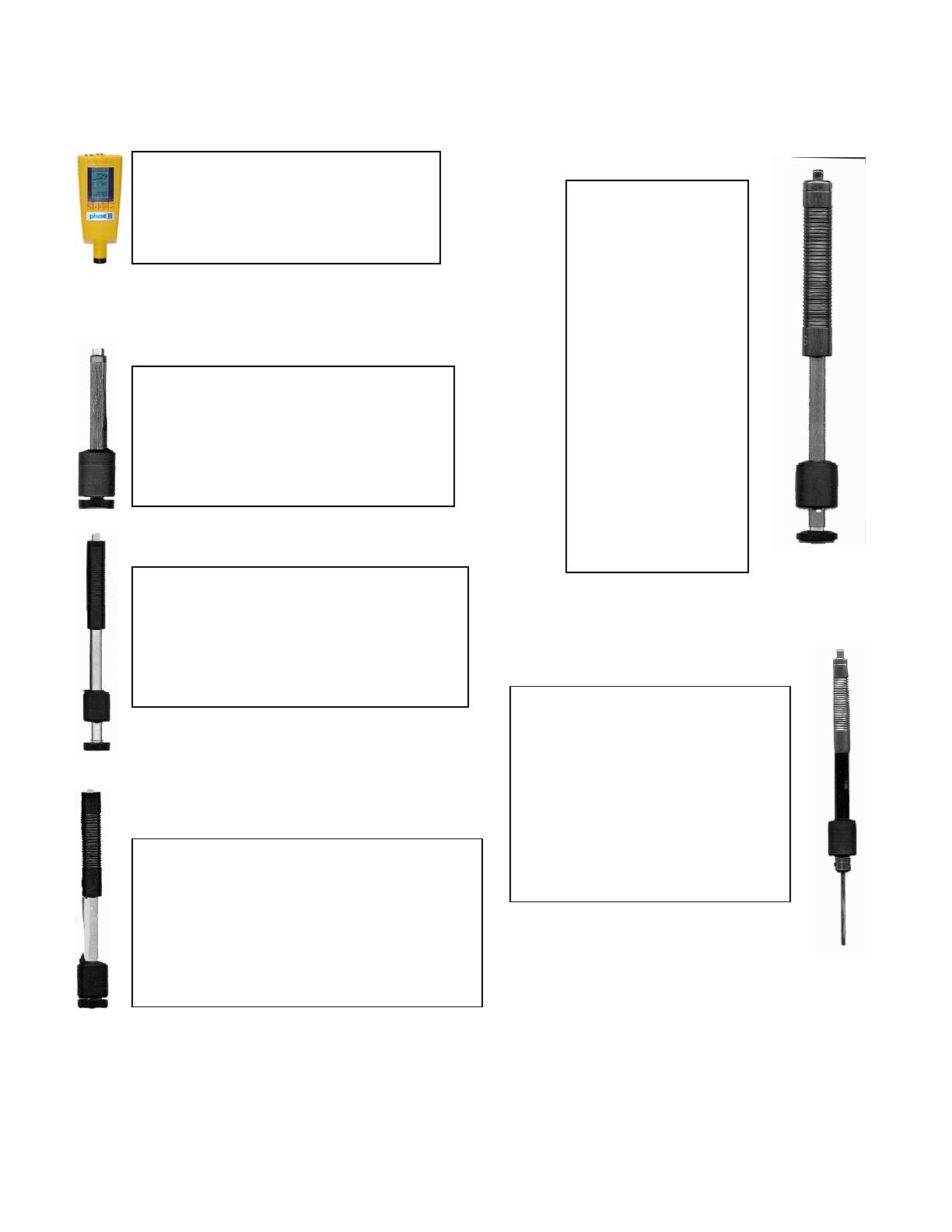
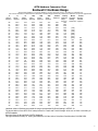
The Phase II PHT-2000 is an advanced hardness tester that provides high accuracy for a wide range of metals. It's suitable for hardness testing in various industries, including petroleum, chemical, machining, and power generation. It offers automatic identification of integrated impact devices, quick data entry, deletion of incorrect test data, display of current test mode and data, and user-selectable display of test data in various hardness values.
The Phase II PHT-2000 is an advanced hardness tester that provides high accuracy for a wide range of metals. It's suitable for hardness testing in various industries, including petroleum, chemical, machining, and power generation. It offers automatic identification of integrated impact devices, quick data entry, deletion of incorrect test data, display of current test mode and data, and user-selectable display of test data in various hardness values.


-
 1
1
-
 2
2
-
 3
3
-
 4
4
-
 5
5
-
 6
6
-
 7
7
-
 8
8
-
 9
9
-
 10
10
-
 11
11
-
 12
12
-
 13
13
-
 14
14
-
 15
15
-
 16
16
-
 17
17


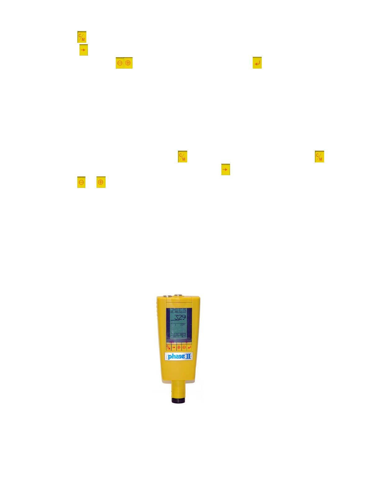
The Phase II PHT-2000 is an advanced hardness tester that provides high accuracy for a wide range of metals. It's suitable for hardness testing in various industries, including petroleum, chemical, machining, and power generation. It offers automatic identification of integrated impact devices, quick data entry, deletion of incorrect test data, display of current test mode and data, and user-selectable display of test data in various hardness values.
Ask a question and I''ll find the answer in the document
Finding information in a document is now easier with AI


