
X4 AND X4M INSTALLATION
AND
OPERATION MANUAL

Table of Contents
General Information............................................................................................................................2
Capacities & Specifications.................................................................................................................2
Acceptance Procedures......................................................................................................................2
Installation........................................................................................................................................2-4
Gas Piping.......................................................................................................................................4-6
Wiring.................................................................................................................................................7
Start Up.........................................................................................................................................7-11
Combustion Arrangement Requirements.....................................................................................11-12
Service/Maintenance Suggestions...............................................................................................12-13
Burner Parts List..........................................................................................................................13-14
Sequence of Operation for X4M Burners..........................................................................................16
X4M Wiring Diagram.........................................................................................................................17
X4M General Arrangement Drawing.................................................................................................17
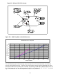
X4M Actuator....................................................................................................................................18
X4M Firing Rate vs. Manifold Pressure.............................................................................................18
-A-

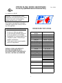
POWER FLAME MODEL X4 BURNERS Rev. 10/04
For use by Qualified Service Personnel Only
U.S. Patent No. 6,508,645
WARNING: If the information in these
instructions is not followed exactly, a fire or
explosion may result causing property
damage, personal injury, or death.
Do not store or use gasoline or any other
flammable liquids in the vicinity of this or
any other appliance.
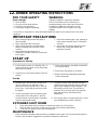
WHAT TO DO IF YOU SMELL GAS
BURNER SPECIFICATIONS
1. Do not try to light any appliance.
2. Do not touch any electrical switch; do
Input Capacity
BTU/Hr
not use any phone in your building.
X4-400150,000 – 400,000
3. Immediately call your gas supplier from
X4-700200,000 – 725,000
a neighbor’s phone. Follow the gas
X4M-400150,000 – 400,000
supplier’s instructions.
X4M-70090,000 – 725,000
4. If you cannot reach your gas supplier,
Fuel Type
Natural or LP Gas
call the fire department.
Blast Tube Length
9”, 12”
Inlet Gas Pressure
X4-4005.0 – 14” w.c.
X4M-4005.5 – 14” w.c.
INSTALLATION AND SERVICE
X4-7005.0 – 14” w.c.
MUST BE PERFORMED BY A
X4M-7005.5 – 14” w.c.
QUALIFIED INSTALLER, SERVICE
Voltage
120V, 60 Hz
AGENCY, OR THE GAS SUPPLIER
Amp Rating
5.0 Amp
Motor
¼ Hp, 3450 RPM
Transformer
40VA, 24 VAC
1


Rev. 10/04
1. GENERAL INFORMATION
The X4 burner is a new generation of gas power burners designed to fire natural gas and propane against
a positive furnace pressure.
The burner is a self-contained unit comprised of a blower assembly, firing head, ignition system,
combination gas valve, flame safeguard and control panel. It only requires connection of 115V electrical
supply, minor gas train piping, connection to gas service, and operating controls.
All Power Flame burners are operationally fire tested at the factory.
2. CAPACITIES & SPECIFICATIONS
Burner NumberX4-400X4-700X4M-400X4M-700
Natural/LP Gas Flow x 1,000 BTU/HR150-400200-725150-40090-725
Gas Train Size3/4”1”3/4”1”
Blower Wheel Size6-1/4” x 2-3/4”7” x 3”6-1/4” x 3-3/4”7” x 3”
Blower Motor HP1/41/41/41/4
Voltage120/60 hz120/60 hz120/60 hz120/60 hz
Maximum Inlet Pressure to Main Shut-
off Cock Inches W.C.
14.014.014.014.0
3.ACCEPTANCE PROCEDURE
Open the box and carefully remove the top cardboard packaging. Lift the burner from the box and ensure
all shipped loose items are removed before discarding the box. Check all parts received against your
computer generated Bill of Material that is enclosed in the owner’s information envelope.
Warranty
The Owners Information envelope packed with the burner contains a Warranty Registration Card. The
Warranty Registration Card is also a request form for a Spare Parts List. An on-hand supply of spare
parts is highly recommended in case of emergency shutdown. We request that you complete and return
the card to Power Flame in the enclosed self-addressed envelope as soon as possible.
4.INSTALLATION
Prior to Installation,please review the MART Operator's Manuel for recommend setting
and flue requirements. Additional charts, drawings and
diagrams shipped with the burner are provided in this manual.
Installation must be in accordance with all local and national codes including CAN1-B149.1 or B149.2 and
Canadian electrical codes for Canadian installations.
2

4.1If the burner is to be mounted in an existing boiler or furnace, ensure that all fireside surfaces are clean
and in good condition. All doors, cleanouts, cracks or other openings allowing excess air into the
combustion chamber should be tightly sealed, whether the burner is to be fired under positive or negative
combustion chamber conditions.
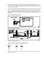
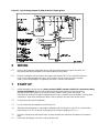
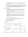
4.2The burner can be mounted through a heat exchanger end wall or in the base of the boiler – see Figures
1 and 2. The opening for the burner blast tube should not be less than 4 ¼ inches in diameter to allow
easy removal of the burner. The gap between the burner opening and the blast tube should be sealed
with non-asbestos, high temperature rope or Ka-O-Wool. Where a new or replacement combustion
chamber lining is to be used the chamber is to be built using 2300 degree F insulating firebrick or ceramic
fiber blanket.
Figure 1 Mounting in Heat Exchanger
Figure 2 Mounting in Boiler Base
4.3 COMBUSTION CHAMBER SIZING
Table 1 Combustion Chamber Recommended Dimensions
Gas InputWidthLength
MBTU/HRInches Inches
250 13 17
450 15 20
600 16 23
700 17 25
850 18 26
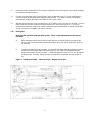
4.4 Whichever method of mounting is chosen, the burner blast tube must be recessed into the front wall
surface from 0” to 1/2”.
3

NOTE: Serious Damage To The Burner May Result If The Blast
Tube Is Extended Into The Combustion Chamber.
4.5 Secure the burner to the heat exchanger or boiler, using the burner-mounting flange. The burner-
mounting flange must be secured to the blast tube at the selected location for proper insertion
into the end or front wall of the fired unit. A tight seal between the mounting flange and the front
plate should be accomplished using the factory-furnished gasket or a ceramic or other non-
asbestos fiber rope.
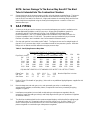
5 GAS PIPING
5.1Contact you local gas service company to ensure that adequate gas service is available and to
review applicable installation codes for your area. All gas piping installations must be in
accordance with NFPA 54, National Fuel Gas Code, Definitions and General Field
Recommendations, CGA 3.0, Canadian Natural Gas Installation Code CAN/CGA B149.1 or
Propane Installation Code, CGA B 149.2. This product must be installed only by a Licensed
Plumber or Gasfitter, when installed in the Commonwealth of Massachusetts.
5.2Size the main gas line in accordance with Table 2. The figures shown are for straight lengths of
pipe at 0.2” w.c. pressure drop, which is considered normal for low-pressure systems. Note that
fittings such as elbows and tees will add to the pipe pressure drop.
Table 2 - Gas Piping Pressure Drop Data
EQUIVALENT LENGTH OF STRAIGHT PIPE IN FEET
203040506080100150200
Pipe Size In InchesCFH GAS WITH .2” PRESSURE DROP
3/4”152120105 93 84 73 66 5445
1”30025021019018015013511075
1-1/4”520425360325300260230190165
1-1/2”800690560500480410370300260
2”17001400120011001000850750600540
2-1/2”30002500210019001800155013751100950
EQUIVALENT LENGTHS OF STANDARD PIPE IN FEET FOR LISTED FITTINGS
Fitting Type3/411-1/2 1-1/222-1/2Nominal Pipe Size In Inches
Std. Tee2.45.57.59.012.013.5
Std. Elbow4.42.73.74.55.56.1
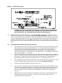
5.3Refer to Figure 3 for details of gas piping. (Also refer to any additional piping diagrams supplied for this
specific unit.)
5.4Mount leakage test and main gas cocks, main automatic gas valve or combination gas
valve/pressure regulator, and auxiliary valves (if required and not factory mounted) per piping
diagram or Figure 3.
5.5Install pressure regulator (not used with combination gas valve/pressure regulator) directly
upstream of main automatic gas valve(s) and fit drip leg and main gas cock upstream of regulator
or automatic valve(s).
5.6 The pilot line should be piped into the upstream tapped nipple to minimize pilot line piping length.
An optional location is in a tapping located on the main shut-off cock. Refer to Figure 3. For
ease of servicing we recommend the use of a union immediately upstream of the main gas
pressure regulator or combination gas valve/pressure regulator.
4

5.7 Install vent lines from main gas regulator (if used) and diaphragm gas valve where applicable.
Vent lines should be run to the outside of the building, terminating clear of windows or fresh air
intakes. Outside termination of vent should have a screen to prevent insects from building nests
in vent pipe. The vent should terminate in a manner, which will preclude the possibility of water,
dirt or other foreign matter from entering the line.
Figure 3 UL Gas Piping Train (X4) – See Figure 11B, page 17, for X4M
5.8Test gas lines for leaks using a soap solution. Your local gas service company may wish to execute or
witness this test. CAUTION – gas pressure above 14” w.c. may damage the standard diaphragm gas
shut-off valve. Do not exceed this value when pressure testing lines unless you cap off line upstream of
main gas cock and pilot take-off.
5.9 Check that side orifice size is correct according to burner specification sheet (See Figure 4). To gain
access to orifice, remove Plug A and withdraw spring and orifice. When reinserting or replacing the
orifice, ensure that it seats properly inside the tee and reinstall plug.
5

Figure 4 Location of Side Orifice
Figure 5 Typical Wiring Diagram for S8680J with Proved Pilot Ignition
6

Figure 5A Typical Wiring Diagram for S89F with Direct Spark Ignition
6 WIRING
6.1 Refer to wiring diagram shipped with burner and typical wiring diagrams Figures 5 and 5A. The
two power leads (black and white) are located inside the burner panel.
6.2Electrical installation must be made in accordance with the NEC NFPA 70 or Canadian Electrical
Code, Part 1 and applicable local codes. If this burner is part of a boiler or furnace package
system, check wiring diagram as supplied by the boiler or furnace manufacturer.
7START UP
7.1Before attempting a burner start up,
please review the MART Operator's Manuel for recommend setting
and flue requirements. Also this manual will provide information about the exact sequence of
operation and all other details on the specific Primary Safety Control System being used. This
information will be found in bulletins supplied with the burner, as well as technical bulletins covering other
components. All of these materials should be used as reference in burner start up and service.
7.2Check boiler water level (if applicable).
7.3Lay out combustion test equipment (see Section 8.3).
7.4Attach gas pressure gauge or manometer to upstream side of main gas cock (0-35” w.c.) and to orifice
pressure tap (0-10” w.c.) as well as to pilot gas pressure test tee tapping (0-10” w.c.).
7.5 Check the voltage at the disconnect switch to make certain that it matches that indicated on the burner
label.
7.6Ensure that all dampers in the flue or stack are fully open.
7

7.7Install stack thermometer and Flue Gas Analyzer sample line into breeching and connect the draft gauge
to combustion chamber test point.
7.8Connect a microammeter to the Primary Safety Control as directed in the PSG control manufacturer’s
instruction bulletin to determine flame detection system values. The meter is normally connected in
series with the (SENSE) terminal on the S8600 or S89F series control.
7.9 With the main and leak test cocks and pilot cock in OFF position, turn on the gas cock at meter. Check to
make certain that pressure upstream of main and pilot cocks does not exceed 14” w.c. (1/2 PSIG) –
unless special valve train components suitably rated have been furnished (Refer to Burner Specification
Sheet). If pressure is acceptable, proceed to next step.
7.10 Pilot Ignition
Next check the operation of the gas pilot system. This is a very important part of the start up
procedure.
A. Before attempting burner start up make certain that you are familiar with the operation of the
Primary Safety Control and other components being used on this specific application. Refer to
Fig. 6 and 6A.
B. To prepare the pilot for proper operation, it is essential that appropriate adjustments be made to
the burner air inlet damper and the pilot gas pressure. See Table 3 for the approximate air
damper setting at the various firing rates. Typical pilot test pressures are 3” to 4” w.c. for natural
and propane gas. Normally, lower pressures are required for air damper openings of 50% or
less.
Figure 6 Pilot/Gun Assembly – Flame Rod Type – Natural Gas/LP Gas
8

Figure 6A Detail Pilot Assembly
C. Frequently the cause for pilot problems relates to gas pressures that are too high and/or
air dampers that are closed too far. Both conditions can cause a fuel rich mixture in the
pilot chamber which can substantially delay or totally prevent pilot ignition.
7.11With the leak gas cock closed and pilot gas cock open (if provided); turn the burner switch ON. The
blower motor will purge the heat exchanger of any accumulated combustibles. At the end of the purge
cycle, the pilot solenoid valve will energize and spark will be initiated. The pilot will attempt to light for 15
seconds. Adjust the pilot pressure at this time. If the pilot fails to light, power must be removed from the
control for 60 seconds to allow it to reset. Note: If the leak test cock is not provided, remove the main
gas valve wire (MV) from the control to prevent the main valve from energizing during the pilot adjustment
period.
7.12Pilot Adjustment and Main Flame Light Off Procedure
A. Set the air flow (see Table 3) and pilot gas pressure in order to provide instant pilot ignition, good
flame stability and a strong/steady signal reading. This can be accomplished as follows: Start
with the pilot pressure at the minimum adjustment on the regulator. When the pilot valve
energizes begin increasing the pilot pressure. Note the pressure where a signal is obtained or
the main valve energizes. This will be the minimum pilot pressure. Acceptable pilot and/or main
flame current reading is 1 – 5 microamp.
B. Raise the pilot gas pressure to the point where the signal and/or main valve drops out noting this
pressure. Reduce the pressure slightly and recycle the burner for an attempt to relight the pilot at
this pressure. If relight occurs this is the upper limit of the pilot pressure. Now set the pilot
pressure between the minimum and maximum pressure. This range is typically 1” w.c..
C. After attaining the proper pilot flame signal values, cycle the pilot off and on several times in order
to ensure reliability (with the gas leak test cock still closed). Turn Burner Switch Off.
D. Having established pilot reliability, open gas leak test cock.
E. After burner has completed pre-purge and established a good pilot flame signal reading, the main
automatic fuel valve will be energized. The main flame should light immediately. If light off does
not occur, it is possible that air will need to be purged from the main gas line. Adjust main gas
pressure regulator (if used) or combination valve regulator to obtain the desired firing rate
pressure.
F. Adjust burner as necessary to provide smooth ignition of main flame. If pilot flame signal drops
significantly when main fuel valve opens, increase pilot gas pressure slightly to obtain a
reasonably stable flame signal value.
9

G. Select and install the main orifice that corresponds to the desired firing rate. Make certain that
the airflow setting provides the correct CO
2
or O
2
levels and other combustion values at the
proper firing input rates.
See Section 8 and Table 3 for firing rate information. Generally accepted values for natural gas
are 8½ to 10% CO
2
or 5½ to 3% O
2
. Equivalent CO
2
readings on propane gas are 10 to 11½%
CO
2
or 5½ to 3½% O
2
. It is important that the CO (carbon monoxide) level is checked and held at
0% or minimum (typically under 100ppm or .01%). Check with local utility and any other
authorities having jurisdiction before making final burner adjustments.
7.13 Direct Spark Ignition
A. Before attempting burner start up make certain that you are familiar with the operation of
the Primary Safety Control and other components being used on this specific application.
Refer to Figure 6b to verify the correct position of the ignition electrode placement since
shipment may have altered the placement.
B. Set the burner’s combustion air inlet damper to the approximate setting as shown in this
manual for the desired firing rate. Also, verify that the correct main orifice is installed in
the main orifice tee.
C. Open the main manual gas valve and turn the combination gas valve to ON. Turn the
burner power on. The blower motor will purge the heat exchanger of any accumulated
combustibles. At the end of the purge cycle, typically 35 seconds, the combination valve
will be energized and a spark will be initiated. The trial for ignition will be approximately
three seconds.
D. Complete setup in accordance with item (G) above.
E. If ignition failure occurs the main power must be switched off for at least one minute to
allow the control to reset. Refer to the Service/Maintenance section for further
information on Direct Spark Ignition.
Figure 6B Detail Direct Spark Gun Assembly
Conduct all applicable test procedures shown in control manufacturer’s bulletins included with burners. Set and
check operation of low and high gas pressure switches (if applicable), all burner and heat exchanger controls, and
10

Rev. 9/05
operating devices. Check blower airflow switch by first closing main gas cock and disconnecting motor
lead wire. A properly adjusted air switch should open within 3 to 4 seconds when the power is removed
from the motor.
7.15Clean up area around the burner and instruct owner and/or operator.
7.16 Post Operating Instructions card (inside back cover) close to the burner in clearly visible position.
8.COMBUSTION ARRANGEMENT REQUIREMENTS
8.1The X4 burner has been designed to fire with high combustion efficiency into combustion chambers with
positive, balanced or negative pressures using natural or LP gas only.
8.2 In order to fire efficiently, the burner requires an adequate supply of combustion air. Ventilation to any
enclosed area should be provided on the basis of ½ square inch of opening for each 1000 BTU/HR input.
This excludes the requirement for any other fired equipment in the area. The enclosed area should not
become excessively hot and under no circumstances should be under a negative pressure.
The burner should be initially set up and serviced at regular intervals (preferably at the beginning of and
mid way through high use periods) by a trained serviceman using the proper test instruments. Failure to
maintain the correct burner settings may result in inefficient gas consumption, premature wear of burner
components or explosion hazard.
8.3 Approximate gas flows and pressures are shown in Table 3 for natural gas and LP gas. Actual firing
rates should be verified by clocking the gas meter and applying the appropriate correction factor.
Table 3
Natural/LP Gas Orifice Pressure Settings/Flow Rate. NOTE: Pressure taken at Combination Valve Pressure
Tap Upstream of Orifice.
X4-400
MainMBH Natural GasMBH LP GasApprox. Damper Position
Orifice1000 BTU/CF2500 BTU/CF
Diameter/I.D.#2"3"4"2"3"4"MBHIndicator #
.203 11331801981501
.234 21581962272002
.265 31501832102132502873003
.281 41752152482192642924004
.343 5200245280298351389
.406 6225274316370431Note: Pilot pressure is different
.468 7275338390410at each damper position and
.500 8295360415must be set at each position.
None400
X4-700
MainMBH Natural GasMBH LP GasApprox. Damper Position
1000 BTU/CF2500 BTU/CFOrifice
Diameter/I.D.#
2"3"4"2"3"4"MBHIndicator #
.203 11742012001
.234 21621982393001 3/4
.265 31201481711942272724002
.281 41311631892012502855003
.343 51862302692733353876004
.406 62463023943834705417006
.468 73063724334725786677259
.500 8326394454497609725Note: Pilot pressure is different
None451563652At each damper position and
725 @4.8"Must be set at each position.
11

8.4The correct test instruments are:
a.O
2
analyzer (electronic or Fyrite absorption system)
b.CO indicator (Monoxor or similar)
c.Stack thermometer
d.Draft gauge or inclined manometer
e.U-tube manometer or calibrated 0-10” and 0-35” w.c. pressure gauge
f.Combination volt/ammeter
g.D.C. Micro-Ammeter
9.SERVICE/MAINTENANCE SUGGESTIONS
9.1 Burner Fails to start:
1.Bad fuse or switch open on in-coming power source, or motor overload out.
2.Control circuit has an open control such as operating, limit or low water cut-off.
3. Push the reset button on the motor or open the power circuit to the primary safety control.
4. Loose or faulty wiring. Tighten all terminal screws. Check wiring, against wiring diagram
furnished with burner.
9.2Burner Motor Runs, but Pilot Does Not Light
1. Be sure gas is turned on at meter and pilot cock is open.
2. Place hand on pilot valve to “feel” it open. Check gauge at tee in pilot line for gas pressure and
prompt opening of pilot valve.
3. Check visually or by sound for spark arcing.
4. Refer to section 7.10 on pilot checking procedures.
5. Check air switch and be sure its circuit closes during start.
9.3Burner Motor Runs, Pilot Lights, but Main Gas Valve Does Not Open
1. Check flame signal. If signal is low, adjust pilot gas pressure and air settings for improved readings.
2. Check gas valve circuit.
3. Shut-off cock or test cock not open.
4. Defective main valve.
9.4Occasional Lockouts For No Apparent Reason
1. Re-check micoamp readings. If insufficient, check gas pressure and air damper setting. Check
electrode setting. If flame signal is low, flame rod may have to be re-positioned.
2. Check ignition cable and electrode porcelain for damage or breaks, which could cause short.
3. Check for loose or broken wires.
9.5Burner Will Not Start – Even Though Burner Had Never Failed Before Or Had Been running On Normal
Cycling Without Failure.
1. Operating Control circuit open.
2. Defective control or loose wiring.
3. Limit circuit open.
9.6 The burner must be periodically inspected to insure safety and performance. All maintenance must be
performed with the main electrical power off and the main gas shutoff valve off.
1. Inspect blower inlet screen and clean any buildup of lint.
2. Inspect blower wheel blades and clean any buildup of dirt.
3. Inspect ignition electrodes and wiring for any cracks that may cause shorting.
4. Oil the blower motor at the manufacturer’s recommended intervals.
5. Verify that the pilot and or direct spark electrodes are still within specifications (set per drawing 6,6A
and 6B in this manual).
6. Verify the proper operation of the Primary Safety Control, airflow switch, and operating controls.
7. Check safety gas shutoff valves for gas tightness.
12

9.7In the event of extended shutdown, the main power should be turned off and the main manual gas shutoff
valve should be closed.
9.6 EMERGENCY SHUTDOWN: WARNING: Should over-heating occur: (1) shut off the manual gas valve
to the appliance, (2) do not shut off the control switch to the feed water pump or blower.
An additional source of information relative to trouble shooting can be found in the Flame Safeguard
Control Manual supplied with the burner.
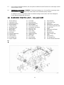
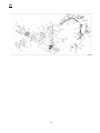
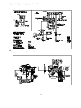
10. BURNER PARTS LIST – X4 and X4M
1. Burner Housing16.Gun Head31.Outer Damper
2. Side Orifice Tee17.Side Orifice tee32.Air Sensing Tube
3. Side Orifice Spring18.Side Orifice Spring33.Orifice Kit
4. Gun Assembly19.Pilot Regulator34.Direct Spark Transformer
5. Flange Gasket20.Pilot Solenoid Valve35.Gas Piping Support Bracket
6. Mounting Flange21.Combination Gas Valve36.Damper Axle
7. Blower Wheel22.Main Gas Cock37.Relay
8. Motor Plate23.Pilot Gas Cock38.5/16” Ball Joint Swivel
9. Blower Motor24.Pilot Tubing39.Mod Motor
10. Air Switch25.Pilot Assembly40.Butterfly Valve
11. 24 Volt Transformer26.Ignition Electrode41.5/16” Linkage Rod
12. Panel & Door27.Flame Rod42.Light
13. Flame Monitor28.Back Plate43.Axle Bushing
14. Grounding Lug29.Inner Damper44.1/2” Damper Arm
15. Nipple Tapped30.Middle Damper45.Pie DPR Retainer Washers
X4
13

X4M
14

15

11. SEQUENCE OF OPERATION FOR X4M BURNER
11.1 Refer to typical wiring diagram for X4M burner (Figure 11A). Upon a call for heat, the blower motor
starts, closing the combustion air switch. Power is supplied to the 24-vac transformer. Initially power
to the actuator is held out through one set of normally open contacts on the 24-vac relay.
11.2 Since power is not supplied to the actuator it will spring return clockwise to the open damper position
if not already there. When the actuator reaches the full clockwise position (full open damper) the
internal auxiliary end switch closes (S1 to S3).
11.3 24-vac power will be supplied through the S1 – S3 contacts and the combustion air switch to the
S8680 control.
11.4 The control will begin its pre-purge time period of approximately 30 seconds.
11.5 At the end of the pre-purge period, a trial for ignition will be attempted. On pilot ignited burners the
pilot pressure would be set here to achieve the best pilot performance. Refer to Pilot Adjustment
Procedure earlier in section 7.10 of this manual.
11.6 When the main gas valve is energized, after a proven pilot or during direct spark ignition on DSI
burners the 24-vac relay will also be energized.
11.7 One set of normally open relay contacts close which interlocks the high fire auxiliary end switch.
Another set of relay contacts closes and completes the modulation circuit.
11.8 Modulation of the burner is now accomplished by the control signal. Depending on the setting of the
Direction Control Switch located on the actuator (Figure 11C), a low or high input signal can drive the
actuator clockwise or counterclockwise (low fire or high fire).
11.9 An adjustable stop located on the actuator (Figure 11C), can be used to limit the high fire or low fire
position. If the high fire damper position is changed due to a lower than maximum firing rate, the pilot
should be rechecked at this new damper position.
16

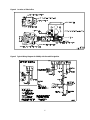
Figure 11A - Typical Wiring Diagram For X4M
Figure 11B – General Arrangement Diagram for X4M
17
Page is loading ...
Page is loading ...
-
 1
1
-
 2
2
-
 3
3
-
 4
4
-
 5
5
-
 6
6
-
 7
7
-
 8
8
-
 9
9
-
 10
10
-
 11
11
-
 12
12
-
 13
13
-
 14
14
-
 15
15
-
 16
16
-
 17
17
-
 18
18
-
 19
19
-
 20
20
-
 21
21
-
 22
22


PF X4M-400 Operating instructions
- Type
- Operating instructions
Ask a question and I''ll find the answer in the document
Finding information in a document is now easier with AI
Other documents
-
BENDIX TCH-007-002 User manual
-
-
Burnham Series C Ratings
-
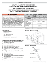 UTICA BOILERS MGB Series II/MGC Series Operation and Installation Manual
-
Precision FPS-62-100 Installation and Operating Instruction
-
Reznor TR User manual
-
Beckett CG10 Gas Burner Owner's manual
-
HP SU-2A User manual
-
Midco 400B-33 Installation guide
-
 Nu-Way MULTIPLEX MP series Installation and Maintenance Manual

