
– 1 –
XL-560,570/C
CONTENTS Page
IMPORTANT SERVICE NOTES (FOR U.S.A. ONLY)...................................................................................................... 2
SPECIFICATIONS ............................................................................................................................................................ 2
NAMES OF PARTS .......................................................................................................................................................... 3
OPERATION MANUAL (FOR XL-560/570) ...................................................................................................................... 5
QUICK GUIDE (FOR XL-560/570).................................................................................................................................... 7
DISASSEMBLY................................................................................................................................................................. 8
REMOVING AND REINSTALLING THE MAIN PARTS.................................................................................................... 9
ADJUSTMENT................................................................................................................................................................ 10
TEST MODE ................................................................................................................................................................... 11
NOTES ON SCHEMATIC DIAGRAM ............................................................................................................................. 15
TYPE OF TRANSISTOR AND LED................................................................................................................................ 15
BLOCK DIAGRAM .......................................................................................................................................................... 16
SCHEMATIC DIAGRAM / WIRING SIDE OF P.W.BOARD............................................................................................ 20
WAVEFORMS OF CD CIRCUIT..................................................................................................................................... 27
TROUBLESHOOTING.................................................................................................................................................... 28
FUNCTION TABLE OF IC .............................................................................................................................................. 34
LCD SEGMENT .............................................................................................................................................................. 42
PARTS GUIDE/EXPLODED VIEW
PACKING OF THE SET (FOR U.S.A. ONLY)
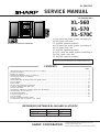
XL-560
XL-570
XL-570C
SERVICE MANUAL
SHARP CORPORATION
No. S6941XL560///
• In the interests of user-safety the set should be restored to its original
condition and only parts identical to those specified should be used.
This document has been published to be used
for after sales service only.
The contents are subject to change without notice.
Illustration: XL-560/570,CP-XL560U/570U
DIFFERENCE BETWEEN XL-560 AND XL-570/570C
CD Lid Panel None Used
Speaker Cord None Used
XL-560
SECTION XL-570/570C
XL-560 desk top audio system consisting of
XL-560 (main unit) and
CP-XL560U (speaker system).
XL-570 desk top audio system consisting of
XL-570 (main unit) and
CP-XL570U (speaker system).
XL-570C desk top audio system consisting of
XL-570C (main unit) and
CP-XL570U (speaker system).

XL-560,570/C
– 2 –
IMPORTANT SERVICE NOTES (FOR U.S.A. ONLY)
SPECIFICATIONS
FOR A COMPLETE DESCRIPTION OF THE OPERATION OF THIS UNIT, PLEASE REFER
TO THE OPERATION MANUAL.
AC SCALE
VTVM
1.5k ohms
10W
0.15µF
TEST PROBE
TO EXPOSED
METAL PARTS
CONNECT TO
KNOWN EARTH
GROUND
Specifications for this model are subject to change without
prior notice.
XL-560/570/C
CP-XL570U
CP-XL560U
BEFORE RETURNING THE AUDIO PRODUCT
(Fire & Shock Hazard)
Before returning the audio product to the user, perform the
following safety checks.
1. Inspect all lead dress to make certain that leads are not
pinched or that hardware is not lodged between the chassis
and other metal parts in the audio product.
2. Inspect all protective devices such as insulating materials,
cabinet, terminal board, adjustment and compartment covers
or shields, mechanical insulators etc.
3. To be sure that no shock hazard exists, check for leakage
current in the following manner.
* Plug the AC line cord directly into a 120 volt AC outlet.
* Using two clip leads, connect a 1.5k ohm, 10 watt resistor
paralleled by a 0.15µF capacitor in series with all exposed
metal cabinet parts and a known earth ground, such as
conduit or electrical ground connected to earth ground.
* Use a VTVM or VOM with 1000 ohm per volt, or higher,
sensitivity to measure the AC voltage drop across the
resistor (See diagram).
* Connect the resistor connection to all exposed metal parts
having a return path to the chassis (antenna, metal cabinet,
screw heads, knobs and control shafts, escutcheon, etc.)
and measure the AC voltage drop across the resistor.
All check must be repeated with the AC line cord plug connection
reversed.
Any reading of 0.3 volt RMS (this corresponds to 0.2 milliamp.
AC.) or more is excessive and indicates a potential shock
hazard which must be corrected before returning the audio
product to the owner.
General
Power source: AC 120 V, 60 Hz
Power consumption: 50 W
Dimensions: Width; 6-5/16" (160 mm)
Height; 9-1/2" (241 mm)
Depth; 11-3/4" (298 mm)
Weight: 7.3 lbs. (3.3 kg)
Amplifier section
Output power: 16 watts minimum RMS per
channel into 4 ohms from
100 Hz to 20 kHz, 10%
total harmonic distortion
Output terminals: Speakers; 4 ohms
Headphones; 16-50 ohms
(recommended; 32 ohms)
CD digital output (optical)
Sub woofer (Audio signal);
500 mV / 47 kohms
Input terminals: Video/Auxiliary (audio sig-
nal); 500 mV/47 kohms
Compact disc player section
Type: Compact disc player
Signal readout: Non-contact, 3-beam semi-
conductor laser pickup
D/A converter: 1-bit D/A converter
Filter: 8-times oversampling digital
filter
Frequency
response: 20 - 20,000 Hz
Wow and flutter: Unmeasurable (less than
0.001% W. peak)
Tuner section
Frequency range: FM; 87.5-108 MHz
AM; 530-1,720 kHz
Cassette deck section
Frequency
response: 50 - 14,000 Hz
(Normal tape)
Signal/noise ratio: 50 dB
Wow and flutter: 0.25 % (WRMS)
Speaker section
Type: 2-way [4-3/4" (12 cm)
woofer and 1" (2.5 cm)
semi-dome tweeter]
Rated input power: 20 W
Maximum input
power: 40 W
Impedance: 4 ohms
Dimensions: Width; 6-5/16" (160 mm)
Height; 9-1/2" (240 mm)
Depth; 7-7/16" (189 mm)
Weight: 5.5 lbs. (2.5 kg)/each
Type: 2-way [4" (10 cm) woofer
and 5/8" (1.5 cm) tweeter]
Rated input power: 20 W
Maximum input
power: 40 W
Impedance: 4 ohms
Dimensions: Width; 6-5/16" (160 mm)
Height; 9-1/2" (240 mm)
Depth; 7-7/16" (189 mm)
Weight: 4.4 lbs. (2.0 kg)/each

– 3 –
XL-560,570/C
NAMES OF PARTS
XL-560/570/C
Illustration: XL-560/570
■ Rear panel
11. AC Power Input Socket
12. FM 75 ohms Aerial Socket
13. AM Loop Aerial Input Socket
14. Video/Auxiliary (Audio Signal) Input
Sockets
15. Sub Woofer Output Socket
16. Speaker Terminals
1
2
3
6
4
5
■ Front panel
11. Timer Indicator
12. Record Indicator
13. Sleep Indicator
14. (CD) Random Indicator
15. (CD/TUNER) Memory Indicator
16. FM Stereo Mode Indicator
17. (CD) Play Indicator
18. (CD) Repeat Indicator
19. FM Stereo Indicator
10. CD Compartment
11. Power Button
12. Volume/Jog Dial Selector Button
13. Record Pause/Beat Cancel Selector Button
14. Clock/Timer/Sleep Button
15. Function Selector Button
16. Remote Control Sensor
17. Band Selector Button
18. Memory/Set Button
19. CD Eject Button
20. Bass/Treble Selector Button
21. (CD) Play/Pause Button
(TAPE) Play Button
22. (CD/TAPE) Stop Button
(TUNER) Clear Button
23. (CD) Cue Button
(TAPE) Fast Forward Button
(TUNER) Tuning Up Button
24. (CD) Review Button
(TAPE) Rewind Button
(TUNER) Tuning Down Button
25. Jog Dial
26. Headphone Socket
27. Cassette Compartment
28. CD Digital Output Socket
123 4 56
7 8 9
10
11
12
13
14
15
16
17
18
19
20
21
22
23
24
25
26 2827

XL-560,570/C
– 4 –
CP-XL570U
XL-560,570/C
1
23
4
1
23
4
Illustration: XL-560/570
CP-XL560U
■ Speaker section
1. Tweeter
2. Woofer
3. Bass Reflex Ducts
4. Speaker Wire
1. Tweeter
2. Woofer
3. Speaker Terminals
4. Bass Reflex Ducts
■ Remote control
1. Remote Control Transmitter LED
●Tuner control section
2. Preset Up/Down Buttons
●CD control section
3. Clear Button
4. Random/Repeat Button
5. Memory Button
6. Stop Button
7. Play/Pause Button
8. Track Down/Review Button
●Tape control section
10. Record Pause/Beat Cancel Selector
Button
11. Rewind Button
12. Stop Button
13. Play Button
14. Fast Forward Button
●Common section
15. Sleep Button
16. Bass Up/Down Buttons
17. Function Selector Buttons
18. Power Button
19. Timer Button
20. Clock Button
21. Treble Up/Down Buttons
22. Volume Up/Down Buttons
9. Track Up/Cue Button
1
2
3
4
5
6
7
8
9
10
11
12
13
14
15
16
17
18
19
20
21
22

– 5 –
XL-560,570/C
OPERATION MANUAL (FOR XL-560/570)
PREPARATION FOR USE
Unplug the AC power cord from the AC out-
let before connecting or disconnecting any
component.
Caution for XL-570:
Before connecting the speakers to the
unit, connect the speaker wires to the
speakers first. Then, connect the
speaker wire to the terminals on the unit.
Connect the speakers to the main unit,
and then use the system. If any of the
speakers are not connected, the main
unit or the speakers may malfunction or
may be damaged.
Speaker connection
Connect each speaker wire to the SPEAKER termi-
nals as shown.
Use speakers with an impedance of 4 ohms or more.
Use of speakers with an impedance less than 4
ohms may damage your unit.
Connect the wire with the white line to the minus
(−) terminal and the plain wire to the plus (+) ter-
minal.
Notes:
Do not mix the right channel and left channel wir-
ing when connecting the speakers to the unit.
Do not let the bare speaker wires touch each other
as this may damage the amplifier and/or speakers.
Do not allow any objects to fall into or to be placed
in the bass reflex ducts.
Caution:
The speakers included with the unit should only
be used with the XL-570 or XL-560. Do not use
them with other models. Do not connect the XL-
570's or XL-560's speaker terminals to any speak-
ers other than those included with the unit.
RATED SPEAKER IMPEDANCE:
4 OHMS MIN.
SPEAKERS
LEFT
RIGHT
2
13
Right speaker Left speaker
Black
White
line
Black
In the case of XL-560
In the case of XL-570
RATED SPEAKER IMPEDANCE:
4 OHMS MIN.
SPEAKERS
LEFT
RIGHT
2
13
Right speaker Left speaker
White
line
Black
Black
Black White
line
TV,PC monitor location:
The speakers are magetically shielded. The speak-
ers may be used by the sides of the TV or PC Mon-
itor.
Depending on the particular location of a TV, or
PC monitor, color variations may appear on the
TV, or PC monitor screen. If this occurs, move the
systems speakers away from the TV/PC monitor
and turn it off. After 15 - 30 minutes, turn on the
TV/PC monitor again.
The TV, or PC monitor's own demagnetizing func-
tion should eliminate the variations.
If the color variations still appear, move the system
further away from the TV, or PC monitor.
If any kind of magnet or an electromagnet is
placed too close to the TV/PC monitor and the
system, irregular colors may appear on the TV or
PC monitor screen.
(Continued)
SUB
WOOFER
OUT
Speaker with a
built-in amplifier
Sub woofer
When a commercially available speaker with a
built-in amplifier is connected to this unit, you can
enjoy sound with emphasized bass.
Connect an RCA cord from a commercially
available speaker with a built-in amplifier to the
SUB WOOFER OUT jack.
Remote control
Notes concerning use:
Replace the batteries if the operating distance is
reduced or if the operation becomes erratic.
Periodically clean the transmitter LED on the re-
mote control and the sensor on the main unit with
a soft cloth.
Exposing the sensor on the main unit to strong
light may interfere with operation. Change the
lighting or the direction of the unit.
Keep the remote control away from moisture, ex-
cessive heat, shock, and vibrations.
15
15
8" - 20'
(0.2 m - 6 m)
(Continued)
RESETTING THE MICROCOMPUTER
1
Press the POWER button to enter the stand-by
mode.
2
Unplug the AC power cord from the AC INPUT
jack on this unit.
3
While pressing down the MEMORY/SET button
and the BASS/TREBLE button, plug the AC
power cord into the AC INPUT jack on this unit.
Caution:
The operation explained above will erase all data
stored in memory, such as clock and timer settings,
and tuner and CD presets.
1
3
3
2,3
Reset the microcomputer under the following con-
ditions:
To erase all of the stored memory contents (clock
and timer settings, and tuner and CD presets).
If the display is not correct.
If the operation is not correct.

XL-560,570/C
– 6 –
SETTING THE CLOCK
In this example, the clock is set for the 12-hour
(AM 12:00) system.
3
Turn the jog dial to select the time display
mode.
"AM 12:00" →The 12-hour display will appear.
(AM 12:00 - PM 11:59)
"0:00" →The 24-hour display will appear.
(0:00 - 23:59)
Note that this can only be set when the unit
is first installed or it has been reset.
4
Press the MEMORY/SET button.
5
Adjust the hour by turning the jog dial.
When the jog dial is turned one click clockwise,
the time will increase by 1 hour. When it is
turned one click counterclockwise, the time will
decrease by 1 hour.
Keep turning the jog dial to change the time
continuously.
When the 12-hour display is selected, "AM" will
change automatically to "PM".
6
Press the MEMORY/SET button.
7
Adjust the minutes by turning the jog dial.
When the jog dial is turned one click clockwise,
the time will increase by 1 minute. When it is
turned one click counterclockwise, the time will
decrease by 1 minute.
Keep turning the jog dial to change the time
continuously.
The hour setting will not advance even if min-
utes advance from "59" to "00".
8
Press the MEMORY/SET button.
The clock starts operating from "0" seconds.
(Seconds are not displayed.)
Note:
In the event of a power failure or when the AC
power cord is disconnected, the clock display
will go out.
When the AC power supply is restored, the
clock display will flash on and off to indicate
the time when the power failure occurred or
when the AC power cord was disconnected.
If this happens, follow the procedure below to
change the clock time.
To change the clock time:
Perform steps 1, 2 and 5 - 8 above.
To change the time display mode:
Perform steps 1 - 3 in the section "RESET-
TING THE MICROCOMPUTER".
Perform steps 1 - 8 above.
Jog dial
(Main unit operation)
CLOCK/TIMER/
SLEEP
MEMORY/
SET
AM 12:00 0:00
2
3
4
5
6
7
8
1
Press the CLOCK/TIMER/SLEEP button to
enter the time check mode.
2
Within 3 seconds, press the MEMORY/SET
button.
1
2
RIGHT
USING EXTERNAL UNITS
CD digital output (optical)
The CD digital signal from this unit can be re-
corded by other DAT or MiniDisc recorders.
1
Remove the DIGITAL OUT jack cover.
2
Use a commercially available digital cable to con-
nect the unit to the OPTICAL IN jack of a
MiniDisc recorder or a DAT.
3
Put the external unit in the recording mode.
4
Play a CD on this unit.
Commercially available digital cable
Before plugging in or unplugging the headphones,
make sure the volume level is reduced.
Be sure your headphones have a 1/8" (3.5 mm) di-
ameter plug and are between 16 ohms and 50 ohms
impedance. The recommended impedance is 32
ohms.
When headphones are connected, the speakers are
disconnected automatically. Adjust the VOLUME con-
trol for desired volume.
Headphones
Note:
Only CD signals can be output from this unit to
other DAT or MiniDisc recorders.
RIGHT
LEFT
VIDEO/AUX
To the output
jack
To the line
output jack
LEFT
A cable [a 1/8" (3.5 mm) ste-
reo mini-plug to pin-plugs]
RCA cord
RCA cord
LEFT
RIGHT
RIGHT LEFT
To the line output jack
Connect each plug completely. If the units are not
connected correctly, it may not be possible to re-
cord or playback properly.
Before connecting external units, turn the power
to this unit and external units off.
VIDEO/AUX (Audio signal) input
To listen to or record signals from external
sources (personal computer, VCR, etc.) through
this unit:
1
Use a separately available RCA cord or a sep-
arately available cable [a 1/8" (3.5 mm) stereo
mini plug to pin plugs] to connect the desired
external unit to the VIDEO/AUX jacks.
(red → right channel, white → left channel)
Notes:
When your computer is not equipped with an
audio output terminal, a PC sound board is
needed.
When using video equipment (Laser Disc player,
VCR), be sure to connect the audio output to this
unit and the video output to a television.
2
Press the POWER button to turn the power on.
3
Press the FUNCTION button until "AUX" appears
in the display.
4
Operate the external unit.
5
To record the sound from the external unit, per-
form steps 2 - 4 of the "Recording from the built-
in radio".
Notes:
To prevent hum interference, do not place this unit
near television receivers and be careful not to turn the
computer volume up too high.
When turning the computer on or off, noise may be
heard, depending on the model.
Before turning your computer on or off, put the
POWER button on this unit in the stand-by mode, or
decrease the volume.
When an external unit with a built-in microphone or a
mixing microphone function is connected to this unit,
howling may occur due to feedback. Decrease the
volume of this unit or the microphone volume of the
external unit, or move the microphone away from the
speakers.

– 7 –
XL-560,570/C
QUICK GUIDE (FOR XL-560/570)
RATED SPEAKER IMPEDANCE:
4 OHMS MIN.
SPEAKERS
LEFT
RIGHT
2
Preparation for use /
Preparación para su uso
Remote control x 1
Controlador remoto x 1
Speaker connection
Conexión de los altavoces
Antenna connection
Conexión de las antenas
Right speaker
Altavoz derecho
White line
Líneas
blancas
Black
Negro
DESK TOP AUDIO SYSTEM
Quick Guide/Guía rápida XL-570/XL-560
1
Check the supplied accessories /
Compruebe los accesorios suministrados
AC power cord x 1
Cable de alimentación
de CA x 1
FM antenna x 1
Antena de FM x 1
AM loop antenna x 1
Antena de cuadro de
AM x 1
Speaker wire x 2
(Only supplied with the XL-570)
Cable del altavoz delantero x 2
(Sólo suministrado con el XL-570)
ANTENNA
LOOP
FM
75
OHMS
White
line
Línea
blanca
Left speaker
Altavoz izquierdo
Black
Negro
White
line
Línea
blanca
FM Antenna
Antena de FM
In case of XL-570
En el caso del XL-570
AM Loop Antenna
Antena de cuadro
de AM
AC 120 V, 60 Hz
120 V de CA, 60 Hz
Turning the power on and off
Conexión y desconexión de la
alimentación
Remote control
Controlador remoto
POWER
POWER
2 “AA” batteries
Dos pilas “AA”
Remote Sensor
Sensor remoto
Batteries are not included.
Las pilas no están incluidas.
15
15
8” - 20’ (0.2m - 6m)
0,2m - 6m
Black
Negro
4
Listening to a tape /
Audición de una cinta
5
Listening to the radio /
Audición de la radio
6
Recording from CD /
Grabaciones de un disco CD
7
Sound control /
Control del sonido
To stop playback
Para detener la reproducción
To stop recording
Para detener la
grabación
Volume
Volumen
Bass
Graves
Treble
Agudos
3
Listening to a CD /
Audición de un disco CD
FUNCTION
FUNCTION
FUNCTION
(FM STEREO)
(FM MONO)
(AM)
BAND
TUNING
FUNCTION
REC PAUSE
VOLUME / MULTI JOG
D
O
W
N
P
R
E
S
E
T
U
P
CD
CD
VOLUME / MULTI JOG
D
O
W
N
P
R
E
S
E
T
U
P
CD
CD
VOLUME / MULTI JOG
D
O
W
N
P
R
E
S
E
T
U
P
CD
CD
Load the
disc to be
recorded.
Introduzca
el disco
que va a
grabar.
CD recording
starts.
La grabación de
CD empieza.
The tape
will stop
La cinta se
detendrá.
The CD
will stop.
EI CD se
detendrá.
Open
Abra
Label side up.
Con el lado de la
etiqueta encarada
hacia arriba.
Close
Cierre
To stop playback
Para detener la
reproducción

XL-560,570/C
– 8 –
1 Side Panel 1. Screw .................. (A1) x8 8-1
(Left/Right)
2 Top Cabinet/ 1. Screw .................. (B1) x1 8-1
Switch PWB 2. Socket ................. (B2) x3
(Note) 3. Hook .................... (B3) x2
3 Rear Panel 1. Screw .................. (C1) x3 8-1
2. Screw .................. (C2) x2
4 Power Amp. PWB 1. Screw .................. (D1) x1 8-2
2. Socket ................. (D2) x2
5 Main PWB/ 1. Screw .................. (E1) x2 8-3
Headphones PWB 2. Screw .................. (E2) x3
3. Bracket ................ (E3) x1
4. Socket ................. (E4) x3
6 Display PWB/ 1. Screw .................. (F1) x4 8-3
CD Servo PWB/ 2. Socket ................. (F2) x4
LED PWB 3. Knob .................... (F3) x1
(With Switch PWB) 4. Hook .................... (F4) x6
7 Front Panel 1. Screw .................. (G1) x1 8-3
8 Power PWB 1. Screw .................. (H1) x4 8-3
2. Screw .................. (H2) x1
3. Screw .................. (H3) x2
4. Bracket ................ (H4) x1
9 CD Digital PWB 1. Screw .................. (J1) x1 9-1
2. Cover................... (J2) x1
10 Tape Mechanism 1. Open the cassette holder 9-1
2. Screw .................. (K1) x4
11 CD Mechanism 1. Screw .................. (L1) x3 9-2
DISASSEMBLY
Figure 8-2
Figure 8-3
STEP REMOVAL PROCEDURE FIGURE
Figure 8-1
XL-560,570/C
Note:
After removing the connector for the optical pickup from the
connector, wrap the conductive aluminium foil around the
front end of connector to protect the optical pickup from
electrostatic damage.
Caution on Disassembly
Follow the below-mentioned notes when disassembling
the unit and reassembling it, to keep it safe and ensure
excellent performance:
1. Take cassette tape and compact disc out of the unit.
2. Be sure to remove the power supply plug from the wall
outlet before starting to disassemble the unit.
3. Take off nylon bands or wire holders where they need to
be removed when disassembling the unit. After servicing
the unit, be sure to rearrange the leads where they were
before disassembling.
4. Take sufficient care on static electricity of integrated
circuits and other circuits when servicing.
XL-560,570/C
STEP REMOVAL PROCEDURE FIGURE
1 Speaker 1. Net........................... (A1) x1 9-3
2. Front Panel ............. (A2) x1
3. Screw ...................... (A3) x4
4. Screw ...................... (A4) x2
5. Holder ..................... (A5) x1
CP-XL560U
STEP REMOVAL PROCEDURE FIGURE
1 Speaker 1. Net........................... (A1) x1 9-4
2. Screw ...................... (A2) x4
3. Ring......................... (A3) x1
4. Screw ...................... (A4) x4
CP-XL570U
(D1)x1
ø3x8mm Main PWB
Power
PWB
Power Amp.
PWB
CD Servo
PWB
(D2)x2
(A1)x1
ø3x10mm
(A1)x1
ø3x10mm
(A1)x2
ø3x10mm
(C1)x2
ø3x10mm
(C2)x2
ø3x8mm
(B1)x1
ø3x10mm
Top Cabinet
Side Panel
(Right)
Front
Panel
RearPanel
(C1)x1
ø3x10mm
Side Panel
(Lift)
(B2)x2
(B2)x1
CD Mechanism
CD Motor PWB
Swicth
PWB
Top
Cabinet
(B3)x2
(A1)x4
ø3x10mm
(F1)x4
ø2.5x10mm
(E2)x2
ø3x8mm
CD Servo PWB
Main PWB
Power PWB
Power PWB Main Power Transformer
Sub Power
Transformer
Front Panel
LED PWB
Display PWB
(H1)x4
ø4x6mm
(E2)x1
ø3x8mm
(E1)x1
ø3x10mm
(E3)x1
(F2)x1
(H2)x1
ø3x10mm
(H3)x1
ø3x6mm (G1)x1
ø3x8mm
(H3)x1
ø3x6mm
(F2)x2
(F4)x6
(F3)x1
(E4)x1
(H4)x1
Tape
Mechanism
PWB
(F2)x1
Headphones
PWB
(E4)x2
(E1)x1
ø3x10mm
Sub Power Transformer

– 9 –
XL-560,570/C
How to remove the pickup (See Fig. 9-5)
1. Remove the mechanism cover, paying attention to the
pawls (A1) x 4 pcs.
2. Remove the screws (A2) x 2 pcs., to remove the shaft (A3)
x 1 pc.
3. Remove the stop washer (A4) x 1 pc., to remove the gear
(A5) x 1 pc.
4. Remove the pickup.
Note:
After removing the connector for the optical pickup from the
connector, wrap the conductive aluminium foil around the
front end of connector to protect the optical pickup from
electrostatic damage.
REMOVING AND REINSTALLING THE MAIN PARTS
CD MECHANISM SECTION
Perform steps 1 to 6 and 11 of the disassembly method to
remove the CD mechanism.
Pickup Unit
(A2) x2
ø2.6 x6mm
(A1) x2
CD Mechanism
Shaft
(A3) x1
Gear
(A5) x1
StopWasher
(A4) x1
Mechanism Cover
(A1) x2
CP-XL560U
Figure 9-4
Figure 9-3
CP-XL570U
Figure 9-1
Figure 9-2
Figure 9-5
Tape
Mechanism
Open
(K1)x4
ø2.5x10mm
(J1)x1
ø2.5x10mm
Front Panel
Cassette
Holder
CD Digital
PWB
PWB
Holder
(J2)x1
CD Mechanism
(L1)x3
ø2.5x10mm
PWB Washer x3
Top Cabinet
(A1)x1
(A2)x1 (A5)x1
(A4)x2
ø3x12mm
Woofer
Tweeter
(A3)x4
ø4x20mm
Speaker Box
(A1)x1
(A3)x1
(A4)x4
ø3x12mm
Woofer
Tweeter
(A2)x4
ø4x16mm
Speaker Box

XL-560,570/C
– 10 –
MECHANISM SECTION
• Driving Force Check
Torque Meter Specified Value
Play: TW-2412 Over 80 g
• Torque Check
Torque Meter
Play: TW-2111 30 to 60 g. cm
Fast forward: TW-2231 55 to 140 g.cm
Rewind: TW-2231 55 to 140 g.cm
Specified
Value
Adjusting
Point Instrument
Connection
Test Tape
MTT-111 Motor 3,000 ±Headphone
(M901) 90 Hz terminal
ADJUSTMENT
Specified Value
• Tape Speed
fL: Low-range frequency
fH: High-renge frequency
• AM IF/RF
Signal generator: 400 Hz, 30%, AM modulated
IF 450 kHz 1,720 kHz T351 *1
AM Band — 530 kHz (fL): T306 *2
Coverage 1.1 ± 0.1 V
AM 990 kHz 990 kHz T302 *1
Tracking
Test Stage Frequency Frequency
Display Setting/
Adjusting
Parts
Instrument
Connection
Adjusting
Parts
Display
Figure 10-1 ADJUSTMENT POINT
TUNER SECTION
Frequency
• Setting the Test Mode
Keeping the FF/FWD button and MEMORY/SET button
pressed, turn on POWER. Then, the frequency is initially set
in the memory as shown in Table. Call it with the JOG DIAL
knob to use it for adjustment and check of tuner circuit.
Preset No. FM STEREO Preset No. AM
1 87.5 MHz 6 530 kHz
2 108.0 MHz 7 1,720 kHz
3 98.0 MHz 8 990 kHz
4 90.0 MHz 9 600 kHz
5 106.0 MHz 10 1,400 kHz
• FM Mute Level
Signal generator: 1 kHz, 40 kHz dev., FM modulated
*1. Adjust so that an output signal appears.
Check Point Instrument
Connection
Display
Frequency
87.5 MHz 87.5 MHz 2.2 V ± 0.7 V TP301
108 MHz 108 MHz 7.3 V ± 1.0 V TP301
• Check FM VT
Signal generator: 1 kHz, 40 kHz dev., FM modulated
*1. Input: Antenna, Output: Speaker Terminal
*2. Input: Input is not connected, Output: TP301
98.00 MHz 98.0 MHz VR351*1 Input: SO301
(25 dBµV) Output: Speaker
Terminal
Instrument
Connection
Preset No.
11~25
Preset No. FM MONO
26 106.0 MHz
27 90.0 MHz
28 98.0 MHz
29 108.0 MHz
30 87.5 MHz
BAND
TAPE MECHANISM
M901
Tape
Motor
Variable
resistor
• FM Detection
Signal generator: 10.7 MHz, FM sweep generator
FM IF 10.7 MHz 98.0 MHz T304(Turn Input: Pin 1 of
the core of IC301
T304 fully Output: TP302
counter-
clockwise.
Test
Stage Frequency Frequency
Display Setting/
Adjusting
Parts
Instrument
Connection
Figure 10-2 ADJUSTMENT POINTS
IC303
IC302
CF352
R336
T306
VR351
T302
CNP602
T304
L303
IC301
L302
BF301
T351
1
9
MAIN PWB
AM
ANTENNA
SOCKET
FM Mute
Level
AM IF
TP301
CNP301
AM
Tracking
AM Band
Coverage fL
TP302
FM Band
Coverage fL
FM RF
FM IF
FM
ANTENNA
SOCKET
SO301
• FM RF
Signal generator: 1 kHz, 75 kHz dev., FM modulated
FM Band — 87.5 MHz (fL): L303 *1
Coverage 3.4 ± 0.1 V
FM RF 98.00 MHz 98.0 MHz L302 *2
(10~30 dB)
Test Stage Frequency Frequency
Display Setting/
Adjusting
Parts
Instrument
Connection
*1. Input: Antenna, Output: TP301
*2. Input: Antenna, Output: Speaker Terminal

– 11 –
XL-560,570/C
2. CD Test Mode (TEST 1)
In the CD test mode the operation of each step is enabled even when the LID-SW is off. However, if focus cannot be set in step
3 or any error processing is started, it is impossible to proceed to the next step. When the error processing is started, operations
other than termination of test mode by pressing the POWER button or return to the step 1 by pressing the STOP button are inhibited.
1. Step 1 Mode
When the CD test mode is turned on, the following indication lights, the processing (until turning-off of CD STB terminal of CD
initialization operation flow) is executed, and the next button input is waited.
After lighting for one second
If the following operation buttons are pressed in this state, the operation is performed as follows.
"POWER".................The test mode is turned off, the power is turned off, and the ordinary standby mode is set.
"FF/FWD".................After the pickup returns once to the innermost periphery, it slides toward the outer periphery while this
button is held down.
"REW/REV"..............After the pickup returns once to the innermost periphery, it slides toward the inner periphery while this
button is pressed. However, if PU-IN is on, input is invalid.
"PLAY" .....................Shift to step 2
"STOP".....................Invalid
"REC PAUSE"..........Shift to step 5
* In case of initialization the pickup is moved toward the inner periphery. Any buttons other than "POWER" button are not
accepted until the shift of pickup to the inner periphery is completed at this time. If PU-IN SW ON cannot be detected within
10 seconds, the slide motor is stopped, and the following error indication appears. Press the POWER button to end the test
mode, or press the STOP button to return to step 1. Any other operations are inhibited.
TEST MODE
The test mode applied to this microcomputer has three modes, namely ordinary test mode to be used for adjustment or
measurement, aging test mode to be used for aging test, and self-diagnosis test mode for self-inspection in case of final product
inspection.
1. Turning on the test mode
To turn on the specific test mode, press the POWER button, holding down the following two buttons in the ordinary stand-by
mode (power off state). In this case only the main unit button is valid. Even when the POWER of remote control button is set
to on, the test mode is not turned on.
[Ordinary test mode]
1. CD Test Mode (TEST 1)………………………… BASS/TREBLE + PLAY
2. Tuner Test Mode (TEST 2)……………………… FF/FWD + MEMORY/SET
3. Electronic volume Test Mode (TEST 3)…………STOP + BASS/TREBLE
4. Timer Test Mode (TEST 4)……………………… FF/FWD + BAND
5. LCD Test Mode (TEST 5)…………………………MEMORY/SET + REW/REV
FF/FWD + REC PAUSE
[Self-diagnosis Test Mode]
1. Button input diagnosis test mode (TEST6).………

XL-560,570/C
– 12 –
5. Step 5 Mode
The CD initialization operation flow is executed to the end, the mute is set to off, and playback is started. Even when the
playback reaches the outermost periphery of disc, the operation does not stop. The LCD display indicates the playback past
time as in case of ordinary CD playback.
The time display indicates always "0:00".
When the following buttons are pressed in this state, the operation is executed as follows.
"POWER" ................The test mode is turned off, the power is turned off, and the ordinary standby mode is set.
"FF/FWD" ................The pickup slides toward the outer periphery while this button is held down.
"REW/REV" .............The pickup slides toward the inner periphery while this button is held down. However, if PU-IN is on, input
is invalid.
"PLAY".....................Shift to step 5
"STOP" ....................Return to step 1
"REC PAUSE" .........Shift to step 5
*If the focus is disturbed, the process returns to step 1.
4. Step 4 Mode
The CLV servo ON command (8600) sending operation is performed, and the next button input is waited. (The disc is rotated
to perform CLV locking.)
When the following operation buttons are pressed in this state, the operation is executed as follows.
"POWER" ................The test mode is turned off, the power is turned off, and the ordinary standby mode is set.
"FF/FWD" ................The pickup slides toward the outer periphery while this button is held down.
"REW/REV" ............. The pickup slides toward the inner periphery while this button is held down. However, if PU-IN is on, input
is invalid.
"PLAY".....................If the focus has been set, shift to step 4 is executed. If the focus has not been set, acceptance is inhibited.
"STOP" ....................Return to step 1
"REC PAUSE" .........Shift to step 5
*If the focus is disturbed after it has been set, the process returns to step 1.
3. Step 3 Mode
The laser is kept lighting. The processing (until turning-on of CLV servo of CD initialization operation flow) is executed, and
the next button input is waited. (The focus servo is turned on, and focus search is performed.)
The focus search is repeated until the focus is set.
If the following buttons are pressed in this state, the operation is performed as follows.
"POWER" ................The test mode is turned off, the power is turned off, and the ordinary standby mode is set.
"FF/FWD" ................The pickup slides toward the outer periphery while this button is held down.
"REW/REV" .............The pickup slides toward the inner periphery while this button is held down. However, if PU-IN is on, input
is invalid.
"PLAY".....................Shift to step 3
"STOP" ....................Return to step 1
"REC PAUSE" .........Shift to step 5
2. Step 2 Mode
When the "PLAY" button is pressed in this mode, the laser lighting command LDON (8400) is sent, and the laser is turned on.
Other operations are not performed.

– 13 –
XL-560,570/C
3. Tuner Test Mode (TEST 2)
1. Outline of tuner (radio) test mode
The tuner test mode is intended to store the adjustment and measurement frequencies in the preset memory CH without
frequency setting by adjusting personnel when the tuner section is adjusted in the production line.
2. Details of tuner test mode
When the power is turned on by using the "POWER" button while the "FF/FWD" and "MEMORY/SET" buttons are held down
in POWER OFF state, the frequency for adjustment and measurement of destination specified by the AREA terminal is preset
and stored in the preset memory CH. However, Ordinary 1 and Ordinary 2 are set to the designation (destination selected
by SPAN switching operation) set when the test mode is set. (As for frequencies to be preset and stored for each destination,
refer to item 3.)
The tuner test mode is started from preset No.1.
The operations of test mode are identical with the ordinary operations of TUNER function. However, FUNCTION switching
is invalid.
Since it is necessary to discard the content of preset memory when the tuner test mode is ended, "0000" or "1111" bits are
written in the memory to be checked in case of memory check (in case of initial setting) so that memory abnormality is detected
in case of initial setting so as to ensure memory initialization.
When the tuner test mode is turned on, the following indication lights for one second.
• The TUNER TEST2 mode is set as a result of >> + MEMORY + POWER. -> IF AC is set to OFF in the TEST2 mode, the initial
state is restored.
When POWER is set to OFF, the memory of TEST2 mode is protected.
When the power is turned on again, the ordinary operation is enabled while the data is stored in the
memory (besides TUNER).
If AC OFF state is maintained in this state for about 1/2 day, start is executed in the initial state.
• To clear the whole memory, insert the AC cord, holding down MEMORY + BASS/TREBLE.
When the following operation buttons are pressed in this sate, the operation is executed as follows.
"POWER".................The test mode is turned off, the power is turned off, and the ordinary standby mode is set.
"FF/FWD".................The pickup slides toward the outer periphery while this button is held down.
"REW/REV"..............The pickup slides toward the inner periphery while this button is held down. However, if PU-IN is on, input
is invalid.
"PLAY" .....................Invalid
"STOP".....................Return to step 1
"FUNCTION"............Shift to step 6
"BAND" ....................Shift to step 7
*If the focus is disturbed, the process returns to step 1.
Other cautions
• TOC IL is not executed in the test mode.
• As for button operations other than those shown above, only the sound volume operation (with JOG) is accepted.
3. Preset frequencies for various destinations (random preset memory)
• The hatched sections of the table are not stored in memory.
BAND
16
17
18
19
20
21
22
23
24
25
26 FM106.0 MHz
27 FM 90.0 MHz
28 FM MONO FM 98.0 MHz
29 FM108.0 MHz
30 FM 87.5 MHz
USA,BrazilCHBAND
1 FM 87.5 MHz
2 FM108.0 MHz
3 FM STEREO FM 98.0 MHz
4 FM 90.0 MHz
5 FM106.0 MHz
6 AM 530 kHz
7 AM1720 kHz
8 AM AM 990 kHz
9 AM 600 kHz
10 AM1400 kHz
11
12
13 LW
14
15
USA,BrazilCH

XL-560,570/C
– 14 –
7. Key input diagnosis Test Mode (TEST 6)
When the test mode is set, the following indication appears.
This test mode is intended to check whether all the main unit buttons can be detected. Accordingly, in this test mode checking
as to whether the "POWER" button was pressed after all the buttons shown below were pressed is performed. If the result is
OK, OK is indicated. Even any one of keys was not pressed, an error is indicated. In case of OK termination or error termination
exit from this mode occurs when the "POWER" button is pressed next time, and the standby mode is set.
All the models using this microcomputer do not use the same buttons. Some models do not have specific buttons. Accordingly,
the input of the following buttons is detected by using the combination of buttons to be pressed together when this mode is turned
on.
The button pressing order is not specified. Checking as to whether all the buttons were pressed is executed.
1. In case of "FF/FWD" + "REC PAUSE"
Since RDS and SURROUND are not provided, the following 11 buttons are detected as all buttons.
PLAY, JOG MODE, BAND, BASS/TREBLE, FUNCTION, MEMORY/SET, REC PAUSE, REW, FF, STOP, CLOCK/TIMER/
SLEEP
The OK/NG indication of test result is as follows.
4. Electronic volume Test Mode (TEST 3)
When the test mode is set, the following indication lights for one second.
When this mode is set, BASS/TREBLE is set to 0 (0 dB) and SURROUND mode is set to off, and start-up function is set to CD
when volume is -14 dB (STEP 17). The button operations in the test mode are the same as those of ordinary operation excepting
sound volume UP/DOWN.
(1) The indication is the same as that of ordinary operation excepting test mode setting.
(2) The sound volume control with the sound volume UP/DOWN button is only the following 3 steps unlike the ordinary state.
Volume- ∞ (STEP 0) <-> Volume-14 dB (STEP 23) <-> Volume-0 (STEP 30)
(3) BASS/TREBLE and SURROUND are switched when button operation is performed.
The current time and timer time are set in the following procedure to perform the timer playback.
1.Set the current time to 1:00, set the timer to ON time 1:02, set the function to Tape, and set volume STEP 8. One minute is counted
as one second, and the timer playback operation is performed. The fade-in (when playback is started) is executed at a rate of
one step for 0.5 sec. After completion of fade-in the fade-out is executed at a rate of one step for 0.5 sec (WAIT 1 sec inserted).
After completion of fade-out the power is turned off (after WAIT 1 sec), and the mode is changed to the standby mode.
The indication during operation is the same as that of ordinary timer operation.
6. LCD Test Mode (TEST 5)
When the LCD test mode is set, all the LCD segments are lighted. After that the indication is changed as follows according to
the "PLAY" button input.
Lighting of all segments Lighting of odd segments Lighting of even segments
5. Timer test Mode (TEST 4)
When the test mode is set, the following indication lights for one second.

– 15 –
XL-560,570/C
• The indicated voltage in each section is the one measured
by Digital Multimeter between such a section and the chas-
sis with no signal given.
1. In the tuner section,
( ) indicates AM
< > indicates FM stereo
2. In the main section, a tape is being played back.
3. In the deck section, a tape is being played back.
( ) indicates the record state.
4. In the power section, a tape is being played back.
5. In the CD section, the CD is stopped.
• Parts marked with “ ” ( ) are important for
maintaining the safety of the set. Be sure to replace these
parts with specified ones for maintaining the safety and
performance of the set.
NOTES ON SCHEMATIC DIAGRAM
• Resistor:
To differentiate the units of resistors, such symbol as K and
M are used: the symbol K means 1000 ohm and the symbol
M means 1000 kohm and the resistor without any symbol is
ohm-type resistor. Besides, the one with “Fusible” is a fuse
type.
• Capacitor:
To indicate the unit of capacitor, a symbol P is used: this
symbol P means micro-micro-farad and the unit of the
capacitor without such a symbol is microfarad. As to
electrolytic capacitor, the expression “capacitance/withstand
voltage” is used.
(CH), (TH), (RH), (UJ): Temperature compensation
(ML): Mylar type
(P.P.): Polypropylene type
• Schematic diagram and Wiring Side of P.W.Board for this
model are subject to change for improvement without prior
notice.
SW700 JOG DIAL ON—OFF
SW701 CD EJECT ON—OFF
SW702 VOLUME/JOG DIAL ON—OFF
SW703 PLAY ON—OFF
SW704 STOP ON—OFF
SW705 FUNCTION ON—OFF
SW706 BAND ON—OFF
SW707 MEMORY/SET ON—OFF
SW708 RECORD PAUSE ON—OFF
REF. NO DESCRIPTION POSITION POSITIONREF. NO DESCRIPTION
SW710 FAST FORWARD ON—OFF
SW711 REWIND ON—OFF
SW717 BASS/TREBLE ON—OFF
SW718 ON/STAND-BY ON—OFF
SW719 CLOCK/TIMER/SLEEP ON—OFF
SW801 PICKUP IN ON—OFF
SW901 FOOL PROOF ON—OFF
SW902 CAM ON—OFF
Figure 15 TYPES OF TRANSISTOR AND LED
ECB
(S)(G)(D)
(1) (2) (3)
FRONT
VIEW
FRONT
VIEW
BCE
FRONT
VIEW
2SB562 C
2SC2001 K
2SC535 C
2SD468 C
KRA102 M
KRC102 M
KRC104 M
KRC107 M
KTA1266 GR
KTC3199 GR 2SD2012 Y L1154GDA KV1236Z23
FRONT VIEW
FRONT
VIEW
KDV147C

XL-560,570/C
– 16 –
Figure 16 BLOCK DIAGRAM (1/4)
79
73
J801
CD DIGITAL
OUTPUT
CNS805
CNP805
4
5
6
7
8
9
101112131415
16 17 18 19 20 21 22 23 24 25 26 27
1
2
3
4
5
6
7
8
9
10
11
1213
14
15
16
17
18
19
20
21
22
23
24
1
2
3
4
5
6
7
8
9
10
11
12
13
14
15
16
17
18
19
20
21
22
23
24
25 26 27 28 29 30 31 32 33 34 3536 37 38 3940 41 42 4344 45 46 47 48 49 50 51
52
53
54
55
56
57
58
59
60
61
62
63
64
65
66
67
68
69
70
71
72
73
74
75
767778798081828384858687888990919293949596979899
100
123 1
2
3
LPFN
LPFO
VCOF
AVSS
SLCO
RFI
AVDD
RFCT
RFZI
RFRP
FEI
SBAD
TSIN
TEI
TEZI
FOO
TRO
VREF
123456789
10 11 12 13 14 15 16 17 18 19 20 21 22 23 24 25 26 27 28 29 30 31
32
33
34
35
36
37
38
39
40
41
42
43
44
45
46
47
48
49
50
5152535455565758
59606162636465666768697071727374757677787980
81
82
83
84
85
86
87
88
89
90
91
92
93
94
95
96
3
2
1
3
2
1
1
2
3
97
98
99
100
DVSL
LO
TEST1
TEST2
DVR
DVDD
RO
BUS0
BUS1
TEST4 /CCE
/RST
TMAXS
TEST0
/HSO
/UHSO
EMPH
DOUT
SBOK
DATA
SFSY
VSS
P2VREF
HSSW
TMAX
AOUT
DVSR
MBOV
TESIO0
PVREF
/TSMOD
+5V
A_GND
D GND
+5V
+
+
–+
–
–+
–
++
+
––
+
–
–
REG.
RESET
SP+
SP–
SL+
SL–
Q801 S+7.5V
+5V
FMO
DMO
TRO
FOO
FO+
FO–
TR+
TR–
SBAD
FEO
RFO
GND
AGCI
E
F
B
A
TEBC
FEI
SBAD
RFI
+5V D GND
+5V RFRP
TEI
SEL
RFGC
CD +5V
2VREF
/CKSE
/DACT
TESIN
XVDD
XO
XVSS
VDD
/DMOUT
IO3
FLGD
SEL
DMO
FVO
TEBC
TESIO1
X801
16.93MHz
IC802
TC9462F
SERVO/SIGANL CONTROL
SOL
MOT
REC
B-CAN
BIAS
LID-SW
PU-IN
BUS0
BUS1
BUS2
BUS3
SEG31
SEG30
SEG29
SEG28
SEG24
SEG23
SEG22
SEG21
SEG20
SEG19
SEG18
SEG17
SEG16
SEG15
SEG14
SEG13
SEG12
SEG11
SEG10
SEG9
SEG8
SEG7
SEG6
SEG5
SEG4
SEG3
COM1
COM0
VSM
CAM SW+
DO
CL
CE
RESET
P-MUTE
P-CONT
SYS STOP
ID
DATA
BUCK
F.P
SYS STOP
U-COM VDD
U-CON+5V
CLE
REMOCON
CD STB
R-MUTE
Q706
Q707
Q702
Q703
SWITCHING
Q701
RESET
KEY
Q705
SWTCHING
A 12V
LED+B
MODEL
VDD1
VDD2
CLOCK
POWER
JOG DOWN
SURROUND
SD
STEREO
SEG32
SEG33
SW702~SW708
SW710~,SW711,
SW717~SW719
A
B
C UP
DOWN
P CONT
LED_CONT
SWITCHING
LED
D701~712
L1154GDA
CFW701
RX701
REMOTE
SENSOR CNS681
TO POWER PWB
X701
8MHz
X702
32.768KHz
IC701
IX0021SJ
SYSTEM
MICROCOMPUTER
LCD701
LCD DISPLAY
IC804
FOCUS/TRACKING/
SPIN/SLIDE DRIVER
LA6541D
IC801
SERVO PRE AMP.
TA2109F
SW700
JOG DIAL
D GND
2VRO
VCC
TN1
MDI
LDO
SEL
TEB
TEN
TEO
FNI
FPI
TPI
SWITCHING
TEST3
BUCK
VSS
VDD
BUS3
BUS2
BCK
VSS
LRCK
IPF
VDD
CLCK
VDD
MONIT
COFS
SPDA
SPCK
SBSY
PDO
ZDET
XI
VSS
PXI
PXO
VDD
VSS
IO0
IO1
IO2
FLGA
FLGB
FLGC
FMO
RFGC
KEY2
KEY1
AREA
VREF
MMOD
XO
XI
VSS
OSC1
OSC2
VDD
VLC1
VLC2
VLC3
RUN PLS
VREF
P-STB
CD+B
JOG UP
CEE
CD RES
RESET
REMOCON
RFN
RFGC
RFGO
RFIS
RFRP
VRO
FEN
N64H380A
VCOREF
DI
COM2
COM3
SEG0
SEG1
SEG2
VIN1
RES
CD
VIN3
VG1
Vo1
Vo2
GND
GND
GND
Vo3
Vo4
VG2
VIN2
VG3
Vo5
Vo6
GND
GND
GND
Vo7
Vo8
VG4
VIN4
REG IN
REG OUT
568
10 11 12 13 14 15 16 17 18 19 20 21 22 23 24 25 26 27 28 29 30 31 32 33
3
75
74
SEG25
SEG26
SEG27
1
2
3
4
321

– 17 –
XL-560,570/C
Figure 17 BLOCK DIAGRAM (2/4)
73
1
5
6
2
3
4
1
5
6
2
3
4
1234
5
6
7
8
9
101112131415
16 17 18 19 20 21 22 23 24 25 26 27 28 29 30
1
2
3
4
5
6
7
8
9
10
11
1213
14
15
16
17
18
19
20
21
22
23
24
42 43 44 45 46 47 48 49 50 51
52
53
54
55
56
57
58
59
60
61
62
63
64
65
66
67
68
69
70
71
72
73
74
75
767778798081828384
1
5
6
7
8
9
10
11
12
13
14
15
2
3
4
1
5
6
7
8
9
10
11
12
13
14
15
2
3
4
8
7
6
5
4
3
2
1
8
7
6
5
4
3
2
1
1
5
6
7234
1
5
6
7234
M
M
1
5
6
7
8
2
3
4
1
5
6
7
8
2
3
4
1
5
6
7
2
3
4
1
5
6
7
2
3
4
VCC
+
+
–+
–
+
–
–+
–
++
+
––
+
–
–
REG.
RESET
S+7.5V
S+7.5V
SP+
SP–
SL+
SL–
S+7.5V
FMO
DMO
TRO
FOO
FO+
FO–
TR+
TR–
CD STB
SBAD
FEO
RFO
GND
AGCI
E
F
B
A
TEBC
FEI
SBAD
RFI
SWITCHING
Q801 +5V
VREF
+5V
RFRP
TEI
SEL
R
FGC
CNS803
CNS801
CNS802
Q903
SWTCHING
Q901
SWTCHING
CAM SW
P.F
SWTCHING
Q904
Q905
SWTCHING
Q906
TAPE MOTOR
DRIVER
SOLENOID
DRIVER
U-CON5V
M GND
Q902
M+12V
CD +5V
RUN PLS
SOL
MOT
SOL
MOT
REC
B-CAN
BIAS
LID-SW
PU-IN
BUS0
BUS1
BUS2
BUS3
SEG31
SEG30
SEG29
SEG28
SEG24
SEG23
SEG22
SEG21
SEG20
SEG19
SEG18
SEG17
SEG16
ID
DATA
BUCK
CD STB
R-MUTE
JOG DOWN
SURROUND
SD
STEREO
SEG32
SEG33
LED_CONT
SW701
CD EJECT
CFW702
CD+B
BIAS
B-CAN
M GND
S+7.5V
A GND
R-CH
L-CH
P MUTE
A 12V
P-STB
L-CH
L-CH
R-CH
R-CH
A_GND
A_GND
A_GND
M 12V
CNS602
TO MAIN PWB
L-CH
R-CH
ERASE
HEAD
RECORD/
PLAYBACK
HEAD
E
R
01
PLAY
/
R
8
01
P
RE AMP.
2
109F
CNS901
SOL901
SOLENOID
SW901
FOOL PROOF
CFW901
M901
TAPE MOTOR
M
–
+
PH901
PHOTO
INTERRUPTER
SW902
CAM
–
+
+
–
SL+
SL–
GND
LD
MON
GND
E
A
B
F
C
1/2VCC
1/2V
+5V
E
A
B
F
C
TR-
TR+
FO+
FO–
LD
VR
PD
GND TR–
FO–
FO+
TR+
ACTUATOR
M802
SPINDLE MOTOR
M801
SLED MOTOR
SW801
PICKUP IN
LT0H41M1
CNP803
PICKUP UNIT
2VRO
VCC
TN1
MDI
LDO
SEL
TEB
TEN
TEO
FNI
FPI
TPI
CNP901
CEE
CD RES
RFN
RFGC
RFGO
RFIS
RFRP
VRO
FEN
PU-IN
ERASE
DI
CE
DO
CL
VDO
D GND
CNS603
CNP101
R-MUTE
FM ST
SD
REC
SP+
SP–
VCC
VCC
MUTE
VIN1
RES
CD
VIN3
VG1
Vo1
Vo2
GND
GND
GND
Vo3
Vo4
VG2
VIN2
VG3
Vo5
Vo6
GND
GND
GND
Vo7
Vo8
VG4
VIN4
Vref
REG IN
REG OUT
2
122 23 24 25 26 27 28 29 30 31 32 33 34 35 36 37 38
75
74
SEG25
SEG26
SEG27

XL-560,570/C
– 18 –
Figure 18 BLOCK DIAGRAM (3/4)
3 1
5
11 12
8
10
2
6 7
9
1
2
3
4
5
6
9
8
7
9
8
7
6
4 3 2 1
1 2 3 4 5 6 7 8 9
2
3
4
5
6
7
8
9
10
11
12
13
14
15
1
1
1 3
5
R
T
A
D GND
150K
150K
MUTE
+
–
–
+
REC SW
P/B SW
CONT
P/B SW
REC SW
Q171
Q154
Q155 B-CAN
Q172
SWITCHING
SWITCHING
REC
SWITCHING
BIAS OSC
REC BIAS
CONT
A–12V
SWITCHING
NF
L-IN
R-IN
NF
L-OUT
ALC Q107
SWITCHING
L-CH
R-CH
REC MUTE
Q105
Q106 REC
R-OUT
X IN
NC
CE
DI
MO/ST
FM
MW
FM
DO
FM IN
X OUT
VSS
AOUT
AIN
PD
VDD
AM IN
NC
IF INIF REQ SW
PHASE
(AM/FM)
AM MIX OUT
AM IF IN
REG
FM IF IN
PHASE
IF OUT
VCC
FM DET
STEREO
SD
MO/ST
L-CH OUT
R-CH OUT
MPX VCO
AM OSC OUT
FM AFC
AM RF IN
VSM
AM LOW CUT
FM/AM OUT
MPX IN
AM OSC OUT
AM OSC IN
+5V
+5V
FM+B Q360
AM MIX OUT
AM IF IN
VCC
Q351
SWITCHING
FM RIPPLE
FILTER
L-CH
L-CH
A-GND
R-CH
R-CH
M_12V
D_GND
VD0
CL
D0
CE
DI
TO CD SERVO PWB
VT
FM MUTE
LEVEL
VR351
10K(B)
L354
LOW PASS
FILTER
X351
VCO
T302
AM ANT. VD301-1
VD301-2
T306
AM OSC.
L341
BALUN
T351
AM IF
GND
CF352 CF351
X352
4.5MHz
ZD351
A-GND
A+12V
Q101-Q104
Q153
Q151
L151 Q152
BEAT CANCEL
SWITCHING
Q609
CNP603
A-12V
IC303
LA1832
FM IF DET./
FM MPX./AM IF
IC101
HEAD SELECTOR
BA3126N
IC102
PLAYBACK AND RECORD/
PLAYBACK AMP.
BA3311L
R-MUTE
IC302
LC72131
PLL CONTROLLER
2
1
2
AM LOOP
ANTENNA CNP301
TP301
A–12V
A-GND
A-GND
ERASE
ALC
CL
10 11
13 1215 1417 162122 20 19 18
10 11 12
131415161718192021222324
FM IF
REC
IC102
SWITCHING
REC R-CH
9
78654323211
VT
Q306
Q305
CF302
CF303 T304
BF301
FM IF
10.7MHz
IC301
FM FRONT END
TA7358AP
BAND
PASS
FILTER
L303
VD302
L302
VD303
FM RF
FM IF FM IF FM IF AMP.
FM OSC
VT
SO301
FM ANTENNA

– 19 –
XL-560,570/C
Figure 19 BLOCK DIAGRAM (4/4)
7
1 2 3 4 5 6 8 10 11 12
13141516171819
20
21222324
9
2 3 4 5 6 7 8 9
10 11 12 13 14 15
1
11
8
3
4
7
12
2
13
9
14
2 2
1 1
3
2
1
SD
FM ST
CD+B
A 12V
P MUTE
M-GND
CD L
CD R
A_GND
STEREO
SD
REC
B-CAN
BIAS
R-MUTE
R-MUTE
REC R-CH
TAPE L
REC
Q360
P-STB
S+7.5V
LOGIC
GND
VCC
TUNER L-CH
TAPE L-CH
AUX L-CH AUX R-CH
CD L-CH
TAPE
TUNER
CD A 12V
5V Q401
R-CH OUT
L-CH OUT
1/2VCC
VCC
R-CH OUT
L-CH OUT
GND
GND
L-IN
R-IN
NF
STAND-BY
GND
MUTE
Q607
Q605
Q604
Q606
Q608
Q603
Q609
VOLTAGE
REGULATOR CD+B
CD+6.2V
MECH 12V
(M 12V)
(A 12V)
AUDIO 12V
GND
SO601
SPEAKER
TEMINALS
Q601
Q602
J601
HEADPHONES
CNS652
CNP652
VOLTAGE REGULATOR
VOLTAGE
REGULATOR
Q682 Q681
Q683
T.F
D656~D659
D651~D654
VOLTAGE REGULATOR
RLY681
SO651
AC POWER
INPUT SOCKET
AC120V,60Hz
T681
SUB POWER
TRANSFORMER
D681~D684
CNP681
IC401
AUDIO PROCESSOR
M62495FP
IC601
POWER AMP.
LA4450
TO CD SERVO PWB
UTE
CNP602
T651
MAIN POWER
TRANSFORMER
FROM
LED
PWB
-CH
REC L-CH
CD R-CH
TUNER R-CH
TAPR R-CH
IC401
L-CH
L-CH
R-CH
R-CH
GND
INA2
INB2
INC2
IND2
INE2
SELOUT2
TONEH2
TONEL2
OUT2
VSS
CONT
VDD
GND
OUT1
TONEL1
TONEH1
VOLIN1
SELOUT1
INE1
IND1
INC1
INB1
INA1
REC R-CH
F651
4A 125V/250V
F652
1.6A 125V/250V
5
2 2
1 1 GND
CNS651
CNP651
SO401
VIDEO/
AUX
INPUT
SUB
WOOFER
OUT

XL-560,570/C
– 20 –
Figure 20 SCHEMATIC DIAGRAM (1/4)
A
B
C
D
E
F
G
H
123456
• NOTES ON SCHEMATIC DIAGRAM can be found on page 15.
FMRF
AM
C302
0.001
C310
0,001
T306
R323
68K C335
18P
(CH) C336
470P
C337
0.022
T302 R319
100K
R320
33
C330
8P(UJ)
C332
0.022
C331
0.047
C349
0.022
C343
33P
C361
0.022
C363
0.022
C365
0.022
C366
0.001
C369
56P
C362
3.3/50
C368
1/50
C372
1/50
R356
1K R357
470K
T351
CF352
C351
0.022
C350
0.022
C353
0.022
C354
0.022
C355
22P
ZD351
MTZJ5.1B
C396
100/10
C395
0.022
R364
3.3K
R363
3.3K
C364
10/16
CF351
9
8
7
6
5
4 3 2 1
FM RIPPLE
FILTER
C391
47/16
R385
5.6K
R383
5.6K
R384
6.8K
C397
0.022
C387
0.022
C394
47/16
R379
2.2K
R380
1.5K
C393
1/50
R381
10K
R382
330
R360
4.7K
R365
10K
1213141520
21
22 1618 1719
1 2 3 4 5 6 7
8
9
10 11
C392
0.001
C380
1/50
R359
1.8K
R377
5.6K
C381
12P(CH)
C382
15P(CH)
C384
0.001
X352
4.5MHz
SWITCHING
R395
47K
R351
5.6K
R393
1K
R386
330
C386
330P
R376
10K
SO301
FM
ANTENNA
TERMINAL
IC303
LA1832
FM IF DET./
FM MPX./AM IF
IC302
LC72131
PLL CONTROLLER
L351
100µH
L352
100µH
R391
390
R392
390
VD301-1
KV1236Z23F
C371
1/50
C373
0.022
C374
0.022
R387
5.6K
C360
0.022
C334
18P
(UJ)
R115
15K
C116
0.0022
R125
100K
C117
10/16
Q102
KTC3199 GR Q104
KTC3199 GR
Q101
KTC3199 GR Q103
KTC3199 GR
R118
22K
R122
4.7K R124
4.7K
R121
4.7K R123
4.7K
C130
4.7/25
C114
4.7/25
C113
4.7/25
R116
15K
R102
1K
R140
10K
R138
330
Q171
KRA102 M
SWITCHING
C121
82P
R139
2.7K
C122
82P
Q172
KRC102 M
3 1
C103
330P
C106
270P
C108
47/16
C104
330P C105
270P
D101
1N4148
D102
1N4148
C120
0.01
R128
3.9K
R110
3.9K
5
11 12
8
10
2
R135
680K
R130
3.3K
6 7
R108
10K
C110
0.015(ML)
9
C112
10/16
C107
47/16
C119
0.01
R109
3.9K
R107
10K C109
0.015(ML)
R105
150K
R129
3.3K
R127
3.9K
Q105
KTC3199 GR
R131
4.7K
R106
150K
R104
120
Q107
KRC104 M
SWITCHING
D105
1N4148
R136
10K
R103
120
Q106
KTC3199 GR
R132
4.7K
C126
22/16
R134
100K
R133
1K
R141
330
D104
1N4148
R157
150
R156
150
C156
0.022
Q154
KTC3199 GR
R159
5.6K
R160
5.6K
C151
180P
C152
0.001
L151
330µH
Q151
2SC2001 K
C155
4.7/25
Q153
KRC104 M
REC BIAS CONT
R152
100K
R151
47K
C154
0.027
(ML)
C153
0.0039
(P.P) R154
10K
R153
10K
R155
56
Q155
KTC3199 GR
R350
2.7K
C367
1/50
R111
2.2K
R112
2.2K
R114
R362
12K
R361
12K
R374
1K
R373
1K
R372
1K
R371
1K
C370
1/50
C383
0.022
C131
820P
R324
100K
R321
22
C333
0.022
R336
4.7K
X351
456kHz
C356
0.001
C399
0.022
C398
100/10
1
CNP301
R120
100
C129
4.7/25
C115
0.0022
R117
22K
R119
100
R352
1K R353
270 C357
2.2/50 R355
3.3K
C358
1/50
C385
0.01
C102
0.001
C101
0.001
R126
5.6K
1
IC101
BA3126N
HEAD SELECTOR
2
3
4
5
6
7
8
9
R101
1K
C125
100/25
C118
0.022
C123
2.2/50
C124
47/16
D301
1N4148
D302
1N4148 VD301-2
KV1236Z23F
R358
8.2K
VR351
10K(B)
L353
1mH
CD SIGNAL
RECORD SIGNAL
PLAYBACK SIGNAL
AM SIGNAL
FM SIGNAL
2
1
2
1
CNP603
2
3
4
5
6
7
8
9
10
11
12
13
14
15
IC102
BA3311L
PLAYBACK AND
RECORD/
PLAYBACK AMP.
C111
10/16
FM+B
X IN
NC
CE
DI
CL
MO/ST
FM
MW
FM
DO
FM IN
X OUT
VSS
AOUT
AIN
PD
VDD
AM IN
NC
IF IN
IF REQ SW
PHASE
(AM/FM)
AM MIX OUT
AM IF IN
GND
REG
FM IF IN
PHASE
IF OUT
VCC
FM DET
STEREO
SD
MO/ST
L-CH OUT
R-CH OUT
MPX VCO
AM OSC OUT
AM OSC IN
FM AFC
AM RF IN
VSM
AM LOW CUT
FM/AM
OUT
MPX IN
VT
150K
150K
MUTE
+
–
–
+
L-CH
L-CH
A-GND
R-CH
R-CH
M_12V
D_GND
VDO
CL
DO
CE
DI
VDO
DI
CL
DO
CE
VDO
M_12V
M_12V
D_GND
VDO
CL
DO
CE
DI
4.7V
(0V)
11.7V
10.9V
(11.7V)
0.3V
(0.8V)
1.5V
(0V)
0.3V
(0.8V)
2.1V
0V
5V
5V
0V
1.3V
0V(0.9V)
2.1V(2.7V)
2.1V
(2.7V)
5V
2.1V
2.1V
5V
2.9V(4.3V)
3.8V
(1.9V)
3.8V(1.2V)
4V
(2.2V)
2.1V
2.3V
(0V)
2.3V
0.6V
5V
3.5V
0V
0.1V
0.1V
4.8V
5.1V
1.7V(11.4V)
3.7V(0V)
0V 0V
0V
0.9V
0.9V
2.6V
2.6V
3.9V
3.5V
2.6V(0V)
0V(2.6V)
5.2V
REC SW
P/B SW
CONT
P/B SW
REC SW
0V
0V
0V
0.3V
(8V)
0V
2.8V
0V
0V
0V
0V
0V 0V
10.2V
0V
4.6V
0V
(10.1V)
0.6V
0.6V
0V
AM TRACKING
AM OSC.
AM TRACKING fL
AM BAND COVERAGE fL
AUTO-STOP
FM MUTE
LEVEL
+B
AM IF
AM IF
1
2
3 FM IF
VCO
1
2 3
+B
+B
+B
+B
+B
+B
+B
Q101~Q104:SWITCHING
1
2
2 3
1
2
3
+B +B
+B
REC MUTE
2
AM LOOP
ANTENNA
TP301
R
E
R
E
T
A
SWITCHING
Q154,Q155:
BEAT CANCEL
SWITCHING
11.7V
(0V)
REC MUTE
1
0V
11.7V
(0V)
0V
1
10.8V
D_GND
T
A
ALC
3
3
ERASE
A-GND
A-GND 4.6V
10 11 12
131415161718192021222324
M_12V
D_GND
TO CD SERVO PWB
CNS603
P23 12-A
Q351
KRC104 M
Q360
KTA1266 GR
IC102
Q152
KTA1266 GR
0.3V
(0.8V)
1.5V
(0V)
0.3V
(0.8V)
0.7V
(0V)
0.7V
(0V)
2.6V
(0V)
7.8V
(0V)
7.8V
(0V) 8.3V
4.7V
(0V)
0.2V
(7.1V)
0.7V
0.7V
D305 IN4148
R302 100K
C315
100P
C316
10/16
C317
0.022
C323
0.022
C311
10P(CH)
C312
33P
R307
47
R306
10
C314(CH)
22P
CF303
FM RF
10.7MHz
VD302
KDV147 C R308
10K
R313 680
R314
33
Q306
2SC535 C
FM
IF
AMP.
0.7 V 1V
0.8V
1.5V
5.2V
1.5V
0V
5.2V
4.4V
3.8V
5.2V
L303
FMIF
FM OSC
R301
22
R315
33
R309
470
R304
47K R305
680
R312
2.2K
R311
330
VD303
1123 4 56 7 8 9
2
3
FM FRONT END
IC301
TA7358AP
C305
0.0047
D306
1N4148
C307 0.0047
C306
7P(UJ)
C304 0.01
C319
18P
(CH)
C308 0.022
C309 0.001
C313
3P(UJ)
BF301
BAND PASS
FILTER
L302
C318
5P
C303
0.001
KDV147CR303 33K
T304
Q305
2SC535 C
0.8V 0V
2.4V 0.1V
1
2
3
R310
4.7K
1
2
3
FM BAND
COVERAGE fL FMRF
CF302
10.7MHz
C325
0.001
C324
0.001
Page is loading ...
Page is loading ...
Page is loading ...
Page is loading ...
Page is loading ...
Page is loading ...
Page is loading ...
Page is loading ...
Page is loading ...
Page is loading ...
Page is loading ...
Page is loading ...
Page is loading ...
Page is loading ...
Page is loading ...
Page is loading ...
Page is loading ...
Page is loading ...
Page is loading ...
Page is loading ...
Page is loading ...
Page is loading ...
Page is loading ...
Page is loading ...
Page is loading ...
Page is loading ...
Page is loading ...
Page is loading ...
Page is loading ...
Page is loading ...
Page is loading ...
Page is loading ...
Page is loading ...
Page is loading ...
Page is loading ...
Page is loading ...
-
 1
1
-
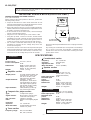 2
2
-
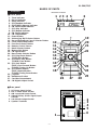 3
3
-
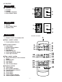 4
4
-
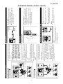 5
5
-
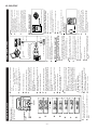 6
6
-
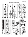 7
7
-
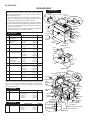 8
8
-
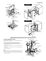 9
9
-
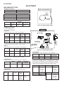 10
10
-
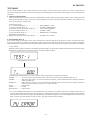 11
11
-
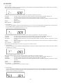 12
12
-
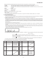 13
13
-
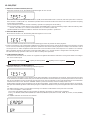 14
14
-
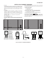 15
15
-
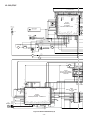 16
16
-
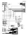 17
17
-
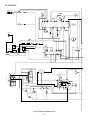 18
18
-
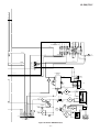 19
19
-
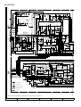 20
20
-
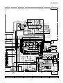 21
21
-
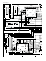 22
22
-
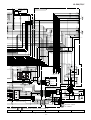 23
23
-
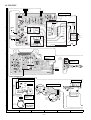 24
24
-
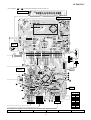 25
25
-
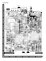 26
26
-
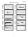 27
27
-
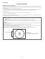 28
28
-
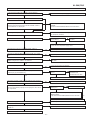 29
29
-
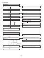 30
30
-
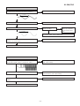 31
31
-
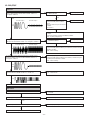 32
32
-
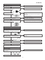 33
33
-
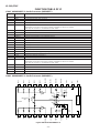 34
34
-
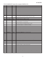 35
35
-
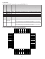 36
36
-
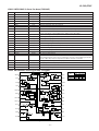 37
37
-
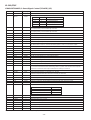 38
38
-
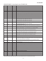 39
39
-
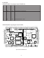 40
40
-
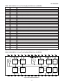 41
41
-
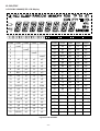 42
42
-
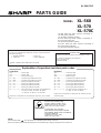 43
43
-
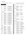 44
44
-
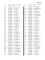 45
45
-
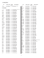 46
46
-
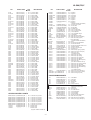 47
47
-
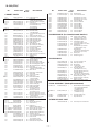 48
48
-
 49
49
-
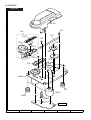 50
50
-
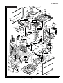 51
51
-
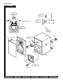 52
52
-
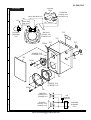 53
53
-
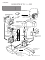 54
54
-
 55
55
-
 56
56


Sharp XL-560 User manual
- Category
- Cassette players
- Type
- User manual
Ask a question and I''ll find the answer in the document
Finding information in a document is now easier with AI