NOTICE - This service data sheet is intended for use by persons having electrical and mechanical
training and a level of knowledge of these subjects generally considered acceptable in the appliance
repair trade. The manufacturer cannot be responsible, nor assume any liability for injury or damage
of any kind arising from the use of this data sheet.
SAFE SERVICING PRACTICES
To avoid the possibility of personal injury and/or property damage, it is important that safe servicing practices
be observed. The following are examples, but without limitation, of such practices.
1. Before servicing or moving an appliance remove power cord from electrical outlet, trip circuit breaker
to OFF, or remove fuse.
2. Never interfere with the proper installation of any safety device.
3. GROUNDING: The standard color coding for safety ground wires is GREEN or GREEN WITH YELLOW
STRIPES. Ground leads are not to be used as current carrying conductors. It is extremely important
that the service technician reestablish all safety grounds prior to completion of service. Failure
to do so will create a potential safety hazard.
4. Prior to returning the product to service, ensure that:
• All electric connections are correct and secure.
• All electrical leads are properly dressed and secured away from sharp edges, high-temperature
components, and moving parts.
• All uninsulated electrical terminals, connectors, heaters, etc. are adequately spaced away from all
metal parts and panels.
• All safety grounds (both internal and external) are correctly and securely reassembled.
Oven Calibration
Set the electronic oven control for normal baking at 350°F. Obtain an average oven temperature after a
minimum of 5 cycles. Press Stop, Clear, O or Cancel to end Bake mode.
Temperature Adjustment
1. Set EOC to bake at 550°F.
2. Within 5 seconds of setting 550°F, press and hold the bake pad for approximately 15 seconds until a
single beep sounds (longer may cause F11 shorted keypad alarm).
3. Calibrationosetshouldappearinthedisplay.
4. Use the slew keys to adjust the oven temperature up or down 35°F in 5°F increments.
5. Oncethedesired(-35°to35°)osethasbeenapplied,PressStop, Clear, O or Cancel.
Note: Changing calibration aects normal Bake mode. The adjustments made will not change the Self-
Cleaning cycle temperature.
Modular Control Systems
This appliance is equipped with a modular system of controls. The modular system consists of various boards
which communicate with one another to drive cooking functions. Oven functions, if available, operate through
an oven user interface (UI or UIB) and an oven relay board. Cooktop functions, if available, operate through
a cooktop UI/UIB and a cooktop relay board. There may be additional boards which work within the system
todrivespecicfunctions(refertotheschematicsanddiagramsandthissheet).Lowvoltageoperatingand
communications power for the modular boards is provided through the wiring schemes. The boards that
generate low voltage operating and communications power depend upon the individual control system (refer
to the schematics and diagrams on this sheet). These voltages are only the operational voltages. Do not use
thesevoltagesasconrmationofcommunicationbetweentheboards.Communicationoccursthroughsoftware
programming on each board. This communication is not detectable by volt ohmmeters. The programming is
self-monitored and the UI displays will show error codes based on detected failures. The individual boards
arenoteldrepairable.Seetheschematicsanddiagramsincludedonthissheetformoreunit-specicdetails.
SERVICE DATA SHEET
Electric Range with ES 502I Electronic Oven Controls and Induction Smoothtop
808533505 REV C EN (2020/03)
IMPORTANT
DO NOT REMOVE THIS BAG
OR DESTROY THE CONTENTS
WIRING DIAGRAMS AND SERVICE
INFORMATION ENCLOSED
REPLACE CONTENTS IN BAG
Resistance (ohms)
1000 ± 4.0
1091 ± 5.3
1453 ± 8.9
1654 ± 10.8
1852 ± 13.5
2047 ± 15.8
2237 ± 18.5
2697 ± 24.4
Open circuit/infinite resistance
RTD SCALE
Temperature °F (°C)
32 ± 1.9 (0 ± 1.0)
75 ± 2.5 (24 ± 1.3)
250 ± 4.4 (121 ± 2.4)
350 ± 5.4 (177 ± 3.0)
450 ± 6.9 (232 ± 3.8)
550 ± 8.2 (288 ± 4.5)
650 ± 9.6 (343 ± 5.3)
900 ± 13.6 (482 ±7.5)
Probe circuit to case ground
Electronic Oven Control Fault Code Descriptions
Fault Code Likely Failure /Condition/Cause Suggested Corrective Action
F001,
F002,
F004,
F005
Touch failure 1. Disconnect power, wait 30 seconds and reapply power. If fault returns upon power-up replace the Oven User Interface board.
F003 Theovenuserinterfaceboardisincorrectlycongured. 1. Replace the oven user interface board. Make sure you install the latest revision available for this model.
F010 Oven temperature runaway: the cavity temperature has
been detected in excess of the maximum safe operating
temperature.
1. If oven is overheating, disconnect power. Check oven temperature probe (RTD) and replace if necessary. 2. If the oven temperature probe is good and if oven continues to overheat
when power is reapplied, replace the oven relay board.
F011 Stuck key: a key has been detected has pressed contin-
uously for 30 seconds or more.
1. If a key was pressed inadvertently for a long time this error code will be displayed. Make sure there is nothing (water, utensils) in contact with the keyboard. The fault code should go
away once the key is released and the Stop key is pressed. If the F011 error comes back when a key is pressed it means the error condition is still there. If the F011 error does not come
backitmeanstheerrorconditionisgoneandtheovencanbeused.2.Ifthefaultcodecannotbecleared,theboard/springsalignmentwithinthemechanicalenclosemaybeaected.
Reinstalltheboardwithintheenclosure.3.Ifreinstallingtheboarddidnotxtheproblemreplacetheovenuserinterfaceboard.
F012 Keyboardcongurationalarm:theovenuserinterface
board received from the touch micro a key code that
does not match the key map.
1.Verifytheunithasthepropercongurationisloaded,basedonthemodelnumberandpartscatalog.2.Replacetheovenuserinterfaceboardiftheproblempersists.
F013 Data written to non-volatile memory has failed
verication
1. Disconnect power, wait 30 seconds and reapply power. If fault returns upon power-up replace the oven user interface.
F015 Keyboard Error 1. Disconnect power, wait 30 seconds and reapply power. If fault returns upon power-up replace the oven user interface board.
F017 Theovenuserinterfaceboardisunabletocongure
the touch.
1.Disconnectpowertotheunit,wait30seconds,thenreapplypower.2.Verifytheunithastheproperovenuserinterfaceboardandconguration,basedonthemodelnumberand
parts catalog. 3. If fault persists, replace the oven user interface.
F018 Oven relay board failure (wiggler) 1. Replace the oven relay board.
F019 Theovenuserinterfaceboardisunabletocongurethe
oven relay board
1. Disconnect power to the unit, wait 30 seconds, then reapply power. 2. If fault returns, verify connection between the oven user interface board and the oven relay board (MACS1 or
MACS2 connector). 3. Verify the unit has the proper oven user interface board and oven relay board, based on the model number and parts catalog.
4. If fault persists, replace oven user interface board. 5. If fault persists, replace the relay board.
F020 Communication failure between the oven user interface
board and the Hob user Interface
1. Disconnect power, wait 30 seconds and reapply power. Check if error condition is still there. 2. Test wiring harness between oven user interface board and Hob user Interface (connector
MACS1 or MACS2). 3. If wiring harness is good replace oven relay board. 4. If the problem persists replace the oven user interface.
F022 Communication failure between the oven user interface
board and the oven relay board
1. Disconnect power, wait 30 seconds and reapply power. Check if error condition is still there. 2. Test wiring harness between oven user interface board and oven relay board (connector
MACS1 or MACS2). 3. If wiring harness is good replace oven relay board. 4. If the problem persists replace the oven user interface.
F023 Communication failure between the oven user interface
micro and the touch micro
1. Disconnect power, wait 30 seconds and reapply power. Check if error condition is still there. 2. If the problem persists replace the oven user interface.
F025, F027 The communication between the oven user interface and
the oven relay board cannot be initiated.
1. Disconnect power to the unit, wait 30 seconds, then reapply power. 2. If fault returns, verify connection between the oven user interface board and the oven relay board (MACS1 or
MACS2 connector). 3. Verify the unit has the proper oven user interface board and oven relay board, based on the model number and parts catalog. 4. If fault persists, replace relay board.
5. If fault persists, replace the oven user interface board.
F028, F029 The communication between the over user interface
micro and the touch micro cannot be initiated.
1.Disconnectpowertotheunit,wait30seconds,thenreapplypower.2.Verifytheunithastheproperovenuserinterfaceboardandconguration,basedonthemodelnumberand
parts catalog. 3. If fault persists, replace the oven user interface.
F030 Open oven temperature sensor (RTD) 1. Check probe circuit wiring for possible open or short condition. 2. Verify RTD resistance at room temperature (compare to probe resistance chart). If resistance does not match the
chart, replace the RTD probe. 3. If the problem persists replace the oven relay board.
F031 Shorted oven temperature probe (RTD)
F033 Meat probe temperature sensor shorted or too hot 1. The error is triggered if the meat probe sees a temperature in excess of 392°F. Make sure the meat probe was not used in such way that it could have seen such temperature. If the tip
of the probe is not inserted in the meat it will see the cavity temperature, which can be higher than 392°F (depending on the setpoint) and trigger the alarm.
2. When the meat probe is connected to the socket inside the oven cavity, if the meat probe is not fully inserted into the socket it may short the contacts and cause the error. Make sure the
probe is inserted as much as it can. 3. Verify meat probe resistance at room temperature. Compare to meat probe resistance chart. If the meat probe does not match the chart, replace it.
4. If the above steps failed to correct the problem, replace the oven relay board.
F050 A/D Out of Range: the oven relay board is unable to
readthestatusoftheswitches(door,MDL)
1. Clear error, cycle Power a couple of times and check if error is back, if so replace Power board. 2. Else replace Door switch plunger/s and reseat harness. 3. If error persists
checkMDL&Harness.
F090 MotorDoorLockmechanismfailure.Theovencontrol
doesnotseetheMotorDoorLockrunning.
1.Disconnectpowertotheunit,wait30seconds,thenreapplypower.Tryagaintomakethedoorlockorunlock(ex:initiateaLockoutoraCleancycle).
2.CheckiftheLockMotorisrunningornot.Ifitisnotrunning,testthewiringbetweentheLockMotorandtheovenrelayboard.Ifthewiringisgood,checkifthereis120VACatthemotor
when it is expected to run to see if the failure originates from a bad motor (120VAC present but not turning) or a problem with the relay board (J20 pin 10 on the oven relay board is the
outputtotheLockMotor).TheLockMotorcanalsobetestedbyapplying120VACdirectlytothemotor(unplugitfromtherelayboardrst).IftheLockMotordoesnotrunwhen120VAC
isappliedreplacetheLockMotorAssembly.Ifitistherelayboardthatdoesnotprovide120VACtotheLockMotorreplacetheovenrelayboard.
3.IftheLockMotorisrunningbuttheovencontrolcannotndthelockedorunlockedposition(ex:motorturnscontinuouslyuntilF90faultcodeisgenerated)theLockSwitchneedstobe
veried.CheckwiringbetweenLockSwitchandovenrelayboard.Verifywithohmmeteriftheswitchmakescontactproperly(verifycontinuitywithohmmeterwhentheswitchispressed).
IftheLockSwitchisdefectivereplacetheMotorLockAssembly.
4. If all above steps failed to correct the situation, replace the oven relay board.
F095 MotorDoorLockmechanismfailure.
TheMotorDoorLockdoesnotstoprunningortheLock
Switch sends an invalid signal.
1.TheproblemcanbecausedbyafaultyLockSwitchorbyadefectiveovenrelayboard.IftheMotorDoorLockisalwaysrunning(asiftherelaycontrollingitisstuckclosed)replace
the oven relay board.
2.IfthemotorisnotalwaysrunningreplacetheMotorLockAssembly.
F096 The oven door has been detected open during a Self-
Clean cycle.
1. This error occurs if the door switch has lost its contact during a Self-Clean cycle. Make sure the oven door closes well and fully presses on the door switch plunger when the door is
locked, and no one attempted to pull on the oven door during the Self Clean cycle. 2. Test continuity of wiring between the door switch and the oven relay board, make sure the door
switch is well connected. With an ohmmeter, verify the switch is closed when the plunger is pressed. If the door switch is found to be defective replace the door switch. 3. If the switch
and wiring are good and the problem persists, replace the oven relay board.
NEUTRAL
J8 1
L1
COOLING FAN
OVEN LIGHT CONVECTION FAN
WARMING ZONE
MOTOR DOOR LATCH
DLB-DOUBLE LINE BREAK
DOUBLE LIGNE DE PAUSE
K1
J6 BAKE
J7 CONV
J5 L1
J2
1
DOOR LATCH NO
MOTOR DOOR LATCH NO
DC GROUND
TEMPERATURE PROBE
DC GROUND
MEAT PROBE
MACS1 MACS2
GROUND
1
COMMON
13V
K9
MDL
K6
Oven
Light
K5
Conv
Fan
K8
Cooling
Fan
K7
Warming
Zone
(opt)
K2
Bake
K3
Convec-
tion
K4
Broil
L2 out
L2 in
RESISTANCE TEMPERATURE
DETECTOR
ELECTRONIC OVEN CONTROL (EOC) RELAY BOARD
Tech Sheet Abbreviations and Terminology
EOC = Electronic Oven Control ESEC = Electronic Surface Element Control TST = Touch Sensor Technology (touch control glass panel)
UIB = User Interface Board TSEC = Touch Sensor Electronic Control RTD = Resistance Temperature Device. (Temp Probe or Temp Sensor)
VSC = Variable Speed Control PS = Power Supply board (PS1 , PS2, etc.) TCO = Thermal Cut Out also “Thermo Disc” or “Thermal Limiter”
CIRCUIT
ANALYSIS
MATRIX
EOC RELAYS
L1 TO
BAKE
L1 TO
BROIL
L1 TO
CONV
L1 TO
MDL
L1 TO
CONV
FAN
L1 TO CONV
INDICATOR
LIGHT
DOOR
SWITCH
COM-NO
MDL
(certain
models)
COOKTOP
LOCKOUT
(some models)
BAKE X X* X
CONVECTION X X* X X X
BROIL X X
CLEAN X X X
UNLOCKED
LOCKING X X
LOCKED X
UNLOCKING X
DOOR OPEN
DOOR CLOSED X
COOKTOP ACTIVE X
NOTE: X= Check active circuits *=Alternates with bake element
GENERATOR BOARD 1
PLAQUE DU GENERATEUR
GENERATOR BOARD 2
PLAQUE DU GENERATEUR
LR COIL (180mm)
SPRING LOCATION
EMPLACEMENT DU
PRINTEMPS
BN001
BN002
BL002
BL001
TAB201
TAB202
BT200
BC004
BC003
ID JUMPER
BC001
BT100
TAB101
TAB102
L
N
LF COIL (180mm)
SPRING LOCATION
EMPLACEMENT DU
PRINTEMPS
LR COIL (180mm)
SPRING LOCATION
EMPLACEMENT DU
PRINTEMPS
BN001
BN002
BL002
BL001
TAB201
TAB202
BT200
BC004
BC003
ID JUMPER
BC001
BT100
TAB101
TAB102
L
N
LF COIL (180mm)
SPRING LOCATION
EMPLACEMENT DU
PRINTEMPS
Displayed
Power Level
Niveau de
puissance
aché
Power
Level %
Niveau
d'énergie
L 4.0
2 12.0
3 17.0
4 19.0
5 21.0
6 31.0
7 45.0
8 54.0
9 64.0
H 100.0
P 156
Electronic Surface Element Control (ESEC)
This range is equipped with an Electronic Surface Element Control (ESEC), which precisely controls the smoothtop cooking elements at multiple settings. For the user, the elements are operated by pressing the touch pads located on the control panel for the desired
settings. The control settings are shown in 1-digit displays.
Hot Surface indication - If any of the induction elements are hot, a hot surface light will remain ON until the cooktop cools.
ESEC lockout feature -Theelectronicovencontrol'sself-cleanandControlLockoutfeatureswillnotoperatewhenasurfaceelementisON.Conversely,thesurfaceelementscontrolledbytheESECwillnotoperatewhenanovencontrolself-cleanorControl
Lockoutmodeisactive.Whentheovencontrolisinaself-cleanorControlLockoutmode, will appear in the oven control display to signify that the surface heating elements are locked out.
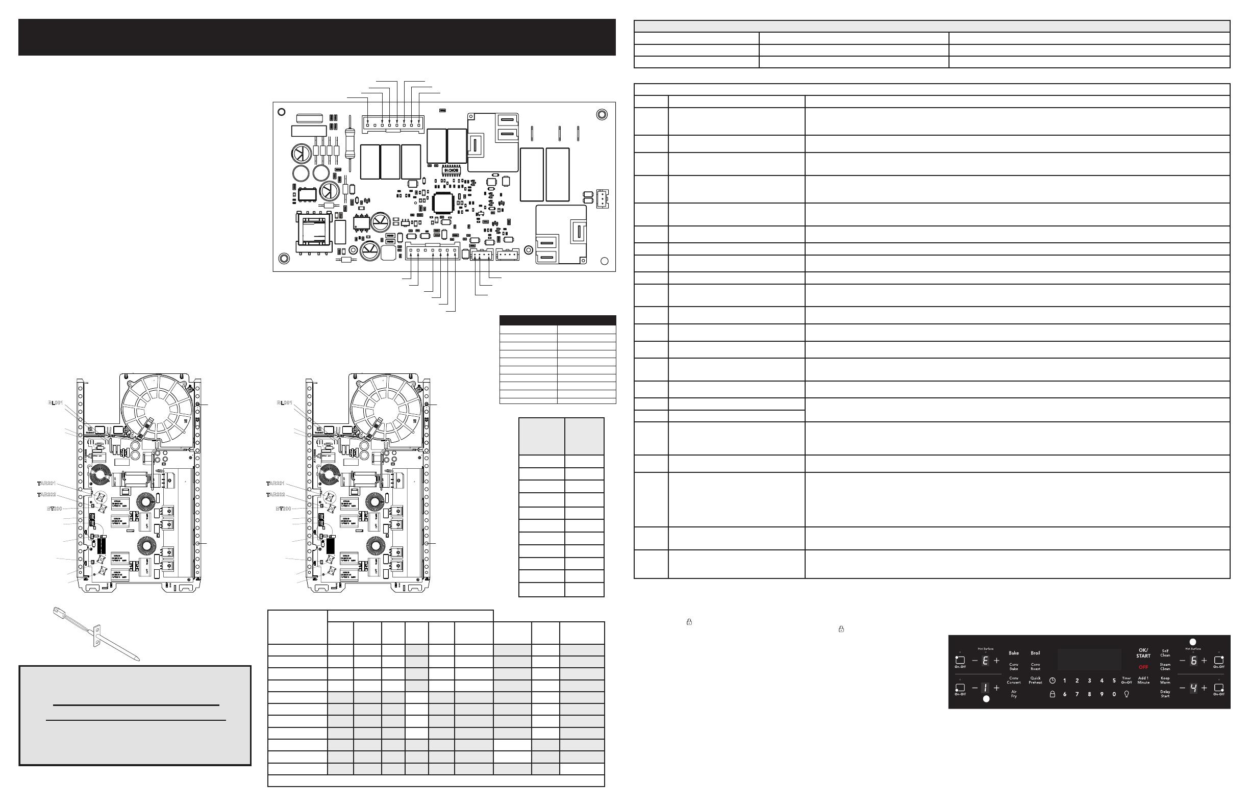
Error notication in an induction system
Inductionrelatedalarmsaredisplayedusingall4displaysoftheuserinterface.TheRearLeftdisplayisusedtonotifytheuserthatthe
messagebeingdisplayedisanerrorandisrepresentedwithan“E”inthedisplay.TheFrontLeftdisplayisusedtoshowwhichinduction
generator board is generating the error.
1.TheFrontLeftdisplayshowing“1”aboveindicatesthattheleftgeneratorboardisproducingtheerror.Ifdisplayshowsa“2”,thisindicatesthattherightgeneratorboardisproducingtheerror.Ifdisplayshowsa“0”,thisindicatesthattheissuewasgeneratedby
the cooktop control and not the induction generator.
2. The Front Right and Rear Right displays display the actual error. An example of a stuck cooling fan on the left induction generator board (E164) is shown above.
Replacing the ES502I control* – When replacing the oven/cooktop control in the backguard, DO NOT over tighten the screws that secure it. Upper and lower support brackets should be reinstalled.
* Please note: Electronic boards are very sensitive to static electricity. Static electricity can permanently damage electronic boards. Before handling these parts, be sure to drain static electricity from your body by properly grounding yourself.
ESEC system components -
The ESEC system consists of the following components:
ES502I oven/cooktop control (EOC) - circuit boards mounted in plastic chassis.
Induction control assembly - circuit boards in plastic housings mounted under the cooktop on a metal tray with four screws.
Notes on replacing parts
Replacing an induction generator board – When replacing an induction generator board under the cooktop, do not over-tighten the 2
screws that secure each board to the range. Over-tightening the screws can damage the plastic housings holding the circuit boards.
Replacing an induction element
Ensure correct coil location.

