
Cyclops 160B
© Land Instruments International, 2007-2012
User Guide
Issue 2, January 2012
Publication Nº 806458
Language: English

Health and Safety Information
Read all of the instructions in this booklet - including all the WARNINGS and CAUTIONS
- before using this product. If there is any instruction which you do not understand.
DO NOT USE THE PRODUCT.
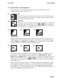
Safety Signs
WARNING
Indicates a potentially hazardous situation which, if not avoided, could result in death or
personal injury.
CAUTION
Indicates a potentially hazardous situation which, if not avoided, could result in minor or
moderate injury to the user or users, or result in damage to the product or to property.
NOTE
Indicates a potentially hazardous situation which, if not avoided, could result in damage or the loss of
data.
Equipment Operation
Use of this instrument in a manner not specied by Land Instruments International may be hazardous.
Read and understand the user documentation supplied before installing and operating the equipment.
Protective Clothing, Face and Eye Protection
It is possible that this equipment is to be installed on, or near to, machinery or equipment operating at
high temperatures and high pressures. Suitable protective clothing, along with face and eye protection
must be worn. Refer to the health and safety guidelines for the machinery/equipment before installing
this product. If in doubt, contact Land Instruments International.
Electrical Power Supply
Before working on the electrical connections, all of the electrical power lines to the equipment must
be isolated. All the electrical cables and signal cables must be connected exactly as indicated in these
operating instructions. If in doubt, contact Land Instruments International.
Storage
The instrument should be stored in its packaging, in a dry sheltered area.
Unpacking
Check all packages for external signs of damage. Check the contents against the packing note.
Lifting Instructions
Where items are too heavy to be lifted manually, use suitably rated lifting equipment. Refer to the
Technical Specication for weights. All lifting should be done as stated in local regulations.
IMPORTANT INFORMATION - PLEASE READ

Contact Us
UK - Droneld
Land Instruments International
Tel: +44 (0) 1246 417691
E-Mail: [email protected].uk
Web: www.landinst.com
USA - Pittsburgh
AMETEK Land, Inc.
Tel: +1 412 826 4444
E-Mail: [email protected]
Web: www.ametek-land.com
For further details on all LAND/Ametek ofces, distributors and representatives, please visit
our websites.
Return of Damaged Goods
IMPORTANT If any item has been damaged in transit, this should be reported to the carrier and to the
supplier immediately. Damage caused in transit is the responsibility of the carrier not the supplier.
DO NOT RETURN a damaged instrument to the sender as the carrier will not then consider a claim. Save
the packing with the damaged article for inspection by the carrier.
Return of Goods for Repair
If you need to return goods for repair please contact our Customer Service Department. They will be
able to advise you on the correct returns procedure.
Any item returned to Land Instruments International should be adequately packaged to prevent damage
during transit.
You must include a written report of the problem together with your own name and contact information,
address, telephone number, email address etc.
Design and Manufacturing Standards
The Quality Management System of Land Instruments International is approved to BS EN ISO 9001 for
the design, manufacture and on-site servicing of combustion, environmental monitoring and non-contact
temperature measuring instrumentation.
Approvals apply in the USA
This instrument complies with current European directives relating to Electromagnetic
Compatibility 89/336/EEC and Low Voltage Directive 73/23/EEC.
Operation of radio transmitters, telephones or other electrical/electronic devices in close proximity
to the equipment while the enclosure doors of the instrument or its peripherals are open, may cause
interference and possible failure where the radiated emissions exceed the EMC directive.
The protection provided by both CE and IP classications to this product may be invalidated if alterations
or additions are made to the structural, electrical, mechanical or pneumatic parts of this system. Such
changes may also invalidate the standard terms of warranty.
Copyright
This manual is provided as an aid to owners of Land Instruments International’s products and contains
information proprietary to Land Instruments International. This manual may not, in whole or part, be
copied, or reproduced without the expressed written consent of Land Instruments International Ltd.
Copyright © 2012 Land Instruments International.

Cyclops 160B User Guide

Cyclops 160BUser Guide
Contents
1 Introduction 1
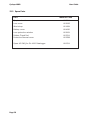
2 Specications 3
3 Thermometer description 4
4 Thermometer Power Supply 5
5 Thermometer controls 7
6 Optics 9
7 Display Panel Modes 12
8 Operational (Trigger) Modes 21
9 Thermometer Operation 24
10 Bluetooth
®
wireless communication 28
11 Emissivity 29
12 Maintenance 33
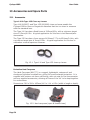
13 Accessories and Spare Parts 34
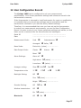
14 User Conguration Record 37
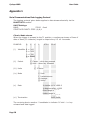
Appendix 1 38
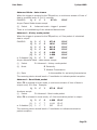
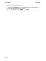
Appendix 2 41
The Bluetooth
®
word mark and logos are registered trademarks owned by Bluetooth SIG, Inc. and any use of such marks by Land
Instruments International is under license.

Cyclops 160B User Guide
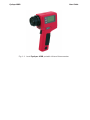
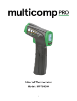
Fig. 1-1 Land Cyclops 160B portable infrared thermometer

Cyclops 160BUser Guide
Page 1
1 Introduction
1.1 General Introduction
This publication gives you the information required to safely operate Land
Cyclops 160B portable thermometers.
It is important to check all equipment with which you have been supplied,
and read all the literature provided with the Land Cyclops 160B before using
the thermometer for the rst time. Additionally, keep all supplied literature
readily available, for reference when the equipment is in general use.
The equipment must only be used and maintained by suitably trained
personnel, capable of following the procedures and guidelines given in this
User Guide and the Cyclops 160B Quick-Start Guide.
1.2 About Cyclops 160B Portable Thermometers
The Land Cyclops 160B is a highly accurate, portable, short wavelength
infrared thermometer, designed to measure and display temperatures in the
range 200 to 1400°C/392 to 2552°F. The thermometer can also measure and
display these temperatures in Kelvin and °Rankine.
The target temperature is measured and displayed in four simultaneous
measurement types: ‘Peak’, ‘Continuous’, ‘Average’ and ‘Valley’. You can
choose which of these measurements is displayed in the internal viewnder
display.
The wide angle (9°) eld of view and the small (1/3°) measurement
point ensure that the target is dened clearly and accurately. The focus
is continuously variable from one metre to innity. Auxiliary lenses are
available, which provide close focus capability.
The emissivity compensation setting can be controlled digitally, via the simple
to use, icon-based menu system, which is available at the touch of a button.
The operating waveband has been chosen specically to minimise errors due
to uncertainty in emissivity, whilst eliminating the effects of atmospheric
absorption.
The Cyclops 160B features user-friendly ‘Bluetooth’ communications.

Cyclops 160B User Guide
Page 2
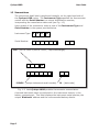
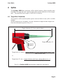
1.3 Nomenclature
The instrument detail label is positioned centrally, on the right-hand side of
the Cyclops 160B casing. The Instrument Type species the thermometer
variant and the Serial Number is a unique identication number,
incorporating the manufacture date code (see Fig. 1-2)
Upon receipt of the instrument, make a note of the Instrument Type and
Serial Number in the spaces provided below.
Instrument Type:
Serial Number:
Fig. 1-2 Land Cyclops 160B portable thermometer nomenclature
A second instrument label is positioned on the instrument chassis, in the
battery compartment. This label displays the instrument serial number, the
unique ‘Bluetooth’ address and the recommended battery details.
160 - (200 to 1400°C/392 to 2552°F, 1.6µm wavelength)
123456 - (unique instrument serial number) 01 - (date code)
B
B1 6 0

Cyclops 160BUser Guide
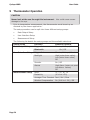
Page 3
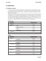
2 Specifications
Temperature range: 200 to 1400°C / 392 to 2552°F (operating)
200 to 1300°C / 392 to 2372°F (specied)
Viewnder display: 4-digit temperature in 1° steps
External display: Peak, Continuous, Average and Valley
temperatures on LCD display panel
Optical system: 9° eld of view with 1/3° measuring circle;
single-lens-reex system; with eyepiece
adjustment from -3.75 to +2.5 diopters
Focusing: 1m/39.4in. to innity (standard) from
body datum nominally 460 to 630mm/18.1
to 24.8in. (135 c.u.lens) nominally
217mm/8.5in. xed focus (110 c.u. lens)
Minimum target diameter: 4.8mm/0.19in at 101.4cm/39.9in (standard)
2.0mm/0.08in (135 close-up lens)
0.5mm/0.02in (110 close-up lens)
Detector: InGaAs photocell
Spectral response: nominally 1.6µm
Emissivity adjustment: 0.10 to 1.20, in 0.01 steps
Response time: digital display update: 0.5 seconds
(approx.); peak and valley operation:
acquisition time 30ms (approx.)
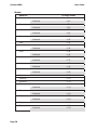
Operating temperature range: 0 to 50°C (32 to 122°F)
Storage temperature range: -20 to 60°C (-4 to 140°F)
Accuracy: <(±0.25% /C) +2°C
Repeatability: <1°C
Drift with ambient temperature: <0.15%(C)/10°C, <0.10%(F)/10°F
Power source: one 9V dry battery (Duracell 6LR61/MN1604
or equivalent); typical alkaline battery life:
>100hrs in ‘from-factory’ conguration
IP rating: IP51
Dimensions: 210 x 70 x 140mm / 8¼ x 2¾ x 5½in.
Weight: 800g/1lb12oz (without battery)
Standard accessories: lens cap; 9V alkaline battery; protective
window; wrist strap
Optional accessories: type 135 and 110 close-up lenses; protective
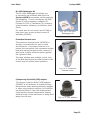
hard carrycase; DL-1000 datalogging kit/
interface cables; thermal glove; LER adapter

Cyclops 160B User Guide
Page 4
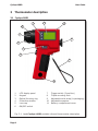
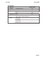
3 Thermometer description
3.1 Cyclops 160B
1 LCD display panel 7 Trigger switch (2 position)
2 Keypad 8 Tripod mounting hole
3 Optical focusing ring 9 Adjustable wrist strap (in packaging)
4 Protective window 10 Adjustable eyepiece
5 Lens cap 11 Battery compartment cover
6 ON/OFF switch
Fig. 3-1 Land Cyclops 160B portable infrared thermometer description
1
2
3
4
5
6
7
8
9
10
11

Cyclops 160BUser Guide
Page 5
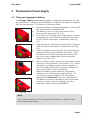
4 Thermometer Power Supply
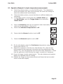
4.1 Fitting and changing the Battery
The Cyclops 160B portable thermometer is designed to be powered by a 9V
dry cell battery. A Duracell 6LR61/MN1604 (or equivalent) battery is supplied
with the thermometer. The battery is tted as follows:
1) Before inserting or changing the battery, ensure that
the thermometer is switched OFF.
2) The battery cover is on the top surface of the
thermometer body (see Fig. 4-1).
3) Press down on the nger grip of the battery cover to
disengage the cover catch and slide the cover back
to fully expose the battery compartment (see Fig.
4-2).
4) Align the battery such that the terminals correspond
with the label in the battery compartment (see Fig.
4-3).
5) Insert the battery, ensuring that the contact springs
engage centrally into the battery terminals. Slide
the battery cover back into place and ensure that
the cover catch engages with the thermometer
chassis (see Fig. 4-4).
6) With the battery tted, switch the instrument on and
check for correct operation (see Section 7.0). When
switched on, a battery power indicator appears in
the LCD display panel, which gives an indication of
how much power is left in the battery.
When the battery needs replacing, the battery
indicator on the LCD display panel will ash. To
prolong the remaining battery life, the display
backlight and ‘Bluetooth’ should be switched off.
The battery should be changed as soon as possible
in order to ensure that the readings from the
instrument remain within specication.
Fig. 4-1
Fig. 4-2
Fig. 4-3
Fig. 4-4
Note
It is recommended that a fully charged spare battery is kept with the
thermometer at all times.

Cyclops 160B User Guide
Page 6
To preserve battery lifetime, the thermometer has the following power saving
features:
• If the thermometer is in Menu Mode for over one minute without any key
being pressed, the display returns to Measure Mode.
• If the thermometer is in Measure Mode for over two hours without any
key being pressed, the instrument is switched off.

Cyclops 160BUser Guide
Page 7
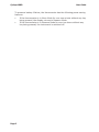
5 Thermometer controls
5.1 ON/OFF Switch
The On/Off switch is on the left-hand side of the
thermometer (see Fig. 3-1, item 6). The switch has two
push buttons, Off (a) and On (b).
A single press of a switch will activate/de-activate the
unit.
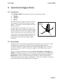
5.2 Trigger Operation
The Trigger (c) is on the thermometer handle (see Fig.
3-1, item 7). The trigger function depends upon the
chosen mode of operation: Classic, History or Burst.
In Classic mode, the trigger has one function, to read
and display temperature. In History and Burst modes,
the trigger activates advanced functions within the
thermometer (see Section 8).
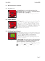
5.3 LCD Display Panel & Keypad
The LCD display panel (d) is on the left-hand side of the
thermometer body (see Fig. 3-1, item 1). It operates in
two modes: Measure Mode and Menu Mode.
In Measure Mode, the scene temperature and
thermometer setup information (including battery life
indication) is displayed.
In Menu Mode, the function menus of the thermometer
can be accessed. You can select functions and set the
required parameters, as described in Section 7.
There are three action keys on the Keypad to the left of
the main display:
(Scroll Up), (Scroll Down) and
(Enter/select). These are used to navigate around
the various menus and displays.
Fig. 5-2
c
Fig. 5-1
b
a
Fig. 5-3
d

Cyclops 160B User Guide
Page 8
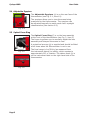
5.4 Adjustable Eyepiece
The Adjustable Eyepiece (e) is on the rear face of the
thermometer (see Fig. 3-1, item 10).
The eyepiece allows you to view the scene being
measured by the thermometer. The eyepiece can
be adjusted manually to match each user’s eyesight
characteristics (See section 6.3).
5.5 Optical Focus Ring
The Optical Focus Ring (f) is on the lens assembly
at the front of the thermometer (see Fig. 3, item 3).
The focus ring allows you to manually adjust the lens
assembly and sharpen the scene in view.
A protective lens cap (g) is supplied and should be tted
at all times when the thermometer is not in use.
The focal range is 1m/39.4in (as measured from
the instrument datum) to innity, which equates to
approximately 90° of rotation. The datum mark (h) is
on the instrument label on the right-hand side of the
thermometer.
Fig. 5-5
g
f
Fig. 5-6
h
Fig. 5-4
e

Cyclops 160BUser Guide
Page 9
6 Optics
The Cyclops 160B has a precision reex optical system, which provides user-
focusable ‘through the lens’ sighting and gives precise denition of the target
spot. The specied focal range is 1m/39.4in to innity.
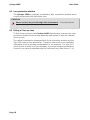
6.1 Target Size Calculation
The precision reex optical system gives a narrow eld of view (180:1 to 98%
energy).
As the instrument is focusable, you can calculate an approximate target size
from the information given in Fig. 6-1.
Target distance (D) from optical datum
Target diameter (T)
Optical
datum
Field of view
Target size (T) (mm) = target distance (D) from optical datum (mm) - 100
eld of view (180)
or
Target size (T) (in) = target distance (D) from optical datum (in) - 4
eld of view (180)
Fig. 6-1 Cyclops 160B thermometer target size calculation

Cyclops 160B User Guide
Page 10
6.2 Lens protection window
The Cyclops 160B is supplied, as standard, with a protective window which
covers and protects the instrument lens.
CAUTION
Never look at the sun through this instrument - this could cause
severe damage to the eye.
6.3 Fitting a Close-up Lens
To t a close-up lens to the Cyclops 160B thermometer, unscrew the clear
protection window from the lens assembly and replace it with the relevant
close-up lens.
The optical transmission characteristics of the protection window and the
Type 135 close-up lens are similar. Therefore, there will be no signicant
calibration error, so window compensation is not required. If a type 110
close-up lens is used, it will be necessary to set the window transmission
function to a value as specied with the individual lens (See Section 7.4).

Cyclops 160BUser Guide
Page 11
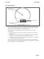
Fig. 6-2 Cyclops 160B eyepiece optics
Display panel
Temperature
reading
Target graticule
(1/3° circle)
The eyepiece allows you to look into the thermometer and view the target
scene. Accurate target denition is provided by the wide angle (9°) eld of
view and small, clearly dened (1/3°) target graticule.
The eyepiece can be focused manually to match each user’s eyesight
characteristics:
1) Use the viewnder to view a plain, brightly lit background, such as a
blank wall.
2) Rotate the rubber eye cup to bring the graticule circle to the sharpest
possible focus. The eyepiece is now adjusted to your eye.
3) Adjust the main focusing ring to bring the target scene to the sharpest
possible focus on the graticule circle.
When a temperature reading is taken (the trigger pressed), the measured
value is displayed in the eyepiece display panel. The temperature is displayed
in the units selected from the Main Menu.
6.4 Eyepiece Optics

Cyclops 160B User Guide
Page 12
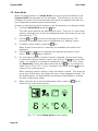
7 Display Panel Modes
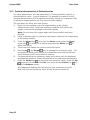
7.1 Introduction
The LCD display panel has two basic modes of operation:
• Measure Mode
• Menu Mode
When the thermometer is switched on, an introduction screen is displayed.
This screen times-out automatically and is replaced by the Measure Mode
display.
To access the Menu Mode from the Measure Mode, press the
(Enter/
select) key on the keypad.
Note
In the event of a fault causing loss of on-board memory, an error message
will be displayed near the bottom of the screen. For a list of error codes and
their meanings, see Appendix 2
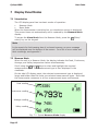
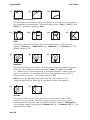
7.2 Measure Mode
When the unit is in Measure Mode, the display indicates the Peak, Continuous,
Average, and Valley temperature values simultaneously.
Scroll using the
and keys to select and highlight the required
measurement type. This measurement type is then displayed in the
viewnder.
On the side LCD display panel, the selected measurement type is displayed
larger and bolder than the three non-selected measurement types. Note that
the thermometer measures in all four measurement types continuously.
Fig. 7-1 Typical Measure Mode display
Peak reading
Continuous reading
Average reading
Valley reading

Cyclops 160BUser Guide
Page 13
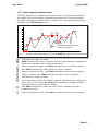
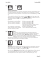
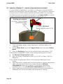
7.2.1 Peak temperature measurement
The Peak temperature measurement mode is used to measure and display
information about the highest temperatures recorded by the thermometer.
The peak temperature values can be viewed in the instrument eyepiece and
streamed to the Bluetooth output.
a Thermometer trigger pressed
b Peak temperature value on display jumps to instantaneous temperature
value and rises with rise in object temperature
c Object temperature falls, last Peak temperature value held on display
d New Peak temperature value reached, display updated
e Object temperature falls, last Peak temperature value held on display
f Trigger released, last Peak temperature value frozen on display
g Thermometer trigger pressed
h Peak temperature value on display jumps to instantaneous temperature
value (even if lower than last Peak value held before trigger release).
Peak temperature value held on display
i New Peak temperature value reached, display updated as object
temperature rises
j Object temperature falls, last Peak temperature value held on display
Fig. 7-2 Graphical representation of typical Peak temperature measurement
b
f
g
c d
e
h
a
i
j
Fluctuating temperature
reading of object

Cyclops 160B User Guide
Page 14
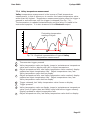
7.2.2 Continuous temperature measurement
Continuous temperature measurement provides the real-time observed
temperature value. The temperature is updated continuously and the value is
viewed in the instrument eyepiece.
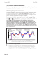
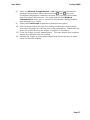
7.2.3 Averaged temperature measurement
Averaged temperature measurement gives a ‘smoothed’ temperature value.
To use the averaging function, press and hold down the trigger. The
averaging function operates for the period during which the trigger is held
down. Averaging stops when the trigger is released.
The response time of the averaging is controlled by the Averager Time
Constant setting in Menu Mode. The options are Slow, Mid and Fast. Use
the
and keys to select the required option from the menu.
With a Fast time constant selected, the temperature reading closely
matches the object temperature. Only the most rapid uctuations in the
input are smoothed in the output. With a Slow time constant selected, the
temperature reading is much smoother, displaying more of a ‘trend’ value
rather than showing any rapid changes. With a Mid time constant selected,
the temperature reading is calculated somewhere between the fast and slow
time constant values.
Fig. 7-3 Graphical representation of typical Averaged temperature
measurement with Slow, Mid and Fast time constants
a
b
Slow
averager time
constant
Fast averager
time constant
Mid averager
time constant
Fluctuating temperature
reading of object
a Thermometer trigger pressed
b Averaging is initiated at the rst instantaneous temperature value.
Averaged temperature values are calculated, displayed and updated
every half second whilst the trigger remains depressed. The nal
averaged value is held on the side display when the trigger is released.
Page is loading ...
Page is loading ...
Page is loading ...
Page is loading ...
Page is loading ...
Page is loading ...
Page is loading ...
Page is loading ...
Page is loading ...
Page is loading ...
Page is loading ...
Page is loading ...
Page is loading ...
Page is loading ...
Page is loading ...
Page is loading ...
Page is loading ...
Page is loading ...
Page is loading ...
Page is loading ...
Page is loading ...
Page is loading ...
Page is loading ...
Page is loading ...
Page is loading ...
Page is loading ...
Page is loading ...
Page is loading ...
Page is loading ...
Page is loading ...
-
 1
1
-
 2
2
-
 3
3
-
 4
4
-
 5
5
-
 6
6
-
 7
7
-
 8
8
-
 9
9
-
 10
10
-
 11
11
-
 12
12
-
 13
13
-
 14
14
-
 15
15
-
 16
16
-
 17
17
-
 18
18
-
 19
19
-
 20
20
-
 21
21
-
 22
22
-
 23
23
-
 24
24
-
 25
25
-
 26
26
-
 27
27
-
 28
28
-
 29
29
-
 30
30
-
 31
31
-
 32
32
-
 33
33
-
 34
34
-
 35
35
-
 36
36
-
 37
37
-
 38
38
-
 39
39
-
 40
40
-
 41
41
-
 42
42
-
 43
43
-
 44
44
-
 45
45
-
 46
46
-
 47
47
-
 48
48
-
 49
49
-
 50
50


Ask a question and I''ll find the answer in the document
Finding information in a document is now easier with AI
Related papers

Other documents
-
 Eurolec IR151 Operating instructions
-
 multicomp pro MP780004 Operating instructions
-
Camco 44313 Installation guide
-
Ametek LAND UNO User Supplement
-
Dostmann Proscan 520 Profi-Infrarot-Thermometer User manual
-
SEFRAM 9816B User manual
-
Traceable 4477 Owner's manual
-
 Turner Cyclops 7 User manual
-
Shinko IRT-300-AT, AS User manual
-
Mastech MS6530T User manual


