Page is loading ...

1
WARNING: Because of the possible danger to person(s) or
property from accidents which may result from the improper
use of products, it is important that correct procedures be
followed. Products must be used in accordance with the
engineering information specified in the catalog. Proper
installation, maintenance and operation procedures must
be observed. The instructions in the instruction manuals
must be followed. Inspections should be made as necessary
to assure safe operation under prevailing conditions. Proper
guards and other suitable safety devices or procedures as
may be desirable or as may be specified in safety codes
should be provided, and are neither provided by Baldor
Electric Company nor are the responsibility of Baldor
Electric Company. This unit and its associated equipment
must be installed, adjusted and maintained by qualified
personnel who are familiar with the construction and
operation of all equipment in the system and the potential
hazards involved. When risk to persons or property may be
involved, a holding device must be an integral part of the
driven equipment beyond the speed reducer output shaft.
DODGE ISAF Bearings Hydraulic Mount Patent # 7,866,894
Instruction and Lubrication Manual
These instructions must be read thoroughly before installation or operation. Instruction videos can be found on www.dodge-pt.com.
WARNING: To ensure the drive is not unexpectedly started,
turn off and lock-out or tag power source before proceeding.
Failure to observe these precautions could result in bodily
injury.
INSPECTION
Inspect shaft to ensure it is smooth, straight, clean and within
commercial tolerances. All weight must be removed from the
shaft prior to installing.
TOOLS REQUIRED FOR PROPER
INSTALLATION AND REMOVAL
• Hydraulic Hand Pump, Hose and Fluid
• 1/4 - 18 NPT Fitting
• 0-5000 psi Pressure Gauge for Hydraulic Pump
• M6 Allen Wrench
• Magnetic Base Dial Indicator
• Torque Wrench with Appropriate Socket (See Table 3)
• Drift and Hammer
• Rubber Mallet
• Hand File
• Adjustable Wrench
• 1/2 inch diameter Barring Rods (2), approximately 8”
in length
MOUNTING PROCEDURE
NOTE: Misalignment must be within ± 1/2º.
Install Non-Expansion (Fixed) Bearing First
1. Remove lubricatable auxiliary seals from OD of Mount and
Dismount Nuts. Be careful not to damage the two O-rings in
bore of seal. Note orientation of seal.
2. Remove lock clips located on the face of both Mount and
Dismount Nuts.
NOTE: The face of the Mount Nut contains 7 sets of equally
spaced drilled and tapped holes and an instruction plate.
The Dismount Nut contains three sets of drilled and tapped
holes located 120° apart.
1/4 NPTF
1/4 NPTF
Mount Nut Dismount Nut
Figure 1 - Mount Nut and Dismount Nut
3. Scribe a line on Adapter face and Dismount Nut.
4. Rotate Dismount Nut counter clockwise two full rotations.
The Dismount Nut must remain loose during the mounting
procedure but should never be removed. Without loosening
the dismount nut, the dismount unit piston will make contact
with the bearing unit as it travels up the adapter. (See Figure
3) This will not allow the bearing to move up the adapter and
tighten properly.
5. Rotate Mount Nut counter clockwise one full rotation and tap
on the face with a rubber mallet. This will drive the adapter
toward the Dismount Nut end and ensures the Adapter is
fully expanded.
6. Slide one lubricatable auxiliary seal on shaft in same
orientation as when it was removed.
7. Slide bearing on shaft and into position. If bearing will not
slide onto the shaft repeat Step 5.
8. Using a spanner or barring rod rotate Mount Nut clockwise
until snug. This allows the mount nut piston to be in full
contact with the bearing unit so that when the mount nut
is pressurized with hydraulic uid, the piston will push the
bearing unit up the adapter and properly tighten.
Table 1 - Starting Position Pressure
Bearing
Series
Bore
Starting
Position
Final
Position
Recommended Shaft
Tolerances
(psi) (in.) (in.)
22232 5-7/16" - 5-1/2" 200 0.036
+.000
-.005
22234 5-15/16" - 6" 220 0.038
22236 6-7/16" - 6-1/2" 210 0.04
+.000
-.006
22238 6-15/16" - 7" 200 0.042
22244 7-1/2" - 8" 250 0.049
23048 8-7/16" - 9" 210 0.05
+.000
-.007
23056 9-15/16" - 10-1/2" 240 0.057
23060 10-15/16" - 11" 210 0.061
+.000
-.008
23068 12-7/16" - 12-1/2" 240 0.069
23076 13-15/16" - 4" 225 0.076
23080 15" 250 0.08
23152 9-7/16" - 9-1/2" 430 0.054
+.000
- .007
23156 10" - 10-1/2" 400 0.058
23160 10-15/16" - 11" 345 0.062
+.000
-.008
23164 11-15/16" - 12 390 0.066
23168 12-7/16" - 12-1/2" 440 0.071
23172 13-7/16" - 13-1/2" 435 0.075
23176 13-15/16" - 14" 400 0.078
9. Attach a hydraulic pump to either of the two 1/4 - 18 NPT

2
Fitting hydraulic ports found on the Mount Nut. They contain
pipe plugs and are located on the face and OD of the nut
180° apart.
10. Actuate hydraulic pump until Starting Position Pressure
(Table 1) is attained.
11. Install a magnetic base indicator or displacement gauge.
• Displacement Gauge: Install gauge in hydraulic port on
face of Mount Nut. Follow instructions included with
gauge for proper installation.
• Magnetic Base Indicator: Place on the shaft with the
anvil on face of inner unit as shown in Figure 2.
12. Zero the Indicator.
13. Actuate hydraulic pump until indicator indicates movement
as shown in the nal position column of Table 1. Periodically
check the dismount nut to ensure that it is still loose during
the mounting process.
NOTE: If hydraulic pressure reaches 3,000 psi prior to
attaining Final Position, abort procedure by releasing
pressure to hydraulic nut. Check to ensure Dismount
Nut is still loose. If not, rotate it counter clockwise 1 full
rotation and repeat Step 13.
14. Remove Indicator from shaft or displacement gauge from
mount nut.
15. Release pressure to hydraulic pump and rotate Mount
Nut clockwise until snug. This forces the hydraulic fluid
back into the pump. Failure to complete this step may
result in the locknut loosening during operation after it
is tightened.
16. Remove hydraulic attachment from Mount Nut and insert
supplied pipe plug.
17. Using a spanner or drift and hammer, drive the Mount Nut
clockwise until the lock clip can be inserted into one of the
adapter slots and aligned with the drilled and tapped lock
clip holes.
NOTE: Always tighten, never loosen, the Mount Nut.
18. Insert lock clip and tighten lock clip bolts.
19. Using a barring rod, rotate Dismount Nut clockwise until
snug.
20. Insert lock clip into one of the adapter slots and align with
drilled and tapped lock clip holes located on the face of the
Dismount Nut. If the holes are not aligned with the adapter
slot rotate the Dismount Nut COUNTER CLOCKWISE until
the lock clip can be installed.
21. Insert and tighten lock clip bolts.
22. Place the stabilizing ring over Mount Nut.
23. Install the lubricatable auxiliary seals onto the Mount and
Dismount Nuts. Ensure all burrs or sharp edges are led off
the shaft, so that the o-rings in the seals
are not damaged.
Install the Expansion (Float) Bearing
1. Follow the same steps as outlined for the Non-Expansion
bearing.
2. Skip Step 22 since t
he stabilizing ring is not needed.
DISMOUNT PROCEDURE
1. Remove lock clips from the Mount and Dismount nuts.
2. Remove lubricatable auxiliary seal from OD of Mount and
Dismount Nuts. Be careful not to damage the two O-rings in
bore of seal. Remove weight from shaft.
3. Scribe a line on the Adapter face and Mount Nut.
4. Incorporating a spanner or drift and hammer, rotate the
Mount Nut counter clockwise two full rotations. The Mount
Nut must remain loose during the dismounting procedure,
but should never be removed. Without loosening the mount
nut, the mount nut piston will make contact with the bearing
unit as it travels down the adapter. (See Figure 3) This will not
allow the bearing to move down the adapter and loosen from
the shaft properly.
5. Using a spanner or barring rod, rotate the Dismount Nut
clockwise until snug. This allows the dismount nut piston
to be in full contact with the bearing unit so that when the
dismount nut is pressurized with hydraulic uid, the piston
will push the bearing unit down the adapter and properly
loosen from the shaft.
6. Attach the hydraulic pump to either of two supplied 1/4 - 18
NPT hydraulic ports found on Dismount Nut. The hydraulic
ports contain pipe plugs and are located on the face and OD
of the nut 180° apart.
7. Actuate the hydraulic pump until the pressure reading rises
SHAFT
MAGNETIC
BASE
MOUNT
NUT
DIAL
INDICATOR
Figure 2 - Magnetic Base Indicator Placement

3
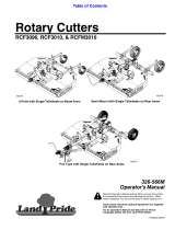
Mount Nut
Piston
Mount Nut
Triple Lip
Seal
Auxilliary
Seal
Non-Expansion Spacer
Pillow Block Housing
Inner Unit
Auxilliary
Seal
Triple Lip
Seal
Dismount
Nut
Dismount
Nut
Piston
Adapter
Figure 3 - Cross Section
for initial break away load then decreases to zero. This will
require repeated actuation of the pump. Once the pressure
reaches zero, the bearing has been fully dismounted.
Periodically check the mount nut to ensure that it is loose
during the dismounting process.
NOTE: If hydraulic pressure reaches 3,000 psi, abort
procedure by releasing pressure to the hydraulic pump.
Check to ensure the Mount Nut is still loose. If not, rotate
it counter clockwise 1 full rotation and repeat Step 5.
8. Release pressure to the hydraulic pump and rotate Dismount
Nut in the clockwise position until snug. This forces the
hydraulic uid back into the pump.
LUBRICATION INSTRUCTIONS
Kinds of Grease: DODGE ISAF Unitized Spherical roller bearings
are prepacked with NLGI #2 lithium complex grease. For re-
lubrication, select a grease that is compatible with #2 lithium
complex. The bearing housing is provided with zerk ttings over
the seal grooves. Upon the initial start-up, when exposed to harsh
environments, in the presence of dust, moisture or chemicals, it
is best practice to grease each seal zerk to generate additional
seal protection in the form of a grease dam. This seal area will
permeate with additional grease as the bearing is routinely
relubricated and the interior seals purge.
Special Operating Conditions: Refer acid, chemical, extreme
or other special operating conditions to Baldor Electric Company,
Dodge engineering in Greenville, SC.
Table 2 - Lubrication Guide in Months
Bore
(in)
1-250
rpm
251-500
rpm
501-750
rpm
751-1000 rpm
5-7/16 - 5-1/2 1.5 1 0.5 0.25
5-15/16 - 7 1 0.5 0.5 0.25
8 - 9-1/2 1 1 0.5 ---
10 - 12-1/2 1 0.5 --- ---
13-15/16 - 15 0.5 0.25 --- ---
Based on 12 hours/day, 150°F Max.
Continuous operation, 24 h/d, decrease by 50%.

P.O. Box 2400, Fort Smith, AR 72902-2400 U.S.A., Ph: (1) 479.646.4711, Fax (1) 479.648.5792, International Fax (1) 479.648.5895
Dodge Product Support
6040 Ponders Court, Greenville, SC 29615-4617 U.S.A., Ph: (1) 864.297.4800, Fax: (1) 864.281.2433
www.baldor.com
© Baldor Electric Company
MN3007 (Replaces 499397)
All Rights Reserved. Printed in USA.
03/15 Printshop 2000
*3007-0315*
Table 3 - Cap Bolt Torque 222xx + 230xx
Shaft Diameter (in) Cap Bolt Size Torque (ft-lbs)
5-7/16 – 5-1/2 7/8 450
6-15/16 – 6-1/2 1 640
6-15/16 – 10-1/2 1-1/4 1120
10-15/16 – 11 1-1/2 1943
12-7/16 – 14 1-3/4 2290
14-15/16 – 15 2 3440
Table 4 - Cap Bolt Torque - Bearing 231XX Series
Shaft Diameter (in) Cap Bolt Size Torque (ft-lbs)
9-7/16" - 9-1/2" 1-1/2 1943
10" - 10-1/2" 1-1/2 1943
10-15/16" - 11" 1-1/2 1943
11-15/16" - 12 1-3/4 2290
12-7/16" - 12-1/2" 2 3440
13-7/16" - 13-1/2" 2 3440
13-15/16" - 14" 2 3440
CHECK FOR ALIGNMENT
Alignment is critical for the Hydraulic ISAF bearing. The bearing
has a misalignment capability of +/- ½°. Exceeding this value will
cause the lubricatable auxiliary seal to interfere with the pillow
block housing. Alignment of these bearings is a simple procedure.
Using the same magnetic base dial indicator used in mounting
the bearing, place the magnetic side on the shaft. Place the probe
on the machined at of the pillow block housing right above the
lubricatable auxiliary seal at the 12 o’clock position. Zero out the
indicator and rotate the shaft so that the probe is now at the 6
o’clock position. Record the readings from dial indicator. If the
value is less than the value on Table 5, the bearing is aligned
in the 12 to 6 o’clock position. Do the same procedures for the
3 to 9 o’clock position. If the reading is outside the allowable
misalignment, additional adjustment is needed on the housing.
If the alignment is off in the 12 to 6 o’clock position, make sure
the base that the bearing is mounted on is at and free from any
debris. Shims can be used, if needed, to assist with the atness.
If the bearing is misaligned in the 3 to 9 o’clock position, tapping
on the pillow block in the correct direction will align the housing.
After realigning the pillow block, sweep the face of the housing
again in the same 12 to 6 o’clock and 3 to 9 o’clock positions to
ensure alignment.
Table 5
H-ISAF Maximum Misalignment Capability
Bore Sizes (inches Housing Series ½° Misalignment *
5-7/16
5-1/2
532 .080
5-15/16
6
534 .085
6-7/16
6-1/2
536 .090
6-15/16
7
538 .090
7-15/16
8
544 .105
8-1/2
9
048 .105
10
10-7/16
10-1/2
056 .125
11 060 .130
12-1/2 068 .150
14 076 .160
15 080 .165
9-7/16
9-1/2
3152 .110
10
10-7/16
10-1/2
3156 .120
10-15/16
11
3160 .130
11-15/16
12
3164 .140
12-7/16
12-1/2
3168 .145
13-7/16
13-1/2
3172 .155
13-15/16
14
3176 .160
* The difference in inches between the depth micrometer and dial indicator
measurements needs to fall within these values to be aligned.
/