American Water Heater GTS-505-PE User manual
- Type
- User manual

Tankless Water Heater
System Design Manual
Plumbing schematics for single
and multiple tankless water
heaters in use with domestic
systems, recirculation, and
storage tanks.
PRINTED 0708 186965-000

2
Certifications..................................................................................3
Water Quality and Scale ................................................................4
Pump Sizing for Circulation..........................................................5
Table of Contents
Tank Water Heaters in a Circulation Loop
Additional Guidelines
Pump Sizing for Storage Tank Applications
Pressure Loss Curves
Domestic Hot Water - Standard Installation
1 Water Heater
2 Water Heaters (WH-
3 Water Heaters (WH-
4 Water Heaters (WH-
5 Water Heaters (WH-
6 Water Heaters (WH-
Domestic Hot Water with Optional Freeze Protection
on Outdoor Models
1 Water Heater
2 Water Heaters (WH-2-
3 Water Heaters (WH-3-
6 Water Heaters (WH-6-
Domestic Hot Water with Circulation Systems
1 Water Heater - Preferred (WH-
1 Water Heater - Optional (WH-1-R)
2 Water Heaters - Preferred (WH-2-RGE)
2 Water Heaters - Optional (WH-
3 Water Heaters - Preferred (WH-3-RGE)
6 Water Heaters - Preferred (WH-6-RGE)
Domestic Hot Water with Backup Storage Tanks
1 Water Heater
1 Water Heater with Circulation (WH-
2 Water Heaters (WH-2-
2 Water Heater with Circulation (WH-
3 Water Heaters (WH-3-
3 Water Heater with Circulation (WH-
6 Water Heaters (WH-6-
6 Water Heater with Circulation (WH-
Maintenance Procedure
Scale Flush
Procedure (M-1-F
...................................6
....................................................................6
...............................7
..................................................................8
(WH-1)....................................................................9
2)................................................................10
3)................................................................11
4)................................................................12
5)................................................................13
6)................................................................14
(WH-1-D)..............................................................15
D)............................................................16
D)............................................................17
D)............................................................18
1-RGE).......................................19
..............................................20
.....................................21
2-R)............................................22
.....................................23
.....................................24
(WH-1-B)..............................................................25
1-B-R).................................26
B) ............................................................27
2-B-R).................................28
B) ............................................................29
3-B-R).................................30
B) ............................................................31
6-B-R).................................32
) .....................................................33

3
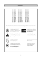
Approvals
Certified to applicable U.S.
standards for appliances using
gas or other petroleum fuel.
Certified to applicable Canadian
standards for appliances using
gas or other petroleum fuel.
Certified by the Uniform
Plumbing Code (UPC)
Certified by National Sanitation
Foundation (NSF), www.nsf.org
(indoor models must use the
NSF approved top guard)
Energy efficiency certified by
Gas Appliance Manufacturers
Association (GAMA),
www.gamanet.org
Met the California Energy
Commission (CEC) standards
Approved by the Commonwealth
of Massachusetts
Received New York City’s
Material and Equipment
Acceptance (MEA)
U
P
C
EFFICIENCY
HEATING
CERTIFIED
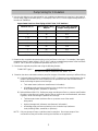
The models listed in this manual have received the following certifications except where noted:
ATI-305-N GTS-305-NI GT-305-NI
ATI-305-P GTS-305-PI GT-305-PI
ATO-305-N GTS-305-NE GT-305-NE
ATO-305-P GTS-305-PE GT-305-PE
ATI-505-N GTS-505-NI GT-505-NI
ATI-505-P GTS-505-PI GT-505-PI
ATO-505-N GTS-505-NE GT-505-NE
ATO-505-P GTS-505-PE GT-505-PE
ATI-705-N GTS-705-NI GT-705-NI
ATI-705-P GTS-705-PI GT-705-PI
ATO-705-N GTS-705-NE GT-705-NE
ATO-705-P GTS-705-PE GT-705-PE
ATI-705A-N GTS-705-NIA AGT-705-NI
ATI-705A-P GTS-705-PIA AGT-705-PI
ATO-705A-N GTS-705-NEA AGT-705-NE
ATO-705A-P GTS-705-PEA AGT-705-PE

4
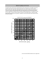
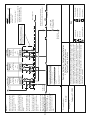
Water Quality and Scale
A complete water analysis and an understanding of system requirements are needed to protect the
tankless water heaters and water heating systems from scale. Water analysis shows whether
water is hard or soft. Hard water, unless treated, will cause scaling or liming of the heat exchanger.
The rate of scaling increases with temperature and usage because calcium carbonate and other
scaling compounds lose solubility (fallout of solution) at higher temperatures. For example, for every
20°F over 140°F, the rate of scale increases by a factor of 2 (See figure below). Reference target
water quality levels found in the operation / installation manual and consider water treatment if these
levels are exceeded. *
210
180
150
120
90
60
30
0
3900
3300
2700
2100
1500
900
300
0
WATER USAGE, gal/day
LIME DEPOSITED, lb/yr
180°F
170°F
160°F
150°F
140°F
120°F
BASED ON 10 grains/gal HARDNESS
*Source 2003 ASHRAE Handbook HVAC Applications
*

5
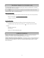
Pump Sizing for Circulation
1. Use the chart below or one appropriate for your conditions to determine the heat loss in the length of
the hot water supply and return piping. For example, 100 ft of 1-1/2 in bare copper tubing results in a
heat loss of 5300 Btu/h.
2. Determine the acceptable temperature drop at the last fixture in the loop. For example, if the supply
temperature from the water heater is 120 ºF (49 ºC) and an acceptable temperature at the last fixture
is 100 ºF (38 ºC) then the acceptable temperature drop is 20 ºF (7 ºC).
3. Calculate the required pump flow rate using the following formula:
FLOW RATE (gpm) = HEAT LOSS (BTU / h)
500 X ACCEPTABLE TEMPERATURE DROP (ºF )
4. Based on the above calculations select a pump for the type of circulation system you will be utilizing:
A). Preferred Method (reference drawing WH-1-RGE) - Reference pump manufacturers flow vs.
pressure specifications to select a pump that can provide the flow rate calculated above
while overcoming the pressure loss through:
• Tank water heater (reference manufacturer’s information)
• All building supply and return plumbing in the circulation loop (reference
local plumbling codes, standards, or practices)
B). Optional Method (WH-1-R) - Reference pump manufacturers flow vs. pressure specifications
to select a pump that can provide 3 gpm of flow or the flow rate calculated above, whichever
is greater, while overcoming the pressure loss through:
• Tankless water heater (reference flow
vs. pressure curve of the model
being used)
• Optional storage tank (reference manufacturer’s information)
• All building supply and return plumbing in the circulation loop (reference
local plumbling codes, standards, or practices)
NOTE: Only use pumps of brass or stainless steel construction. Do not use pumps of iron
construction as they will oxidize and clog the inlet filter on the appliance.
Nominal Size, in. Bare Copper Tubing,
Btu/h-ft
1/2 in. Glass Fiber Insulated
Copper Tubing, Btu/h-ft
7.71 03 4/3
3.02 83 1
4.32 54 4/1-1
4.52 35 2/1-1
6.92 66 2
8.33 08
2/1-2
5.93 49 3
4.84 021 4
Approximate Heat Loss from Piping at 140 ºF Inlet, 70 ºF Ambient *
* Source: 2003 ASHRAE Handbook HVAC Applications

6
Tank Water Heaters in a Circulation Loop
The following applies when using a tank water heater (gas or electric) to provide heat for a circulation
loop. Drawing WH-1-RGE is an example.
The heat output of the tank must be equal to or greater than the calculated circulation loop heat loss.
(Reference page 6, Step 1 on calculating heat loss).
Electric Tank Water Heater
Since the input and output are the same for an electric tank water heater, this can be expressed as:
Electric Tank Input (Kw) >
Circulation loop heat loss (Btu/h)
3413
(1 Kilowatt = 3,413 BTU)
Gas Tank Water Heater
When using a gas style water heater, the efficiency of the tank must be taken into account.
Available Btu output = (Btu input of tank) x (efficiency) >
Circulation loop heat loss (Btu/h)
Example:
30,000 Btu input gas tank
0.62 Efficiency
30,000 x .62 = 18,600 available Btu output
Additional Guidelines
Tankless water heaters not recovering a storage tank: In applications involving a commercial
dishwasher, a hot water circulation loop feeding the dishwasher is required.
Tankless water heater recovering a storage tank: In applications involving a commercial dishwasher, a
hot water circulation loop feeding the dishwasher may be required depending on the distance between
the dishwasher and the storage tank. Refer to local codes when determining the need for circulation
loops to dishwashers.

The following applies when using tankless water heaters to recover a storage tank.
Drawing WH-1-B is an example.
Tankless water heaters have a pressure loss which must be considered in the system design.
Reference the pressure loss curve for the heater model being used to determine the pump size for the
desired recovery rate.
For recommended pump sizes use the table below. Additional pressure losses in plumbing between the
Heater(s) and the storage tank must also be taken into consideration.
The specified pump size is to provide maximum recovery of the storage tank. A smaller pump size may
be used, but could result in longer recovery time of the tank. Please contact the Tech Services department
with any questions on pump sizing.
NOTE: Only use pumps of brass or stainless steel construction. Do not use pumps of iron
construction as they will oxidize and clog
the inlet filter on the appliance.
Pump Sizing for Storage Tank Application
7
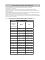
Pump Flow Requirements
Number of
Tankless
Water Heaters
705/505
305
1 6 gpm @ 30' head 5 gpm @ 25' head
2 12 gpm @ 30' head 10 gpm @ 25' head
3 18 gpm @ 30' head 15 gpm @ 25' head
4 24 gpm @ 30' head 20 gpm @ 25' head
5 30 gpm @ 30' head 25 gpm @ 25' head
6 36 gpm @ 30' head 30 gpm @ 25' head
7 42 gpm @ 30' head 35 gpm @ 25' head
8 48 gpm @ 30' head 40 gpm @ 25' head
9 54 gpm @ 30' head 45 gpm @ 25' head
10 60 gpm @ 30' head 50 gpm @ 25' head
11 66 gpm @ 30' head 55 gpm @ 25' head
12 72 gpm @ 30' head 60 gpm @ 25' head
13 78 gpm @ 30' head 65 gpm @ 25' head
14 84 gpm @ 30' head 70 gpm @ 25' head
15 90 gpm @ 30' head 75 gpm @ 25' head

8
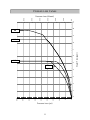
Pressure Loss Curves
Pressure Loss (psi)
Water Flow (gpm)
0.0
5.0
10.0
15.0
20.0
25.0
30.0
35.0
40.0
45.0
01234567891011
0.0
10.0
20.0
30.0
40.0
50.0
60.0
Pressure Loss (ft head)
705
305i
505
305e

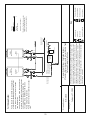
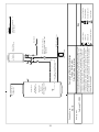
Drawing Number:
Drawing Date:
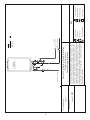
Pressure Relief Valve
3/4" Ball Valve
3/4" Union
Check Valve
Key
S
Pressure Regulator
Circulating Pump
Solenoid Valve
Boiler Drain Valve
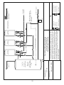
WH-1
Domestic Hot Water - Standard Installation
1 Tankless Water Heater
Preferred Piping Installation
G
a
s
S
u
p
p
ly
3
/
4
"
C
o
l
d
W
a
t
e
r
S
u
p
p
ly
L
in
e
3/4" Hot Water Supply Line
Tankless
Water Heater
Tankless
Equipment List
Tankless
Water Heaters
QTY
1
June 11, 2007
This is not an engineering drawing; it is intended only as a guide and not
as a replacement for professional engineering project drawings. This
drawing is not intended to describe a complete system. It is up to the
contractor or engineer to determine the necessary components and
configuration of the particular system to be installed. The drawing does
not imply compliance with local building code requirements. It is the
responsibility of the engineer or contractor to ensure that the installation is
in accordance with all local building codes. Confer with local building
officials before installation.
9

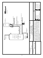
Drawing Number:
Drawing Date:
Pressure Relief Valve
3/4" Ball Valve
3/4" Union
Check Valve
Key
S
Pressure Regulator
Circulating Pump
Solenoid Valve
Boiler Drain Valve
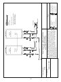
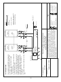
WH-2
Domestic Hot Water - Standard Installation
2 Tankless Water Heaters
Preferred Piping Installation
February 27, 2008
This is not an engineering drawing; it is intended only as a guide and not
as a replacement for professional engineering project drawings. This
drawing is not intended to describe a complete system. It is up to the
contractor or engineer to determine the necessary components and
configuration of the particular system to be installed. The drawing does
not imply compliance with local building code requirements. It is the
responsibility of the engineer or contractor to ensure that the installation is
in accordance with all local building codes. Confer with local building
officials before installation.
Sub 1
Primary
Tankless
Equipment List QTY
Tankless 2
Water Heaters
Electronic Connection *
* Refer to Tankless Accessories
and Model Applicability for
electronic connection details.
10
Cold Water Supply Line
Gas Supply
Hot Water Supply Line
Tankless
Water Heater
Tankless
Water Heater

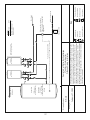
Drawing Number:
Drawing Date:
Pressure Relief Valve
3/4" Ball Valve
3/4" Union
Check Valve
Key
S
Pressure Regulator
Circulating Pump
Solenoid Valve
Boiler Drain Valve
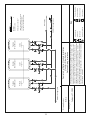
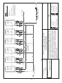
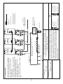
WH-3
Domestic Hot Water - Standard Installation
3 Tankless Water Heaters
Preferred Piping Installation
February 27, 2008
This is not an engineering drawing; it is intended only as a guide and not
as a replacement for professional engineering project drawings. This
drawing is not intended to describe a complete system. It is up to the
contractor or engineer to determine the necessary components and
configuration of the particular system to be installed. The drawing does
not imply compliance with local building code requirements. It is the
responsibility of the engineer or contractor to ensure that the installation is
in accordance with all local building codes. Confer with local building
officials before installation.
Sub 1 Sub 2Primary
11
Cold Water Supply Line
Gas Supply
Tankless
Equipment List QTY
Tankless 3
Water Heaters
Electronic Connection *
* Refer to Tankless Accessories
and Model Applicability for
electronic connection details.
Hot Water Supply Line
Tankless
Water Heater
Tankless
Water Heater
Tankless
Water Heater

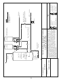
Drawing Number:
Drawing Date:
Pressure Relief Valve
3/4" Ball Valve
3/4" Union
Check Valve
Key
S
Pressure Regulator
Circulating Pump
Solenoid Valve
Boiler Drain Valve
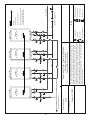
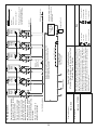
WH-4
Domestic Hot Water - Standard Installation
4 Tankless Water Heaters
Preferred Piping Installation
February 27, 2008
This is not an engineering drawing; it is intended only as a guide and not
as a replacement for professional engineering project drawings. This
drawing is not intended to describe a complete system. It is up to the
contractor or engineer to determine the necessary components and
configuration of the particular system to be installed. The drawing does
not imply compliance with local building code requirements. It is the
responsibility of the engineer or contractor to ensure that the installation is
in accordance with all local building codes. Confer with local building
officials before installation.
Sub 1 Sub 2Primary
Sub 3
12
Tankless
Equipment List QTY
Tankless 4
Water Heaters
Electronic Connection *
* Refer to Tankless Accessories
and Model Applicability for
electronic connection details.
Cold Water Supply Line
Gas Supply
Hot Water Supply Line
Tankless
Water Heater
Tankless
Water Heater
Tankless
Water Heater
Tankless
Water Heater

Drawing Number:
Drawing Date:
Pressure Relief Valve
3/4" Ball Valve
3/4" Union
Check Valve
Key
S
Pressure Regulator
Circulating Pump
Solenoid Valve
Boiler Drain Valve
WH-5
Domestic Hot Water - Standard Installation
5 Tankless Water Heaters
Preferred Piping Installation
February 27, 2008
This is not an engineering drawing; it is intended only as a guide and not
as a replacement for professional engineering project drawings. This
drawing is not intended to describe a complete system. It is up to the
contractor or engineer to determine the necessary components and
configuration of the particular system to be installed. The drawing does
not imply compliance with local building code requirements. It is the
responsibility of the engineer or contractor to ensure that the installation is
in accordance with all local building codes. Confer with local building
officials before installation.
Sub 1 Sub 2Primary Sub 4
Sub 3
13
Cold Water Supply Line
Gas Supply
Hot Water Supply Line
Tankless
Equipment List QTY
Tankless 5
Water Heaters
Electronic Connection *
* Refer to Tankless Accessories
and Model Applicability for
electronic connection details.
Tankless
Water Heater
Tankless
Water Heater
Tankless
Water Heater
Tankless
Water Heater
Tankless
Water Heater

Drawing Number:
Drawing Date:
Pressure Relief Valve
3/4" Ball Valve
3/4" Union
Check Valve
Key
S
Pressure Regulator
Circulating Pump
Solenoid Valve
Boiler Drain Valve
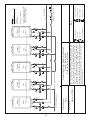
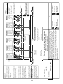
WH-6
Domestic Hot Water - Standard Installation
6 Tankless Water Heaters
Preferred Piping Installation
February 27, 2008
This is not an engineering drawing; it is intended only as a guide and not
as a replacement for professional engineering project drawings. This
drawing is not intended to describe a complete system. It is up to the
contractor or engineer to determine the necessary components and
configuration of the particular system to be installed. The drawing does
not imply compliance with local building code requirements. It is the
responsibility of the engineer or contractor to ensure that the installation is
in accordance with all local building codes. Confer with local building
officials before installation.
Tankless
Water
Heater
Primary
Tankless
Water
Heater
Sub 1
Tankless
Water
Heater
Sub 2
Tankless
Water
Heater
Primary
Tankless
Water
Heater
Sub 1
Tankless
Water
Heater
Sub 2
Pressure Regulator
Set to 5 PSI Below
Street Pressure
14
Cold Water Supply Line
Gas Supply
Tankless
Equipment List QTY
Tankless 6
Water Heaters
Electronic Connection *
* Refer to Tankless Accessories
and Model Applicability for
electronic connection details.
Hot Water Supply Line

Drawing Number:
Drawing Date:
Pressure Relief Valve
3/4" Ball Valve
3/4" Union
Check Valve
Key
S
Pressure Regulator
Circulating Pump
Solenoid Valve
Boiler Drain Valve
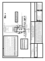
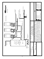
WH-1-D
Domestic Hot Water - Optional Freeze Protection
1 Outdoor Tankless Water Heater
Preferred Piping Installation
June 11, 2007
This is not an engineering drawing; it is intended only as a guide and not
as a replacement for professional engineering project drawings. This
drawing is not intended to describe a complete system. It is up to the
contractor or engineer to determine the necessary components and
configuration of the particular system to be installed. The drawing does
not imply compliance with local building code requirements. It is the
responsibility of the engineer or contractor to ensure that the installation is
in accordance with all local building codes. Confer with local building
officials before installation.
M
i
n
im
u
m
3
/
4
"
C
o
ld
W
a
te
r
S
u
pp
l
y
L
in
e
Minimum 3/4" Hot Water
Supply Line
S
S
1/4" Minimum
Normally Open
SolenoidValve
3/4" Minimum
Normally Closed
Solenoid Valve
Vacuum
Breaker
Tankless
Equipment List
QTY
IMPORTANT!
With electrical power supplied to a Tankless water heater, it will not freeze in
enviornments as cold as -30ºF, when protected from direct wind exposure.
In the event of a power failure at temperatures below freezing, the water
heater should be drained of all water to prevent freezing damage.
The unit may be drained manually or through the installation of the
Optional solenoid valves as shown.
The electrical connections for the two solenoid valves should be tied to
the 120 V power terminals provided on the PC Board of the water heater.
When the electrical power to the water heater fails, the cold water supply
drain down solenoid valve opens, allowing the water heater and
associated piping to drain. Ensure that you run the drain for the solenoids
per local codes.
Outdoor
Tankless
Water Heater
Route drain per local codes
NOTE:
outside building structure. These are indicated
by being above the dashed line.
line should be located inside the building
structure.
The vacuum breaker line should be located inside
the building structure.
NOTE:
enclosure or recess box and packed with insulation
for additional protection.
Outdoor Tankless 1
Water Heater
Gas Supply Line
15

Drawing Number:
Drawing Date:
Pressure Relief Valve
3/4" Ball Valve
3/4" Union
Check Valve
Key
S
Pressure Regulator
Circulating Pump
Solenoid Valve
Boiler Drain Valve
WH-2-D
Domestic Hot Water - Optional Freeze Protection
2 Outdoor Tankless Water Heaters
Preferred Piping Installation
February 27, 2008
This is not an engineering drawing; it is intended only as a guide and not
as a replacement for professional engineering project drawings. This
drawing is not intended to describe a complete system. It is up to the
contractor or engineer to determine the necessary components and
configuration of the particular system to be installed. The drawing does
not imply compliance with local building code requirements. It is the
responsibility of the engineer or contractor to ensure that the installation is
in accordance with all local building codes. Confer with local building
officials before installation.
Hot Water
Supply Line
1/4" Normally Open
Solenoid Valve
Normally Closed
Solenoid Valve
(Full size of supply line)
S
S
Vacuum
Breaker
Sub 1
Primary
IMPORTANT!
With electrical power supplied to a Tankless water heater, it will not freeze in
enviornments as cold as -30ºF, when protected from direct wind exposure.
In the event of a power failure at temperatures below freezing, the water
heater should be drained of all water to prevent freezing damage.
The unit may be drained manually or through the installation of the
Optional solenoid valves as shown.
The electrical connections for the two solenoid valves should be tied to
the 120 V power terminals provided on the PC Board of the water heater.
When the electrical power to the water heater fails, the cold water supply
drain down solenoid valve opens, allowing the water heater and
associated piping to drain. Ensure that you run the drain for the solenoids
per local codes.
NOTE:
outside building structure. These are indicated
by being above the dashed line.
line should be located inside the building
structure.
The vacuum breaker line should be located inside
the building structure.
NOTE:
enclosure or recess box and packed with insulation
for additional protection.
Route drain per local codes
Outdoor
Tankless
Water Heater
Outdoor
Tankless
Water Heater
Cold Water Supply Line
Gas Supply Line
16
Tankless
Equipment List QTY
Tankless Outdood 2
Water Heaters
Electronic Connection *
* Refer to Tankless Accessories
and Model Applicability for
electronic connection details.

Drawing Number:
Drawing Date:
Pressure Relief Valve
3/4" Ball Valve
3/4" Union
Check Valve
Key
S
Pressure Regulator
Circulating Pump
Solenoid Valve
Boiler Drain Valve
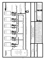
WH-3-D
Domestic Hot Water - Optional Freeze Protection
3 Outdoor Tankless Water Heaters
Preferred Piping Installation
February 27, 2008
This is not an engineering drawing; it is intended only as a guide and not
as a replacement for professional engineering project drawings. This
drawing is not intended to describe a complete system. It is up to the
contractor or engineer to determine the necessary components and
configuration of the particular system to be installed. The drawing does
not imply compliance with local building code requirements. It is the
responsibility of the engineer or contractor to ensure that the installation is
in accordance with all local building codes. Confer with local building
officials before installation.
Hot Water
Supply Line
S
S
Sub 2
Sub 1Primary
Vacuum
Breaker
NOTE:
outside building structure. These are indicated
by being above the dashed line.
line should be located inside the building
structure.
The vacuum breaker line should be located inside
the building structure.
NOTE:
enclosure or recess box and packed with insulation
for additional protection.
Outdoor
Tankless
Water Heater
Outdoor
Tankless
Water Heater
Cold Water Supply Line
Gas Supply Line
Outdoor
Tankless
Water Heater
IMPORTANT!
With electrical power supplied to a
Tankles water heater, it will not
freeze in enviornments as cold as
-30ºF, when protected from direct
wind exposure.
In the event of a power failure at
temperatures below freezing, the
water heater should be drained of
all water to prevent freezing
damage.
The unit may be drained manually
or through the installation of the
Optional solenoid valves as shown.
The electrical connections for the
two solenoid valves should be tied
to the 120 V power terminals
provided on the PC Board of the
water heater.
When the electrical power to the
water heater fails, the cold water
supply solenoid valve closes,
heater, and the drain down
solenoid valve opens, allowing the
water heater and associated piping
to drain. Ensure that you run the
drain for the solenoids per local
codes.
Route drain
per local codes
17
Tankless
Equipment List QTY
Tankless Outdoor 3
Water Heaters
Electronic Connection *
* Refer to Tankless Accessories
and Model Applicability for
electronic connection details.
Normally Closed Solenoid Valve
(Full Size of Cold Water Supply Line)
1/4 “ Minimum
Normally Open
Solenoid Valve

Drawing Number:
Drawing Date:
Pressure Relief Valve
3/4" Ball Valve
3/4" Union
Check Valve
Key
S
Pressure Regulator
Circulating Pump
Solenoid Valve
Boiler Drain Valve
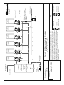
WH-6-D
Domestic Hot Water - Optional Freeze Protection
6 Outdoor Tankless Water Heaters
Preferred Piping Installation
February 27, 2008
This is not an engineering drawing; it is intended only as a guide and not
as a replacement for professional engineering project drawings. This
drawing is not intended to describe a complete system. It is up to the
contractor or engineer to determine the necessary components and
configuration of the particular system to be installed. The drawing does
not imply compliance with local building code requirements. It is the
responsibility of the engineer or contractor to ensure that the installation is
in accordance with all local building codes. Confer with local building
officials before installation.
Vacuum
Breaker
NOTE:
outside building structure. These are indicated
by being above the dashed line.
line should be located inside the building
structure.
The vacuum breaker line should be located inside
the building structure.
NOTE:
a pipe enclosure or recess box and
packed with insulation for additional
protection.
Cold Water Supply Line
Gas Supply Line
IMPORTANT!
With electrical power supplied to a
Tankless water heater, it will not
freeze in enviornments as cold as
-30ºF, when protected from direct
wind exposure.
In the event of a power failure at
temperatures below freezing, the
water heater should be drained of
all water to prevent freezing
damage.
The unit may be drained manually
or through the installation of the
Optional solenoid valves as shown.
The electrical connections for the
two solenoid valves should be tied
to the 120 V power terminals
provided on the PC Board of the
water heater.
When the electrical power to the
water heater fails, the cold water
supply solenoid valve closes,
heater, and the drain down
solenoid valve opens, allowing the
water heater and associated piping
to drain. Ensure that you run the
drain for the solenoids per local
codes.
Route drain
per local codes
Hot Water Supply
S
Sub 2
Sub 1Pri mary
Sub 2Sub 1Pri mary
S
Pressure Regulator
Set to 5 PSI Below
Street Pressure
Outdoor
Tankless
Water Heater
Outdoor
Tankless
Water Heater
Outdoor
Tankless
Water Heater
Outdoor
Tankless
Water Heater
Outdoor
Tankless
Water Heater
Outdoor
Tankless
Water Heater
18
Tankless
Equipment List QTY
Tankless Outdoor 6
Water Heaters
Electronic Connection *
* Refer to Tankless Accessories
and Model Applicability for
electronic connection details.
Normally Closed Solenoid Valve
(Full Size of Cold Water Supply Line)
1/4 “ Minimum
Normally Open
Solenoid Valve

Drawing Number:
Drawing Date:
Pressure Relief Valve
3/4" Ball Valve
3/4" Union
Check Valve
Key
S
Pressure Regulator
Circulating Pump
Solenoid Valve
Boiler Drain Valve
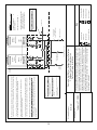
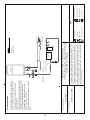
WH-1-RGE
Domestic Hot Water - Circulation Systems
1 Tankless Water Heater with Gas or Electric Tank
Preferred Piping Installation
February 27, 2008
This is not an engineering drawing; it is intended only as a guide and not
as a replacement for professional engineering project drawings. This
drawing is not intended to describe a complete system. It is up to the
contractor or engineer to determine the necessary components and
configuration of the particular system to be installed. The drawing does
not imply compliance with local building code requirements. It is the
responsibility of the engineer or contractor to ensure that the installation is
in accordance with all local building codes. Confer with local building
officials before installation.
Expansion Tank
Minimum 3/4 “ Cold
Water Supply Line
Minimum 3/4 “ Hot
Water Supply Line
Building Supply
Gas Supply Line
Tankless
Water Heater
Important:
Install return line to the hot
supply line as close as possible
to the Tankless water heater
Gas or Electric
Tank Water
Heater
19
For this application:
Pump should be controlled by an Aquastat,
Timer or Combination Aquastat and Timer.
Pump to be sized to maintain circulation
loop temperature.
The pump should be sized to overcome the
pressure loss through the tank water heater,
and supply and return plumbing in the
circulation loop. Reference the section
Pump Sizing for Circulation.
Pump to be of bronze or stainless construc-
tion.
Tankless
Equipment List QTY
Tankless 1
Water Heater

Drawing Number:
Drawing Date:
Pressure Relief Valve
3/4" Ball Valve
3/4" Union
Check Valve
Key
S
Pressure Regulator
Circulating Pump
Solenoid Valve
Boiler Drain Valve
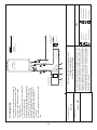
WH-1-R
Domestic Hot Water - Circulation Systems
1 Tankless Water Heater
Optional Piping Installation
June 11, 2007
This is not an engineering drawing; it is intended only as a guide and not
as a replacement for professional engineering project drawings. This
drawing is not intended to describe a complete system. It is up to the
contractor or engineer to determine the necessary components and
configuration of the particular system to be installed. The drawing does
not imply compliance with local building code requirements. It is the
responsibility of the engineer or contractor to ensure that the installation is
in accordance with all local building codes. Confer with local building
officials before installation.
G
a
s
S
u
p
pl
y
(Optional)
2-6 Gallon
Storage Tank
(To eliminate cold water
sandwich e
ect caused by
frequent On/O
operation)
Tankless
Water Heater
Expansion Tank
Minimum 3/4 “ Cold
Water Supply Line
Minimum 3/4 “ Hot
Water Supply Line
Building Outlets
20
For this application:
Pump should be controlled by an Aquastat,
Timer or Combination Aquastat and Timer.
Pump to be sized to maintain circulation
loop temperature.
A minimum of 3 GPM flow is recommended
for the circulation system.
The pump should be sized to overcome the
pressure loss through the Tankless water
heater, optional storage tank, and supply
and return plumbing in the circulation loop.
Reference the section Pump Sizing for
Circulation.
Pump to be of bronze or stainless construc-
tion.
Aquastat Connection
Tankless
Equipment List QTY
Tankless 1
Water Heater
Page is loading ...
Page is loading ...
Page is loading ...
Page is loading ...
Page is loading ...
Page is loading ...
Page is loading ...
Page is loading ...
Page is loading ...
Page is loading ...
Page is loading ...
Page is loading ...
Page is loading ...
Page is loading ...
Page is loading ...
Page is loading ...
-
 1
1
-
 2
2
-
 3
3
-
 4
4
-
 5
5
-
 6
6
-
 7
7
-
 8
8
-
 9
9
-
 10
10
-
 11
11
-
 12
12
-
 13
13
-
 14
14
-
 15
15
-
 16
16
-
 17
17
-
 18
18
-
 19
19
-
 20
20
-
 21
21
-
 22
22
-
 23
23
-
 24
24
-
 25
25
-
 26
26
-
 27
27
-
 28
28
-
 29
29
-
 30
30
-
 31
31
-
 32
32
-
 33
33
-
 34
34
-
 35
35
-
 36
36


American Water Heater GTS-505-PE User manual
- Type
- User manual
Ask a question and I''ll find the answer in the document
Finding information in a document is now easier with AI
Other documents
-
A.O. Smith 505 Series 100 User manual
-
Lochinvar SBN1500 User manual
-
Rinnai Sensei RUR199i Installation guide
-
Rinnai REU-NP3237FF-US-N Installation guide
-
-
Rinnai REU-N2530WC-US-P Operating instructions
-
Rinnai R50LSI User manual
-
Weil-McLain 1194 User manual
-
State Industries 305 Exterior User manual
-
Rinnai CU160EN User manual