Page is loading ...

Instruction / Anleitung
Spannungs-/ Stromsensor F-1678 (150A)
Guarantee / liability exclusion
The company MULTIPLEX Modellsport GmbH & Co.KG accepts no liability of any kind for loss, damage or costs
which are due to the incorrect use and operation of this product, or which are connected with such operation in any
way. Unless the law expressly states otherwise, the liability on the part of MULTIPLEX Modellsport GmbH & Co.KG
to pay damages, regardless of the legal argument employed, is limited to the invoice value of those products supplied
by MULTIPLEX Modellsport GmbH & Co.KG which
CE conformity declaration
This device has been assessed and approved in accordance with European harmonised directives.
This means that you possess a product whose design and construction fulfil the protective aims of
the European Community designed to ensure the safe operation of equipment.
Disposal notes:
Electrical equipment marked with the cancelled waste bin symbol must not be discarded in the standard household
waste; instead it should be taken to a suitable specialist disposal system.
In the countries of the EU (European Union) electrical equipment must not be discarded via the
normal domestic refuse system (WEEE - Waste of Electrical and Electronic Equipment, Directive
2002/96/EG). You can take unwanted equipment to your nearest local authority waste collection
point or recycling centre. There the equipment will be disposed of correctly and at no cost to you.
By returning your unwanted equipment you can make an important contribution to the protection of
the environment!
MULTIPLEX Modellsport GmbH & Co.KG
Westliche Gewerbestr. 1
75015 Bretten - Germany
Multiplex Service: +49 (0) 7252 - 5 80 93 33

Instruction / Anleitung
Spannungs-/ Stromsensor F-1678 (150A)
F1678 – current sensor 150A
# 8 5406
Operating Instructions

Instruction / Anleitung
Spannungs-/ Stromsensor F-1678 (150A)
Dear customer,
We are pleased that you have decided to purchase one of our ROXXY products,
please read the instructions carefully before the installation of the sensor in the fuselage.
Introduction:
The sensor is suitable for use with FASSTest telemetry transmitters or the Telemetry-Box.
Note: Please visit the Futaba website to establish whether a new update is available for your FASSTest- telemetry
transmitter or your Telemetry-Box.
The sensor measures the load current and voltage of the flight / drive battery, potential-free. The current, capacity
and voltage drawn from the battery is also displayed on the screen of the transmitter or the Telemetry-Box.
Specification:
Connecting the sensor:
1.) Unscrew the two screws on the bottom of the case, and remove the circuit board from the case shells.
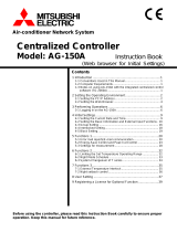
2.) The current sensor is looped in between the drive / flight battery and the speed controller. (A)
The unit can be looped into either the negative or positive wire.
3.) The separated negative or positive wire can be soldered to the lower and / or the upper solder pads.
4.) When soldering the lead, ensure that the end of the conductor is as close as possible to the leg of the shunt
resistor. (B)
Please Note: We recommend a soldering iron of suitable rating (approx. 60 W) to eliminate the danger of dry joints.
For loads below 100 A a conductor with a diameter of at least 4.0 mm² should be soldered to the lower solder pads.
(B)
For loads above 100 A a minimum of two wires with a conductor diameter of at least 4.0 mm² must be soldered to the
lower and upper solder pads. (C / D)
5.) Check that the soldered joints are of good quality.
Voltage- / Currentsensor F-1678 (150 A)
No.
# 8 5406
Voltage range
+5,5 … +65,0 V (2S…14S)
Current range (A)
-150,0 A … +150,0 A
Max. Current (A)
150 A
Resolution (A)
0,1 A
Dimensions (mm)
40 x 30 x 22
Weight (g)
19 g
FASSTest receiver
SBUS2

Instruction / Anleitung
Spannungs-/ Stromsensor F-1678 (150A)
6.) Place the circuit board in the bottom of the case, and place up the top case section for test purposes. If the cable
opening in the case is too small, it can be enlarged using a round file.
7.) When the cable opening in the case is large enough, re-fit the screws to join the case shells again.
8.) The socket marked EXTRA VOLTAGE can be used to send the actual drive / flight battery voltage to the
transmitter automatically. This requires the optional connecting lead with built-in Fuse, Futaba Extra Voltage
Cable (#P-EBB0141). Please take care to maintain correct polarity when completing the connection. A voltage of
up to 65 V DC can be connected to this socket. In the interests of safety the connecting lead incorporates a fuse.
Using the Sensor the first time:
Plug the sensor into the S.BUS2 socket of your telemetry receiver, either directly or via a Y-lead or HUB lead.
The sensor features two sockets, allowing a further S.BUS2 device to be connected to the free socket. The receiver
provides power to the sensor, and also passes the sensor values to the FASSTest transmitter or Telemetry-Box
LED status indicator:
The LED status monitor indicates the following modes:
red LED = Voltage present, but no sensor signals being transmitted
green LED = Voltage present, and sensor signals being transmitted
Resetting the capacity display:
There are 3 methodes of resetting (“zeroing”) the capacity gauge
Mode 1: operating the RESET button while the sensor is active (LED glowing green)
Mode 2: automatic reset after switching on the sensor´s power supply
Mode 3: resetting the capacity via the transmitter
Mode 3 can only be used with FUTABA FASSTest or FASST Multi systems
Therefore you have to assign a switch at switch-channel “DG1”. Operating the switch twice within three seconds
while the sensor is active (LED glowing green) resets the capacity.
Displaying / selecting the modes:
When the sensor is switched on, the LED flashes blue to indicate the actual set mode:
One flash corresponds to Mode 1, two flashes to Mode 2, three flashes to Mode 3.
If you briefly press the reset button during this flashing phase, the sensor remains in display mode, and the indicator
set mode is repeated.
By pressing the RESET button quickly the sensor is scrolling through the modes. Holding the RESET button pressed
confirms the currently indicated mode; the LED then glows green or red.
Calibrating the current display:
The sensor offers a calibration facility. Calibration is may be necessary if the screen displays a current value when no
current is flowing through the sensor. The unit is calibrated by holding the Reset button pressed in: wait until the LED
flashes blue, then wait until the LED has glowed green for two seconds before releasing the button.
/