
Installation Guide
Stacked Thermostatic Valve Trim
K-T10302, K-T10422, K-T10427,
K-T10594, K-T10941, K-T14489,
K-T16176
M product numbers are for Mexico (i.e. K-12345M)
Los números de productos seguidos de
M corresponden a México (Ej.
K-12345M)
Français, page “Français-1”
Español, página “Español-1”
1041504-2-E

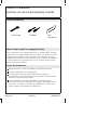
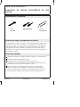
Tools and Materials
Thank You For Choosing Kohler Company
We appreciate your commitment to Kohler quality. Please take a few
minutes to review this manual before you start installation. If you
encounter any installation or performance problems, please don’t
hesitate to contact us. Our phone numbers and website are listed on
the back cover. Thanks again for choosing Kohler Company.
Before You Begin
Observe all local plumbing and building codes.
Shut off the main water supply.
The trim design illustrated in this guide is representative and
may differ from the actual trim being installed. Install the trim as
instructed.
Before installing the trim, determine if the maximum water
temperature is acceptable to the user. If temperature adjustment is
needed, refer to the instructions packed with your valve for
proper temperature limiting adjustment.
Kohler Co. reserves the right to make revisions in the design of
products without notice, as specified in the price book.
Screwdrivers
Hex
Wrenches
Adjustable
Wrench
1041504-2-E 2 Kohler Co.

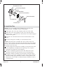
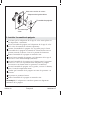
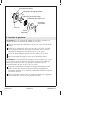
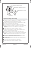
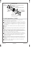
1. Install the Valve Stem Adapter
IMPORTANT! Two screws of each length are supplied for this step,
one metric and one standard. If the screw you are using is difficult
to thread into the opening, remove it and use the other screw.
NOTE: Check the finished wall surface as related to the graphics on
the plaster guard.
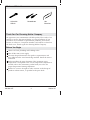
Select the correct length valve stem adapter and valve stem
adapter screw for your application. Refer to the information
stamped on the plaster guard to verify the wall thickness.
For a thin wall - 3/16″ (5 mm) to 9/16″ (1.4 cm): use the 7/8″ (2.2
cm) (short size) valve stem adapter, stamped ″3″ on the plaster
guard. Use the 3/4″ (1.9 cm) screw for the top valve and the 1-3/8″
(3.5 cm) screw for the lower valve.
For a standard wall - 9/16″ (1.4 cm) to 1-1/16″ (2.7 cm): use the
1-3/8″ (3.5 cm) (middle size) valve stem adapter, stamped ″1″ on the
plaster guard. Use the 1-3/8″ (3.5 cm) screw for the top valve and
the 1-3/4″ (4.4 cm) screw for the lower valve.
For a thick wall - 1-1/16″ (2.7 cm) to 1-9/16″ (4 cm): use the 1-7/8″
(4.8 cm) (long size) valve stem adapter, stamped ″2″ on the plaster
guard. Use the 1-3/4″ (4.4 cm) screw for the top valve and the
2-3/8″ (6 cm) screw for the lower valve.
Remove and discard the plaster guard from the valve.
Select the correct
valve stem adapter.
Remove and discard
the plaster guard.
Valve Stem
Adapter
Spline
Adapter
Finished
Wall
Kohler Co. 3 1041504-2-E

Install the Valve Stem Adapter (cont.)
Place the spline adapters over the valve stems.
Set the correct valve stem adapters over each valve stem. Do not
completely press or screw the valve stem adapters into place
until instructed to do so.
1041504-2-E 4 Kohler Co.

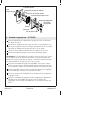
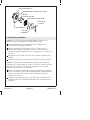
2. Adjust the Handle Assembly
Ensure the valve stem adapters are lightly placed over the spline
adapters.
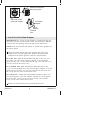
Place the handle assembly over the valve stem adapter of the
volume control valve (top).
Turn the handle assembly counterclockwise until it stops. The
volume control handle assembly should be in the vertical 12
o’clock position. This is the off position.
Remove the handle assembly and set aside.
Place the remaining handle assembly over the valve stem adapter
of the thermostatic valve (bottom).
Turn the handle assembly clockwise until the stop is contacted.
The valve will be in the full cold position. The handle should be
between the 9 and 10 o’clock positions.
Rotate the handle assembly counterclockwise, through the detent,
then to the high temperature limit stop.
Verify that the handle assembly is between the 3 and 4 o’clock
position.
Rotate back to 6 o’clock position.
Remove the handle assembly and set aside.
NOTE: The spline adapter allows fine adjustment of the handle
alignment.
Valve Stem Adapter
Handle Assemblies
Thermostatic
Valve
Volume Control Valve
Kohler Co. 5 1041504-2-E

Adjust the Handle Assembly (cont.)
To adjust, remove the handle assembly and the valve stem
adapter.
Reposition the spline adapter.
Reinstall the handle assembly and the valve stem adapter.
Check the alignment.
Repeat until the handle alignment is satisfactory.
1041504-2-E 6 Kohler Co.

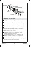
3. Install the Trim
NOTE: If you are installing the K-T10422 trim, proceed to the
″Install the Trim - K-T10422″ section of this guide.
Firmly press the valve stem adapters onto each valve stem.
Secure the valve stem adapters to the valve with the correct
length screws, as selected in the ″Install the Valve Stem Adapters″
section of this guide.
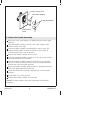
Thread the two threaded studs into the threaded holes of the
valve.
Place the front plate assembly over the threaded studs.
NOTE: If the front plate assembly does not lay flat on the wall
surface, loosen the nuts and adjust the threaded studs, then tighten
the nuts. The maximum distance between the threaded studs from
the wall is 7/16″ (1.11 cm).
Visually inspect the front plate assembly to ensure that the foam
seal is completely covering the wall opening. If not, stop the
installation and repair the wall opening.
Place the escutcheon against the wall. The drain hole in the
escutcheon should face downward in the 6 o’clock position.
Thread the handle assemblies onto the hubs of the front plate
assembly to secure the escutcheon in place. The volume control
handle assembly (top) should be at the 12 o’clock position. The
thermostatic valve handle assembly (bottom) should be at the 6
o’clock position.
Thermostatic Valve
Valve Stem Adapter
Finished Wall
Front Plate Assembly
Escutcheon
Screws
Threaded Studs
Nuts
Handle Assembly
Kohler Co. 7 1041504-2-E

Install the Trim (cont.)
NOTE: If the handle does not engage the valve or the escutcheon
does not tighten to the wall, replace the valve stem adapter with an
adapter of appropriate length.
1041504-2-E 8 Kohler Co.

4. Install the Trim - K-T10422
Firmly press the valve stem adapters onto each of the valve
stems.
Secure the valve stem adapters to the valve stem with the correct
length screws, as selected in the ″Install the Valve Stem Adapters″
section of this guide.
Thread the two threaded studs into the threaded holes of the
valve.
Place the front plate assembly over the threaded studs.
NOTE: If the front plate assembly does not lay flat on the wall
surface, loosen the nuts and adjust the threaded studs, then
re-tighten the nuts. The maximum distance between the threaded
studs from the wall is 7/16″ (1.11 cm).
Inspect the front seal plate assembly to ensure that the foam seal
is completely covering the wall opening. If not, stop the
installation and repair the wall opening.
Place the escutcheon against the wall. The drain hole in the
escutcheon should face downward in the 6 o’clock position.
Thread the adapter rings onto the hub of the front plate assembly.
Place the handle assemblies against the escutcheon by lining up
the pins in the handle assembly with the holes in the escutcheon.
Make sure the setscrew holes are facing down.
Valve Stem Adapter
Adapter Ring
Volume Control
Setscrews
Escutcheon
Thermostatic
Valve
Screw
Screw
Front Plate Assembly
Threaded Studs
Nuts
Handle
Assembly
Kohler Co. 9 1041504-2-E

Install the Trim - K-T10422 (cont.)
NOTE: The volume control handle should be at the 12 o’clock
position. The thermostatic valve handle should be at the 6 o’clock
position.
Tighten the setscrews in place with a hex wrench. Make sure the
handle assemblies are tight against the escutcheon.
1041504-2-E 10 Kohler Co.
Page is loading ...
Page is loading ...
Page is loading ...
Page is loading ...
Page is loading ...
Page is loading ...
Page is loading ...
Page is loading ...
Page is loading ...
Page is loading ...
Page is loading ...
Page is loading ...
Page is loading ...
Page is loading ...
Page is loading ...
Page is loading ...
Page is loading ...
Page is loading ...
Page is loading ...
Page is loading ...
Page is loading ...
Page is loading ...
-
 1
1
-
 2
2
-
 3
3
-
 4
4
-
 5
5
-
 6
6
-
 7
7
-
 8
8
-
 9
9
-
 10
10
-
 11
11
-
 12
12
-
 13
13
-
 14
14
-
 15
15
-
 16
16
-
 17
17
-
 18
18
-
 19
19
-
 20
20
-
 21
21
-
 22
22
-
 23
23
-
 24
24
-
 25
25
-
 26
26
-
 27
27
-
 28
28
-
 29
29
-
 30
30
-
 31
31
-
 32
32


Kohler K-T10941-4-BN Installation guide
- Type
- Installation guide
- This manual is also suitable for
Ask a question and I''ll find the answer in the document
Finding information in a document is now easier with AI
in other languages
Related papers
-
Kohler K-T10594-4P-BN Installation guide
-
Kohler T10069-9-BN Installation guide
-
-
Kohler K-T72769-9M-CP Installation guide
-
-
Kohler T13175-4A-SN Installation guide
-
-
-
-
Kohler K-TLS10582-4-CP User manual
