Page is loading ...

CENTRALE DI COMANDO
CONTROL UNIT
STEUEREINHEIT
CENTRALE DE COMMANDE
CENTRAL DE MANDO
CENTRALKA STEROWANIA
L8542108
Rev. 02/06/02
Libro istruzioni
Operating instructions
Betriebsanleitung
Livret d’instructions
Manual de instrucciones
Książeczka z instrukcjami
UNIONE NAZIONALE COSTRUTTORI
AUTOMATISMI PER CANCELLI, PORTE,
SERRANDE ED AFFINI

3
Dichiarazione CE di conformità Déclaration CE de conformité
EC declaration of conrmity Declaracion CE de conformidad
EG-Konformitatserklarung
Deklaracja UE o zgodności
Con la presente dichiariamo che il nostro prodotto
We hereby declare that our product
Hiermit erklaren wir, dass unser Produkt
Nous déclarons par la présente que notre produit
Por la presente declaramos que nuestro producto
Niniejszym oświadczamy że nasz produkt
BRAIN 24
è conforme alle seguenti disposizioni pertinenti:
complies with the following relevant provisions:
folgenden einschlagigen Bestimmungen entspricht:
correspond aux dispositions pertinentes suivantes:
satisface las disposiciones pertinentes siguientes:
zgodny jest z poniżej wyszczególnionymi rozporządzeniami:
Direttiva sulla compatibilità elettromagnetica
(89/336/CCE, 93/68/CEE)
EMC guidelines (89/336/EEC, 93/68/EEC)
EMV-Richtlinie (89/336/EWG, 93/68/EWG)
Directive EMV (89/336/CCE, 93/68/CEE)
(Compatibilité électromagnétique)
Reglamento de compatibilidad electromagnética
(89/336/MCE, 93/68/MCE)
Wytyczna odnośnie zdolności współdziałania elektromagne-
tycznego (89/336/EWG, 93/68/EWG)
Benincà Luigi, Responsabile legale.
Sandrigo, 05/10/2005.
Direttiva sulla bassa tensione (73/23/CEE, 93/68/CEE)
Low voltage guidelines (73/23/EEC, 93/68/EEC)
Tiefe Spannung Richtlinie (73/23/EWG, 93/68/EWG)
Directive bas voltage (73/23/CEE, 93/68/CEE)
Reglamento de bajo Voltaje (73/23/MCE, 93/68/MCE)
Wytyczna odnośnie niskiego napięcia (73/23/EWG,
93/68/EWG)
Automatismi Benincà SpA
Via Capitello, 45
36066 Sandrigo (VI)
ITALIA

3
24Vac/24Vdc
SHIELD
ANT
ANT
M1
M2
LAMP
24Vdc
Lock 12Vac
10W (5s)
24Vac/dc
500mA max
(+) (-)
SWO1
SWC1
SWO2
SWC2
PHOT
PHOTC
STOP
OPEN
CLOSE
PED
P.P.
COM
COM
RADIO
F1
T 2A
LED
DAS
J1 DAS
Open
DAS N.C.
J1 DAS
Close
DAS 8K2
2726
1
2
3
4
5
6
7
8
9
10
11
12
13
14
15
16
17
18
19
20
21
22
23
24
25
2726
8k2
DAS
3130
+-
SCA 24Vac
3W ma
x
9
8
10
11
12
13
2ch:Off
2ch:On
9
8
10
11
90s
SERL:On
9
8
10
7
6
L N
11
12
13
Service
Light
230V

4
5
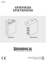
Collegamento scheda CB.24V (opzionale)
Connection to the CB.24V Card (optional)
Anschluss Karte CB.24V (Option)
Branchement fiche CB.24V (optionnel)
Conexión tarjeta CB.24V (opcional)
Połączenie karty CB.24V (opcjonalna)

10
11
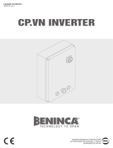
BRAIN 24 control unit
The BRAIN 24 electronic control unit may be used for the control of 1 or 2 motors 24Vdc with power not higher than 80W+80W.
GENERAL WARNINGS
a) The electrical installation and the operating logic must comply with the regulations in force.
b) The leads fed with different voltages must be physically separate, or they must be suitably insulated with additional insulation of
at least 1 mm.
c) The leads must be secured with an additional fixture near the terminals.
d) Check all the connections again before switching on the power.
e) The unused N.C. inputs must be bridged.
INPUT/OUTPUT FUNCTIONS
BRAIN 24 Control unit
Terminal No. Function Description
1-2 Motor 1 Connection, motor 1: 24VDC 80W max
3-4 Motor 2 Connection, motor 2: 24VDC 80W max
5-6 Flashing light Connection, flashing light 24VDC 15W max.
7-8 Lock Output, 12VAC/10W (5s) power supply for electric lock (7:0V, 8:+12V)
9-10 SCA/2°Ch radio
Normally open clean contact. Controlled by “2Ch” logic.
With 2ch logic Off: SCA contact, open gate indicator.
With 2ch logic On: Contact controlled by 2
nd
radio channel of the receiver.
Note: with “SRL” logic On, it performs the contact function of the courtesy light control, see
table of logic.
11-12 24 Vac/dc
Output, accessory power supply, 24VAC/0.5A max.
IMPORTANT: If the battery charger board CB.24V is installed, the output (without mains power
connected) has a 24Vdc polarised voltage.
Make sure the devices are correctly connected (i.e. 11:+24Vdc / 12:-24Vdc).
13 COM Common for limit switches and all control inputs.
14 SWO1 Input, OPEN limit switch, motor 1 (Normally closed contact)
15 SWC1 Input, CLOSE limit switch, motor 1 (Normally closed contact)
16 SWO2 Input, OPEN limit switch, motor 2 (Normally closed contact)
17 SWC2 Input, CLOSE limit switch, motor 2 (Normally closed contact)
18 PHOT Input, photocell activated in both opening and closing phases
19 PHOT C Input, photocell activated in closing phase only
20 STOP Input, STOP push-button (Normally closed contact)
21 OPEN Input, OPEN push-button (Normally open contact).
22 CLOSE Input, CLOSE push-button (Normally open contact)
23 PED
Input, push-button for pedestrian use (Normally open contact), it controls the complete
opening of motor 1
24 Step-by-Step Input, step-by-step push button (Normally open contact)
25 COM Common for all control inputs.
26-27 BAR
Input, sensitive edge contact
Resistive edge: “DAS” Jumper closed
Mechanical edge: “DAS” Jumper open
When the edge is activated, the gate movement is stopped and reversed for about 3s.
30-31 Antenna Connection to the insertable radio receiver card (30-signal/31-screen).
JF1-JF2 24VAC/dc
Input, 24VAC/24VDC power supply.
If buffer batteries are used, connect the CB.24V card (in option) as indicated in the table.
Programming
The programming of the various functions of the control unit is carried out using the LCD display on the control unit and setting
the desired values in the programming menus described below.
The parameters menu allows you to assign a numerical value to a function, in the same way as a regulating trimmer.

10
11
The logic menu allows you to activate or deactivate a function, in the same way as setting a dip-switch.
Other special functions follow the parameters and logic menus and may vary depending on the type of control unit or the software
release.
To access programming:
1 – Press the button <PG>, the display goes to the first menu, Parameters “PAR”.
2 – With the <+> or <-> button, select the menu you want (PAR>>LOG>>RADIO>>NMAN>>RES>>PAR>>....).
3- Press the button <PG>, the display shows the first function available on the menu.
4 - With the <+> or <-> button, select the function you want.
5 - Press the button <PG>, the display shows the value currently set for the function selected.
6 - With the <+> or <-> button, select the value you intend to assign to the function.
7 - Press the button <PG>, the display shows the signal “PRG” which indicates that programming has been completed.
Notes:
Simultaneously pressing <+> and <-> from inside a function menu allows you to return to the previous menu without making any
changes.
Simultaneously pressing <+> and <-> when the display is switched off shows the card software release.
Hold down the <+> key or the <-> key to accelerate the increase/decrease of the values.
After waiting 60s the control unit quits programming mode and switches off the display.
Parameters, Logic and Special Functions
The tables below describe the individual functions available in the control unit.
MENU FUNCTION
Settable values
MIN-MAX-(Default)
MEMO
PARAMETERS
TCA
Automatic closing time. Active only with logic “TCA”=ON.
At the end of the set time the control unit orders a closing manoeuvre.
1-240-(40s)
TM1
Operating time, motor 1. The operating time is adjusted at normal speed
during motor 1 opening and closing phases. See section “Adjustment of
braking”.
5-180-(8s)
TM2
Operating time, motor 2. The operating time is adjusted at normal speed
during motor 2 opening and closing phases. See section “Adjustment of
braking”.
5-180-(8s)
PMo1
The torque applied to motor 1 during the opening phase is adjusted.* 1-99-(50%)
PMC1
The torque applied to motor 1 during the closing phase is adjusted.* 1-99-(50%)
PMo2
The torque applied to motor 2 during the opening phase is adjusted.* 1-99-(50%)
PMc2
The torque applied to motor 2 during the closing phase is adjusted.* 1-99-(50%)
TDMo
Mot.2 opening delay time.
Regulates the delay time of motor 2 on opening with respect to motor 1
0-15-(2s)
TDMC
Mot.1 closing delay time
Regulates the delay time of motor 1 on closing with respect to motor 2
0-40-(3s)
TLOc
Electric lock activation time. If the electric lock is not used, set the param-
eter at 0.
0-5-(3s)
SLDS
The motor speed during braking is adjusted. The value is expressed in per-
centage with respect to speed during normal operation.
30-99 (50)
Pso1
The torque applied to motor 1 during braking in the opening phase is ad-
justed *
1-99-(50%)
Psc1
The torque applied to motor 1 during braking in the closing phase is ad-
justed *
1-99-(50%)
Pso2
The torque applied to motor 2 during braking in the opening phase is ad-
justed *
1-99-(50%)
Psc2
The torque applied to motor 2 during braking in the closing phase is ad-
justed *
1-99-(50%)
* WARNING: An incorrect setting of these parameters may result in an hazard. Comply with regulations in force!
Adjustment of braking
With braking enabled (SLD logic: ON), braking will start at end of time preset with TM1 and TM2.
The preset time should therefore be lower than the real stroke of the operator. For example, with a 20s stroke, preset 17s to start
the braking phase, 3s in advance with respect to end of movement.
Note: The TM1 and TM2 parameters do not work with braking disabled (SLD logic: OFF), as the end of operation is determined

12
13
only by the triggering of the limit switch or by the amperometric sensor. The speed of the motor during braking is determined by
the SLDS parameter value.
MENU FUNCTION
Settable values
ON-OFF-(Default)
MEMO
LOGIC
TCA
Enables or disables automatic closing
On: automatic closing enabled
Off: automatic closing disabled
(ON)
IbL
Enables or disables condominium function.
On: condominium function enabled. The step-by-step impulse or
transmitter impulse has no effect during the opening phase.
Off: condominium function disabled.
(OFF)
SCL
Enables or disables rapid closing
On: rapid closing enabled. With the gate open or in the opening
phase the intervention of the photocell causes automatic closing
after 3 s. Active only with TCA:ON.
Off: rapid closing disabled.
(OFF)
Sld
Enables or disables slowing.
On: Slowing active.
Off: Slowing excluded.
(OFF)
PP
Selects the operating mode of the ”Step by step button” and of the
transmitter.
On: Operation: OPEN > CLOSE > OPEN >
Off: Operation: OPEN > STOP > CLOSE > STOP >
(OFF)
PRE
Enables or disables pre-blinking.
On: Pre-blinking enabled. Blinking is activated 3s before the motor
starts.
Off: Pre-blinking disabled.
(OFF)
Blc
The lock function is enabled or disabled.
On: Lock function enabled. After the activation of closure limit switch-
es the control unit delays the stop by approx. 0.5s in order to allow a
better resting of the gate against the stoppers.
Off: Lock function disabled.
(ON)
CLOC
Selects the mode of the OPEN input
On: OPEN input with CLOCK function.
To be used for connection to a timer for timed opening/closing. (Con-
tact CLOSED- gate open, Contact open, normal operation).
Off: OPEN input with OPEN function
(OFF)
htr
Enables or disables Man present function.
On: Man Present operation.
The OPEN/CLOSE buttons must be held down during the whole
manoeuvre.
Off: Automatic operation.
(OFF)
mloc
Selects the type of electric lock used.
On: Magnetic electric lock, normally fed at 12Vac/O,5A max.
Before each opening manoeuvre the power supply is interrupted for
the time set by the parameter TLOC.
Off: Electric lock with latch, normally not fed.
Before each opening manoeuvre power is fed at 12Vac for the time
set by the parameter TLOC.
(OFF)
1mot
Select the 1/2 motors operating mode:
On: Only motor 1 operating.
Off: Both motors operating.
(OFF)

12
13
MENU FUNCTION
Settable values
ON-OFF-(Default)
MEMO
LOGIC
Cvar
The code programmable transmitters is enabled or disabled.
On: Radio receiver enabled only for rolling-code transmitters.
Off: Receiver enabled for rolling-code and programmable code
transmitters (self-learning and Dip Switch).
OFF
NOlS
The operation mode of the amperometric sensor is selected ei-
ther the limit switches are provided or not.
On: Limit switches not provided. The amperometric sensor
activation is interpreted by the control unit as limit switch. The
control signal is sent to stop the movement. Note: To use this
function, close the limit switch contacts with jumpers. The “SLD”
Logic should be positioned to OFF
Off: Limit switches provided. The amperometric sensor activation
is interpreted by the control unit as obstacle present in the gate
movement area. Similarly to the safety edge activation, the con-
trol signal is sent to stop and reverse movement for approx. 3s.
(OFF)
2Ch
The output performance at Terminals 9-10:
On: The output has the function of 2
nd
radio channel: the nor-
mally open contact switches for 1s at reception of a radio control
assigned to the 2
nd
radio channel. See radio menu.
Off: The output has the SCA function, open gate LED: open
contact with closed gate, flashing light during gate movement,
closed contact with open gate. See wire diagram.
(OFF)
serL
Service light function is enabled or disabled on output 9-10.
On: at each movement, the contact is closed for approx. 90s,
regardless of the configuration of 2ch parameter.
For the light control use the auxiliary relay.
Off: The performance of the output is preset by 2ch parameter,
see previous parameter.
(OFF)
MENU FUNCTION
RADIO
PP
By selecting this function, the receiver awaits (Push) for a transmitter code to be assigned to the step-
by-step function.
Press the transmitter key to be assigned to this function.
If the code is valid, it is stored in memory and OK appears.
If the code is not valid, the wording Err is displayed.
2ch
By selecting this function, the receiver awaits (Push) for a transmitter code to be assigned to the second
radio channel, on Terminals 9-10.
The 2ch logic must be ON, the SERL logic must be OFF.
Press the transmitter key to be assigned to this function.
If the code is valid, it is stored in memory and OK appears.
If the code is not valid, the wording Err is displayed.
CLr
By selecting this function, the receiver awaits (Push) for a transmitter code to be erased from memory.
If the code is valid, it is erase and OK appears.
If the code is not valid or is not in memory, the wording Err is displayed.
RTR
Completely erase the receiver memory. Confirmation of operation is required.
MENU FUNCTION
NMAN
Displays the number of complete cycles (open+close) carried out by the automation.
When the <PG> button is pressed for the first time, it displays the first 4 figures, the second time it shows the
last 4. Example <PG> 0012 >>> <PG> 3456: made 123.456 cycles.
RES
RESET of the control unit. ATTENTION!: Returns the control unit to the default values.
Pressing the <PG> button for the first time causes blinking of the letters RES, pressing the <PG> button again
resets the control unit.
Note: The transmitter codes are not erased from the receiver.
Example of programming
Let us suppose it is necessary to:
- set an automatic closing time (TCA) of 100s
- activate pre-blinking
Perform the operations described below step by step:

14
15
Step Press Display Notes
1
PAR
First menu
2
TCA
First function of the first menu
3
040
Value currently set for the function selected
4
100
Set the desired value with the <+> and <-> keys
5
PRG
The value is programmed
TCA
When programming has been made, the display goes to the function just set
6
PAR
Press <+> and <-> simultaneously to go to the higher menu
7
Log
Second menu
8
TCA
First function of the second menu
9
Pre
Press <-> several times to select PRE logic
10
OFF
Value currently set for the function selected
11
ON
Set the desired value with the <+> and <-> keys
12
PRG
The value is programmed
Pre
When programming has been made, the display goes to the function just set
13
PAR
Press <+> and <-> simultaneously to go to the higher menu and quit programming or
wait 30s.
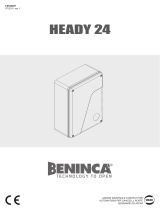
Diagnostics
In the event of malfunctions, by pressing key + or - the status of all inputs (limit switches, control and safety) can be displayed. One
segment of the display is linked to each input. In the event of failure it switches on according to the following scheme.
N.C. inputs are represented by the vertical segments. N.O. inputs are represented by the horizontal segments.
For example, with the leaves
completely closed the display
is as follows:
the moment an Open impulse
is given:
during the opening phase: with the leaves completely
open:
/