
STEP 3. Remove loader.
STEP 4. Turn marker upside down to remove paintballs from feed port.
STEP 5. Remove barrel.
STEP 6. Point marker toward ground in a safe direction and fire several
times to insure it is completely unloaded. Put marker back on safe.
STEP 7. Remove gas source.
STEP 8. Use squeegee to dislodge any paintballs from barrel and replace
barrel plug.
STEP 9. Replace barrel. Do not unload your marker indoors.
WARNING: Do not look down the breach or barrel of the marker
while gas source is attached.
SPECIAL INSTRUCTIONS
Maintenance/Operation
Follow all procedures listed in this manual. In addition, periodically check
the steel braided hose assembly for leaks or fraying.
Safety
Do not allow the steel braided hose to be pinched in any way. The hose is
durable but is not intended to act as a trigger guard.
E-GRIP OPERATION
NOTE: Marker will not cock or field strip with safety in the ON position.
STEP 1. EYE PROTECTION:
Make sure everyone within range
(200 yards) is properly protected
from paintball impacts.
STEP 2. PUT ON “SAFE.”
Push safety from left to right; no
red band showing. Make sure
barrel plug is placed securely in
muzzle of marker.
STEP 3. INSTALL BATTERY:
Remove grip cover and install 9
volt battery (High performance
type recommended) into grip
after connecting battery clip
(See Fig. B).
STEP 4. TEST: Test for power
before installing grip cover.
STEP 5. TURN ON: Turn grip
on by depressing ON/OFF button
for 3 seconds until red light is show-
ing. Depress again until red light
turns green (See Fig. C). Depress
trigger and watch for solenoid
function.
STEP 6. REPLACE GRIP COVER
(Don’t overtighten screws).
STEP 7. TEST FIRE: Following
the operation instructions below,
first test fire the marker without
paint.
NOTE: Should marker develop
function problems related to the grip,
replace the battery with a new 9 volt high output, high performance
battery before any other trouble shooting mesures.
STEP 8. SWITCH FIRING MODES: To switch between the different
modes, first turn the e-grip on. The marker will be in Semi-Auto mode
(Green Top LED light). Press the on/off button once for 3-shot burst mode
(Orange Top LED light). Press the on/off button again for Full Auto mode
(Red Top LED light). Press the button again to return back to Semi-Auto
mode.
STEP 9. TURN OFF: To turn off marker, depress ON/OFF button 3
seconds or longer.
STEP 10. LOW BATTERY LIGHT: The bottom LED light is a low bat-
tery indicator. Green indicates good battery. Red indicates a low battery;
replace the battery for the marker to perform correctly.
NOTE: For best performance of the marker use an electronic loader
Revolution, CAT, Evolution 3 or VLocity loader. Insure you are using robust
paintballs for 3 round burst and full automatic modes to avoid excessive
paintball breakage.
OPERATING INSTRUCTIONS
WARNING: Be sure the paintball marker is always pointed in a safe
direction. Read the following operating instructions and WITHOUT LOADING
ANY PAINTBALLS proceed several times through the operating steps with
your paintball marker (dry fire the paintball marker at a safe target) so that
you will be able to operate the marker properly and safely.
STEP 1. EYE PROTECTION: Make sure everyone within range (200
yards) is properly protected from paintball impacts.
STEP 2. Take marker off safe, for cocking with top cocking pin.
STEP 3. COCK: Cock marker by pulling cocking handle fully back until
locked in sear position. This marker is a semi-automatic marker, which will
re-cock itself after firing when working properly.
STEP 4. PUT ON “SAFE”. Push safety from left to right; no red band
showing. Make sure barrel plug is placed securely in muzzle of marker.
STEP 5. ATTACH GAS SOURCE: Marker can be used with a Brass
Eagle® constant air refillable cylinder (not included). You should expect
better gas efficiency with a larger refillable cylinder. (RECOMMEND Brass
Eagle® 9oz. refillable cylinder. Item #1471.)
NOTE: Add 3 drops of mineral oil to the ASA adapter prior to
attaching the refillable cylinder. Check the website at:
www.Strykerpaintball.com for approved lubricants.
STEP 6. LOAD PAINTBALLS:
A) Insert loader (not included with all packaging) into ball feed port. Grip
loader from the top. Insert loader feed neck into ball feed port on the
marker. Twist and push firmly in a clockwise direction.
NOTE: The loader to ball feed port fit is purposely tight. (RECOMMEND
Viewloader
®
Quantum
TM
, eVLution II
TM
or Revolution
TM
electronic loader)
B) Pour paintballs into loader. NOTE:
Paintballs are gravity fed from loader to
the marker each time the trigger is pulled.
Too rapid a rate of fire, broken balls or too
many balls in loader may cause subsequent
balls to break and will adversely affect the
paintball marker’s accuracy. Use a squeegee
to clean inside the paintball marker’s bar-
rel. (RECOMMEND Stryker™, Brass Eagle
®
,
Viewloader
®
,JT
®
, or WGP
®
brand .68 caliber
paintballs.) Paintballs should be stored in a
cool, dry place in sealed plastic bags. Do not
subject to freezing, excessive heat, humidity
or store in direct sunlight. These conditions
may cause ball breakage and/or poor feed-
ing.
STEP 7. Turn on E-Grip per operation
instructions to semi-automatic mode (dual
green led lights).
STEP 8. Remove barrel plug and take off
safe by pressing safety from right side of
paintball marker until red band is showing.
STEP 9. FIRE: Paintball marker is now
ready to fire.
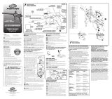
STEP 10. VERIFY VELOCITY: Verify that the paintball marker’s
velocity is below 300 feet per second or less if required by playing field.
Velocity should be measured with a chronograph prior to playing paint-
ball. Velocity may be adjusted by turning the velocity adjustment screw
(See Fig. A) Using a 1/8” allen key (included) turn the screw clockwise to
increase velocity and counter-clockwise to decrease velocity. (RECOMMEND
Viewloader® on-barrel chronograph to verify velocity. Item #7815.) NOTE:
Additional velocity adjustment available by
adding or removing hammer spring spacer. (Fig. B)
WARNING: Never shoot at anyone without proper
protective equipment for eyes, which must be worn at all times. Eye protec-
tion must be designed specifically for paintball use. Failure to follow these
safety precautions may result in bodily injury including blindness and deaf-
ness.
UNLOADING YOUR MARKER
WARNING: Always wear proper eye, face and
ear protection designed especially to stop paintballs while unloading your
paintball marker.
STEP 1. Make sure barrel plug is securely in barrel.
STEP 2. Put Marker on safe. (Push left to right)
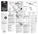
FIELD STRIP GUIDE
Bolt and Striker removal
STEP 1. EYE PROTECTION: Make sure everyone within range (200
yards) is properly protected from paintball impacts.
STEP 2. Remove gas supply from marker.
STEP 3. Make sure cocking bolt is in the forward position. Pull trigger to
release if necessary.
STEP 4. Remove Quick Pull Pin and Remove Velocity Plug, Bumper,
Spring Guide, Spacer, and Spring Hammer and Bolt (Figure B). NOTE: Use
caution when removing as all parts are under spring tension.
FIELD STRIP REASSEMBLY
Follow the steps above in reverse order. Lubricate all wear points and
o-rings with minerial oil only.
HAMMER REMOVAL / REPLACEMENT
STEP 1. Follow Steps 1-5 of Field Strip Guide.
STEP 2. Pull trigger and tap rear of the reciever against towel on flat
surface to remove hammer.
STEP 3. Grasp hammer with fingers and pull from receiver.
STEP 4.
Clean with soft cloth or baby wipe. Relubricate with mineral oil
and replace. NOTE: Examine o-ring for any damage and replace if neces-
sary.
STEP 5. Step 5. Turn E-grip on, make sure safety is in the off position
then follow step 6.
STEP 6. Replace hammer bolt assembly into receiver with sear flat down.
NOTE: It is necessary to pull the trigger 3 or more times while applying
pressure to striker bolt assembly with your finger in order to fully seat the
hammer. (See Figure C)
STEP 7. Reassemble per Field Strip Reassembly Section.
DISASSEMBLY / CLEANING OF BALL
DETENT
STEP 1. Remove 2 phillips head screws.
STEP 2. Remove ball detent and cover.
Figure B
VELOCITY PLUG
Taco de Velocidad
Obturateur de Vitesse
SPRING
Resorte
Ressort
SPRING GUIDE
Guia De Resorte
Guide-Ressort
SPACER
Espacidor
Espacement
BUMPER
Amortiguador
Butoir
HAMMER
Percutor
Percuteur
BOLT
Resorte
Ressort
QUICK PULL PIN
Pasador de Tracción Rápida
Goupille de Traction Rapide
*
LUBRICATION
POINTS
PUNTOS DE LUBRICACIÓN
POINTS DE LUBRIFICATION
11 inch barrel
included in
some packaging
*
*
*
GRIP FRAME ASSEMBLY
ENSAMBLAJE DEL ARMAZÓN DE AGARRE
ASSEMBLAGE DU CORPS DE POIGNÉE
Key Description
1 RECEIVER ASSEMBLY
2 BOLT ASSEMBLY
3 RETAINING PIN
4 VALVE BODY ASSEMBLY
5 VALVE SET SCREW
6 VALVE STEM ASSEMBLY
7 VALVE GUIDE
8 VALVE SPRING
9 VALVE PLUG ASSEMBLY
10 BARREL ASSEMBLY
11 HAMMER ASSEMBLY
12 HAMMER SPRING
13 SPACER
14 SPRING GUIDE
15 BUMPER
16 VLOCITY PLUG
17 VELOCITY ADJ. SCREW ASSEMBLY
18 BALL STOP
19 BALL STOP COVER
20 BALL STOP SCREWS
21 BRAIDED HOSE ASSEMBLY
22 COCKING KNOB
23 BOTTOMLINE SCREW
24 BOTTOMLINE ADAPTER
25 FILTER
26 GRIP FRAME ASSEMBLY
27 LOCK WASHER
28 RETAINING SCREW
29 90 DEGREE ELBOW
30 FOREGRIP SLEEVE
31 FOREGRIP TUBE
Key Description
1 GRIP FRAME
2 TRIGGER
3 TRIGGER PIVOT PIN
4 SEAR
5 SEAR PIN
6 SAFETY
7 O-RING
8 SET SCREW
9 SEAR SPRING
10 MICROSWITCH
11 TRIGGER SPRING
12 DETENT SPRING
13 DETENT BALL
14 PIN
15 SOLENOID
16 PCB BOARD ASSEMBLY
17 SCREW
18 LEFT GRIP PANEL
19 SCREW
20 SQUARE NUT
21 RIGHT GRIP PANEL
22 SENSORMATIC LABEL
*
LUBRICATION POINTS
PUNTOS DE LUBRICACIÓN
POINTS DE LUBRIFICATION
Figure D
SCREWS (2) Tornillos (2) Vis (2)
DETENT COVER
Tapa de parada de Bola
Cache de Butee a billes
COVER VENT (down)
Cubra el Agujero de Ventilación
(hacia abajo)
Évent du Couvercle (bas)
BALL DETENT
Parada de Bola
Butee a billes
Figure C
HAMMER
Pecutor
Percuteur
BOLT
Resorte
Ressort
FIGURE A
BALL FEED PORT
Puerto de alimentación
Entrée d’alimentation
VLOCITY PLUG
Tapón de Martillo/Velocidad
Bouchon du per cuteur/vitesse
BOTTOM-LINE CONSTANT AIR ADAPTER
Adaptador de Aire Constante de Linea Base
Adaptateur d’air constant de ligne de fond
STEEL BRAIDED HOSE
Manguera de Acero Tejido
Tuyau en acier tressé
GRIP ASSEMBLY
Armazón de Cacha
Crosse
GRIP ASSEMBLY
RETAINING SCREW
Tornillo de
Aseguramiento
Vis d’arrèt
REMOVABLE BARREL
Cañón Removible
Canon amovible
BARREL PLUG
Tapón del coñon
Obturateur de canon
DOUBLE TRIGGER
Gatillo para do Dedos
Détente à deux doigts
VELOCITY
ADJUSTMENT SCREW
Tornillo de Ajuste
de Velocidad
Vis de réglage
de la vitesse
VOLUMIZER PLUG
Tapón de Válvula
Bouchon de soupape
SAFETY
Seguro
Verrou de sécurité
GRIP ASSEMBLY RETAINING SCREW
Tornillo de Aseguramiento
Vis d’arrèt
REFILLABLE CYLINDER
(not included)
Cilindro Rellenable
(no incluida)
Cylindre Réutilisable
(non fournie)
QUICK PULL PIN
Pasador de Tracción Rápida
Goupille de Traction Rapide
*
LUBRICATION POINTS
PUNTOS DE LUBRICACIÓN
POINTS DE LUBRIFICATION
*
VOLUMIZER SET SCREW
Tonillo ajustador del volumen
Vis pression du volumateur
COCKING KNOB
Mango de Percutor
Bouton d’armement
ON/OFF BUTTON
Boton ON/OFF
Interrupteur MARCHE/ARRÊT
Interruptor de ENCENDIDO/
APAGADO
MODE INDICATOR LIGHT
Voyant d’incateur de mode
Luz indicadora de modo
LOW BATTERY LIGHT
Luz de beteria baja
Voyant indiquant
une pile faible
ON/OFF BUTTON
Boton ON/OFF
Interrupteur MARCHE/ARRÊT
Interruptor de ENCENDIDO/
APAGADO
MODE INDICATOR LIGHT
Voyant d’incateur de mode
Luz indicadora de modo
LOW BATTERY LIGHT
Luz de beteria baja
Voyant indiquant
une pile faible
SOLENOID
Solenoide
SolénoÏde
OWNER’S
MANUAL
Contains:
• Safety Information • Annotated Diagram
• Warranty Information • Trouble Shooting Guide
• Operating Instructions
This safety alert symbol indicates important safety messages in
this manual. When you see this symbol, be alert to the possibility of
personal injury and carefully read the message that follows.
WARNING:
THIS IS NOT A TOY. MISUSE MAY CAUSE
SERIOUS INJURY OR DEATH. EYE PROTECTION DESIGNED FOR
PAINTBALL USE MUST BE
WORN BY THE USER AND
ANY PERSON WITHIN
RANGE. RECOMMEND
AT LEAST 18 YEARS OLD
TO PURCHASE, 14 YEARS
OLD TO USE WITH ADULT
SUPERVISION, OR 10
YEARS OLD TO USE ON
PAINTBALL FIELDS MEETING
ASTM-STANDARD F1777-02.
READ OPERATION MANUAL
BEFORE USING.
WARNING:
NEVER SHOOT AT ANYONE WITHOUT
PROPER PROTECTIVE EQUIPMENT FOR EYES, EARS, THROAT AND
HEAD, WHICH MUST BE WORN AT ALL TIMES. EYE PROTECTION
MUST BE DESIGNED SPECIFICALLY FOR PAINTBALL USE. FAILURE
TO FOLLOW THESE SAFETY PRECAUTIONS MAY RESULT IN BODILY
INJURY INCLUDING BLINDNESS AND DEAFNESS.
Welcome to the Stryker
™
team and thank you for purchasing this
high quality Stryker
™
paintball marker.
We at Stryker
™
stand committed to providing you with the best
product and service available. Your new marker is designed and
manufactured to provide ease of maintenance with trouble free
performance. We ask that you read this manual to obtain the maxi-
mum enjoyment and safety of your purchase.
Call 1-800-755-5061 or visit our web site at www.
strykerpaintball.com if you should need an Illustrated
Parts List.
RULES OF SAFE
PAINTBALL MARKER HANDLING
1. Always wear proper eye, face and ear protection designed
especially to stop paintballs.
2. Never shoot a person who is not wearing proper protection.
3. Treat every paintball marker as if it were loaded.
4. Never look down the barrel of the marker.
5. Never point the paintball marker at anything you don’t wish to shoot.
6. Keep the paintball marker on safe until ready to shoot.
7. Keep the barrel plug in the paintball marker’s muzzle when
no shooting.
8. Always remove gas source before disassembly.
9. Store the paintball marker unloaded and degassed in a locked place.
10. Follow warnings listed on gas source for handling and storage.
11. Never use anything other than .68 caliber paintballs.
12. Do not shoot fragile objects such as windows.
13. Paintballs may cause staining of some porous surfaces such as
brick, stucco and wood.
14. Always measure velocity before playing paintball.
15. Never shoot at velocities in excess of 300 feet per second.
16. Never engage in vandalism.
17. Do not use marker for drive-by shootings.
18. Do not modify your marker’s pressurized air system or cylinder in
any way.
Part No. 143709-000 12/09
Stryker
™
1201 S.E. 30th Street
Bentonville, AR 72712
1-800-755-5061
www.strykerpaintball.com
Symptom Cause Solution
Loader Is Not Functioning Depleted Or Replace Batteries
\Or Is Losing Maximum Low Batteries
Performance
Loader Is Not Operating Broke Paint In Clean The Loader
Properly The Loader
I Have Replaced Batteries Damaged Electronics Visit A Local Service
And Cleaned My Loader Center Or Contact
And It Still Will Not Operate JT For Assistance At
800-755-5061
The Loader jams Too Many Paintballs In Leave Some Room For
The Loader or low Ball Movement When
quality out of Firing The Loader
round paintballs
STEP 3. Clean with soft cloth or baby wipe.
STEP 4. Replace in reverse order insuring the detent tip is toward barrel
and the detent cover vent is facing downward. (See Figure D)
DO’S AND DON’TS
OF CARE AND MAINTENANCE
Note: Any cosmetic or mechanical changes to product will void warranty. Follow
these easy points to keep your marker in top shape for years to come.
DO’S
• DO read owners manual thoroughly before using marker and for
complete disassembly and cleaning instructions..
• DO lubricate o-rings using 3 drops of mineral oil in the ASA adapter
with each change of gas source (tank), or marker will dry out and
cause it to not recock after the first shot or after rapid firing.
• DO examine valve seal drawing on back to insure correct reassembly.
• DO
familiarize yourself with the parts drawing prior to any disassembly.
• DO put marker parts on cloth to avoid losing parts or parts falling
down onto dirt or sand when disassembling,
• DO lubricate o-rings with mineral oil immediately after cleaning. See
backside for lubrication points.
DON’TS
• DON’T return this marker to retailer. Call 1-800-755-5061.
• DON’T DISASSEMBLE marker if you are unfamiliar with marker
maintainence. (Call customer service at 1-800-755-5061 or visit our
website at www.Strykerpaintball.com for assistance).
• DON’T use lubricants other than mineral oil. (For questions about
proper lubricants consult the web page or customer service at
1-800-755-5061)
• DON’T disassemble hose from marker. (Call customer service at
1-800-755-5061 for assistance).
• DON’T immerse marker in water. (Marker parts may be cleaned by
wiping with a soft cloth or paper towel).
.68 CALIBER PAINTBALL MARKER
Page is loading ...
-
 1
1
-
 2
2


Stryker Marauder Owner's manual
- Type
- Owner's manual
- This manual is also suitable for
Ask a question and I''ll find the answer in the document
Finding information in a document is now easier with AI
in other languages
Related papers
Other documents
-
 Brass Eagle 143749-Cybrid Owner's manual
-
JT Ready To Play Kit - Tactical Owner's manual
-
-
 WGP AG-EG adendum Owner's manual
-
-
-
 Brass Eagle 142597-Talon Ghost Owner's manual
-
-
 Brass Eagle Xplorer Owner's manual
-


