Tripp Lite BP288VEBP Owner's manual
- Type
- Owner's manual

1
Owner’s Manual
External Battery Pack
for Use with 3-Phase 208V SUT UPS Systems
Model: BP288VEBP
(Series Number: AG-01A2)
Español 11 • Français 21
1111 W. 35th Street, Chicago, IL 60609 USA • www.tripplite.com/support
Copyright © 2018 Tripp Lite. All rights reserved.

2
1. Important Safety Warnings
SAVE THESE INSTRUCTIONS
All sections of this manual contain instructions and warnings that must be followed during the installation and operation of
the battery cabinet described in this manual. Read ALL instructions thoroughly before attempting to move, install or connect
your battery cabinet. Failure to heed these warnings may affect your warranty and cause serious property damage and/or
personal injury.
DANGER! LETHAL HIGH VOLTAGE HAZARD!
All wiring should be performed by a qualified electrician, in accordance with the warnings in this manual and all
applicable electrical and safety codes. Incorrect wiring may cause serious personal injury and property damage.
Installation and Location Warnings
• Install the battery cabinet in a controlled indoor environment, away from moisture, temperature extremes, flammable liquids and gasses,
conductive contaminants, dust and direct sunlight.
• Install the battery cabinet in a level, structurally sound location.
• The battery cabinet is very heavy; use extreme caution when moving or lifting the unit.
• Operate the battery cabinet at indoor temperatures between 32° F and 104° F (0° C and 40° C) and 30-90% non-condensing humidity
only. For optimum battery performance, maintain an ambient indoor temperature of 77° F (25° C).
• Leave adequate space around the front and rear of the battery cabinet for proper ventilation. Do not block, cover or insert objects into the
external ventilation openings of the battery cabinet.
• Do not place any object on the battery cabinet, especially containers of liquid.
• Do not attempt to stack the battery cabinet. Attempting to stack the battery cabinet may cause permanent damage and create a potential
for serious personal injury.
• Do not attempt to unpack or move the battery cabinet without assistance. Use appropriate handling equipment rated to bear the weight
and bulk of the battery cabinet, such as freight elevators, pallet jacks and forklifts. (Fully extend forks under load. Spread forks to
maximum possible width under load. Lift cabinet from bottom only. Wear safety shoes.)
• For emergency use, install a fire extinguisher rated for energized electrical equipment fires (Class C rating or exact equivalent, with a non-
conductive extinguishing agent) near the battery cabinet.
Connection Warnings
• The battery cabinet contains hazardous high voltages that have the potential to cause personal injury or death from electric shock.
• The battery cabinet has its own energy source. The output terminals may be live even when the battery cabinet is not connected to a UPS
system.
• The battery cabinet must be suitably grounded according to all applicable electrical wiring regulations.
• Use of this equipment in life support applications where failure of this equipment can reasonably be expected to cause the failure of the
life support equipment or to significantly affect its safety or effectiveness is not recommended.
• De-energize all input and output power sources before installing cables or making electrical connections.
• Use flexible cable of sufficient length to permit battery cabinet servicing.
• Use ferrule caps to cover termination cables and prevent frayed ends from shorting on terminal blocks. Use cabling rated VW-1, FT-1 or
better. Use cable sleeves and connector clamps.
• Confirm that all cables are marked correctly according to their purpose, polarity and diameter.
• Observe proper polarity by connecting negative to negative and positive to positive (and center string to center string, where applicable).
Failure to observe proper polarity may damage the batteries and create a serious risk of personal injury and property damage.
• Wiring should be performed by trained, qualified electricians only.

3
1. Important Safety Warnings
Battery Warnings
• The battery cabinet does not require routine maintenance by the user. There are no user-serviceable parts inside. Only qualified,
knowledgeable service personnel familiar with all required precautions should open the access panels for any reason. Keep unauthorized
personnel away from batteries.
• The battery cabinet contains valve-regulated recombinant lead-acid (VRLA) batteries. Do not attempt to add water to these batteries or
sample the electrolyte specific gravity.
• Valve-regulated recombinant lead-acid (VRLA) batteries can contain an explosive mixture of hydrogen gas. DO NOT SMOKE when near
batteries. DO NOT cause flames or sparks near batteries. Discharge static electricity from body before touching batteries. DO NOT open or
mutilate batteries—released electrolyte is harmful to the skin and eyes and may be toxic. DO NOT dispose of batteries in a fire—they may
explode.
• Batteries present a risk of electrical shock and burns from high short-circuit current. Battery connection or replacement should be
performed only by qualified service personnel, observing proper precautions. Use tools with insulated handles. Remove watches,
rings or other metal objects. Wear rubber gloves and boots. Do not short or bridge the battery terminals with any object. Do not lay tools
or metal parts on top of batteries. Use tools with insulated handles. There are no user-serviceable parts inside the battery cabinet. Battery
replacement should be performed only by authorized service personnel using the same number and type of batteries (Sealed Lead-Acid).
The batteries are recyclable. Refer to your local codes for disposal requirements or visit http://www.tripplite.com/support/recycling-program
for recycling information. Tripp Lite offers a complete line of UPS System Replacement Battery Cartridges (R.B.C.). Visit Tripp Lite on the
Web at http://www.tripplite.com/products/battery-finder/ to locate the specific replacement battery for your UPS.
• Replace batteries with equivalent batteries (same number and type) available from Tripp Lite.
• Fuse replacement should only be performed by qualified service personnel. Replace with only the same type and rating: 63A 660V.
• The batteries are recyclable. Refer to local codes for disposal requirements. Do not dispose of batteries except through approved channels
in accordance with all applicable local, state and national regulations.
• Do not connect or disconnect batteries when the UPS system is operating from the battery supply or when the unit is not in bypass mode.
Disconnect the charging source prior to connection or disconnecting battery terminals.
• If the charging source remains off for an extended period of time, it should be turned on periodically to allow the batteries to recharge. The
charging source should be turned on and the batteries should be recharged at least one uninterrupted 24-hour period every 3 months.
Failure to recharge the batteries periodically may cause permanent battery damage.
• Allow batteries to charge uninterrupted for 24 hours after installation.

4
2. Installation and Setup
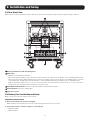
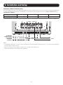
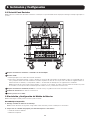
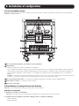
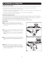
2.1 Rear Panel View
Note: Inspect the unit before performing installation. Make sure nothing inside the package is damaged. Keep the original packaging for future use.
A
Battery Terminal Blocks with Fast-Acting Fuses
B
DC Breaker:
• Battery over-current protection breaker.
• When servicing internal batteries, place the position of the breaker in the “O” position. This breaker does not interrupt DC power flow
between the UPS and any additional battery packs connected in parallel to the UPS. In the event a second battery pack is connected
to the battery bank, the DC voltage from the UPS Bat.+/- will flow through without any interruption to the second battery bank.
Note: The DC breaker is tripped (set to off, or the “O” position) at the factory. Do not flip the breaker’s actuator level to the on (“I”) position until the
battery pack has been successfully installed and properly connected to the UPS.
C
Input/Output Terminal Blocks: Connects to UPS and additional external battery cabinets.
D
Ground Terminal: Connects to earth ground.
E
Cable Access Ports
2.2 Battery Pack Installation and Setup
Note: To unload unit, removing the batteries may be required.
Unpacking and Inspection
1. Remove the battery pack from the packaging.
Note: The battery pack is extremely heavy. Be cautious when unpacking and lifting the unit to avoid injury.
2. Inspect the package contents for impact or other damage:
• Battery Pack Unit
• Owner’s Manual
B
CC
D
A
E

5
2. Installation and Setup
Selecting Installation Site
To minimize the possibility of damage to the battery bank and extend the life of the batteries, follow the instructions below:
1. Maintain at least 8 inches (20 cm) clearance between the unit’s rear panel and a wall (or other obstructions).
2. Do not block airflow to the unit’s ventilation openings.
3. Ensure the installation site environmental conditions are in accordance with the unit’s working specifications to avoid overheating and/or
excessive moisture.
4. Do not place the unit in a dusty or corrosive environment or near any flammable objects.
5. This unit is not designed for outdoor use.
Battery Pack Placement
Use the casters to move the battery pack for a short distance over a level, smooth, stable surface by pushing it from the front or rear (not
the side panels). Do not attempt to roll the unit over long distances. The battery pack should be moved close to its installation location
inside its shipping container before it is unpacked. (Use a forklift or pallet jack to move the shipping container.)
WARNING: Do not push or pull the battery cabinet by the side panels.
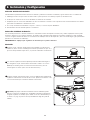
Leveling
1
After the battery pack has been moved to the installation location, use a
carpenter’s level to check the slope of the floor. If the floor slopes more than
1%, choose an alternate installation site.
2
Use an 18 mm open-end wrench to lower each leveler until it reaches the floor.
Make sure each leveler is in firm contact with the floor.
Note: Lower a leveler by turning it clockwise; raise a leveler by turning it counter-
clockwise
3
After lowering each leveler, use the carpenter’s level to confirm the enclosure
is level in all directions. Adjust the levelers as required until the battery pack is
level.
4
(Optional) To provide an additional measure of stability, you can use the
shipping brackets that secured the unit to the shipping pallet to secure
mounting points in the floor using user-supplied hardware or Tripp Lite’s
SmartRack Bolt-Down Kit (Part # SR331).
1
2
3
4

6
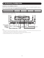
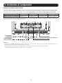
Connecting a UPS to the Battery Pack
The external battery pack will increase the battery runtime. As a result, recharge time will also increase. Follow the installation diagram below
to connect the battery pack to the UPS. For information on connecting to the UPS terminal block, refer to sections 3.6.2 and 3.7 of the
SUT UPS Owner’s Manual.
UPS System
SUT20K SUT30K SUT40K SUT60K
Battery Input Cable*
1 AWG (35 mm
2
) 1/0 AWG (50 mm
2
) 3/0 AWG (95 mm
2
) 250 kcmil (120 mm
2
)
* Use copper wire rated to 194°F (90°C) or higher. If using cable designed for a lower temperature capacity, please size wire according to local regulations.
2. Installation and Setup
+ + ––N N
TO ADDITIONAL
EXTERNAL BATTERY
PACK (NO WIRE
CONNECTION
OTHERWISE)
TO UPS
Notes:
• The DC breaker is tripped (set to off, or the “O” position) at the factory. Do not flip the breaker’s actuator lever to the on (“I”) position until the battery pack
has been properly connected to the UPS.
• Always use compression lugs with cabling to connect the UPS to the battery pack’s terminal block.
• Installer should determine correct wire type based on application.

7
2. Installation and Setup
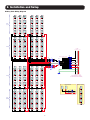
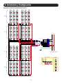
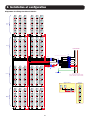
Battery Pack Wiring Diagram
Shelf 1
(Top)
Shelf 2
Shelf 3
Shelf 4
(Bottom)
-+
12V 9AH
-+
12V 9AH
-+
12V 9AH
-+
12V 9AH
-+
12V 9AH
-+
12V 9AH
-+
12V 9AH
-+
12V 9AH
-+
12V 9AH
-+
12V 9AH
-+
12V 9AH
-+
12V 9AH
-+
12V 9AH
-+
12V 9AH
-+
12V 9AH
-+
12V 9AH
-+
12V 9AH
-+
12V 9AH
-+
12V 9AH
-+
12V 9AH
-+
12V 9AH
-+
12V 9AH
-+
12V 9AH
-+
12V 9AH
-+
12V 9AH
-+
12V 9AH
-+
12V 9AH
-+
12V 9AH
-+
12V 9AH
-+
12V 9AH
-+
12V 9AH
-+
12V 9AH
-+
12V 9AH
-+
12V 9AH
-+
12V 9AH
-+
12V 9AH
-+
12V 9AH
-+
12V 9AH
-+
12V 9AH
-+
12V 9AH
-+
12V 9AH
-+
12V 9AH
-+
12V 9AH
-+
12V 9AH
-+
12V 9AH
-+
12V 9AH
-+
12V 9AH
-+
12V 9AH
-+
12V 9AH
-+
12V 9AH
-+
12V 9AH
-+
12V 9AH
-+
12V 9AH
-+
12V 9AH
-+
12V 9AH
-+
12V 9AH
-+
12V 9AH
-+
12V 9AH
-+
12V 9AH
-+
12V 9AH
-+
12V 9AH
-+
12V 9AH
-+
12V 9AH
-+
12V 9AH
-+
12V 9AH
-+
12V 9AH
-+
12V 9AH
-+
12V 9AH
-+
12V 9AH
-+
12V 9AH
-+
12V 9AH
-+
12V 9AH
-+
12V 9AH
-+
12V 9AH
-+
12V 9AH
-+
12V 9AH
-+
12V 9AH
-+
12V 9AH
-+
12V 9AH
-+
12V 9AH
-+
12V 9AH
-+
12V 9AH
-+
12V 9AH
-+
12V 9AH
-+
12V 9AH
-+
12V 9AH
-+
12V 9AH
-+
12V 9AH
-+
12V 9AH
-+
12V 9AH
-+
12V 9AH
-+
12V 9AH
-+
12V 9AH
-+
12V 9AH
-+
12V 9AH
-+
12V 9AH
F1
F2
F3
F4
F5
F6
F7
F8
CB1
TB2
TB3
TB1
GND STUD
TB4
Electrically Insulated Cu Busbars
TO UPS
TO EXTENSION BATT. CABINET
(NO WIRE CONNECTION OTHERWISE)
Neg PosNeu Ch Gnd
Neg PosNeu E Gnd
F1 - F8 63A 660V Fuse
1 BATTERY CARTRIDGE
+144V_L
-144V_L
+144V_R
-144V_R
-
+
144V
-
+
144V
CONNECTION SCHEME
-144V
+144V
4x 10 AWG
4x 10 AWG
4x 10 AWG
N
-+
12V 9AH
-+
12V 9AH
-+
12V 9AH
-+
12V 9AH
4x 10 AWG
1x 1/0 AWG
1x 1/0 AWG
1x 1/0 AWG
Left Half Right Half

8
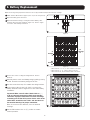
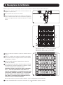
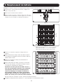
3. Battery Replacement
1
Make sure the DC breaker is tripped (set to off, or the “O” position).
2
Open the battery pack’s front door.
3
Open the terminal housings covering the internal battery cable
terminals. Disconnect the terminals (Figure 3-1). Refer to Figure
3-2 for the entire battery installation.
Figure 3-1
Figure 3-2
1. Disconnect the +1, +2, +3 and +4 cables on the right.
2. Disconnect the -1, -2, -3 and -4 cables on the left.
3. Disconnect the N1, N2, N3 and N4 cables in the center.
–1
through
–4
N1
through
N4
+1
through
+4
3
3
4
4
Remove the screws securing the wiring brackets. Remove
brackets.
5
Carefully remove each used battery string by pulling it out by
its tab. Insert the new battery string into the slot.
6
Use the screws from step 4 to reattach the wiring brackets.
7
In the reverse order of step 3 (4,3,2,1), reconnect the
battery terminals. Refer to Figure 3-2 for the entire battery
installation.
Important! Make sure all cables labeled with a +, -,
or N are correctly connected to their corresponding
connector. Improper connection can result in damage
to battery pack and/or UPS system. Please refer to the
white labels attached to the cables and the labels on
the terminal housings for proper connection.
Once all connectors are attached, close the terminal
housings.
8
Set the DC breaker to the on (“I”) position to resume
normal operation.
Note: The following battery replacement instructions are for Tripp Lite RBCSUT Replacement Batteries Cartridges.

9
5. UPS and Battery Recycling
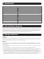
4. Specifications
Batteries can present a risk of electrical shock and burn from high short-circuit current. Observe proper precautions. Do not dispose of the
batteries in a fire. Do not open the batteries. Do not short or bridge the battery terminals with any object. Unplug and turn off the UPS before
performing battery replacement. Use tools with insulated handles. Battery replacement should be performed only by authorized service
personnel using the same number and type of batteries (Sealed Lead-Acid). The batteries are recyclable. Refer to your local codes for
disposal requirements or visit http://www.tripplite.com/support/recycling-program for recycling information.
6. Storage and Service
Storage
If the charging source remains off for an extended period of time, it should be turned on periodically to allow the batteries to recharge. The
charging source should be turned on and the batteries should be recharged for at least one uninterrupted 24-hour period every 3 months.
Failure to recharge the batteries periodically may cause permanent battery damage.
Service
Your Tripp Lite product is covered by the warranty described in this manual. A variety of Extended Warranty and On-Site Service Programs
are also available from Tripp Lite. For more information on service, visit www.tripplite.com/support. Before returning your product for service,
follow these steps:
1. Review the installation and operation procedures in this manual to insure that the service problem does not originate from a misreading
of the instructions.
2. If the problem continues, do not contact or return the product to the dealer. Instead, visit www.tripplite.com/support.
3.
If the problem requires service, visit www.tripplite.com/support and click the Product Returns link. From here you can request a Returned
Material Authorization (RMA) number, which is required for service. This simple on-line form will ask for your unit’s model and serial
numbers, along with other general purchaser information. The RMA number, along with shipping instructions will be emailed to you. Any
damages (direct, indirect, special or consequential) to the product incurred during shipment to Tripp Lite or an authorized Tripp Lite service
center are not covered under warranty. Products shipped to Tripp Lite or an authorized Tripp Lite service center must have transportation
charges prepaid. Mark the RMA number on the outside of the package. If the product is within its warranty period, enclose a copy of your
sales receipt. Return the product for service using an insured carrier to the address given to you when you request the RMA.
Battery
DC System Voltage +/- 144V DC
Battery Type 12V 9Ah
Battery Quantity 96
Battery Pack Ah 36
UPS Connection Hardwire (3-Pole Terminal Block)
Physical
Unit Dimensions (H x W x D) 23.5 x 30.08 x 33.58 in. / 1999 x 1016 x 749 mm
Unit Weight 771.62 lb. / 350 kg
Material of Construction Steel
External Battery Pack Form Factor Tower
Environment
Storage Temperature -4°F to 104°F / -20°C to 40°C
Operating Temperature 32°F to 104°F / 0°C to 40°C
Operating Elevation 0 to 10,000 ft. / 0 to 3,000 m
Humidity 5% to 95% RH (Non-Condensing)

10
1111 W. 35th Street, Chicago, IL 60609 USA • www.tripplite.com/support
7. Warranty
1-YEAR LIMITED WARRANTY
Seller warrants this product, if used in accordance with all applicable instructions, to be free
from original defects in material and workmanship for a period of one (1) year from the date
of initial purchase. If the product should prove defective in material or workmanship within
that period, Seller will repair or replace the product, in its sole discretion. Service under this
Warranty can only be obtained by your delivering or shipping the product (with all shipping or
delivery charges prepaid) to: Tripp Lite, 1111 W. 35th Street, Chicago, IL 60609 USA. Seller
will pay return shipping charges. Visit www.tripplite.com/support before sending any equipment
back for repair.
THIS WARRANTY DOES NOT APPLY TO NORMAL WEAR OR TO DAMAGE RESULTING FROM
ACCIDENT, MISUSE, ABUSE OR NEGLECT. SELLER MAKES NO EXPRESS WARRANTIES
OTHER THAN THE WARRANTY EXPRESSLY SET FORTH HEREIN. EXCEPT TO THE EXTENT
PROHIBITED BY APPLICABLE LAW, ALL IMPLIED WARRANTIES, INCLUDING ALL WARRANTIES
OF MERCHANTABILITY OR FITNESS, ARE LIMITED IN DURATION TO THE WARRANTY PERIOD
SET FORTH ABOVE; AND THIS WARRANTY EXPRESSLY EXCLUDES ALL INCIDENTAL AND
CONSEQUENTIAL DAMAGES. (Some states do not allow limitations on how long an implied
warranty lasts, and some states do not allow the exclusion or limitation of incidental or
consequential damages, so the above limitations or exclusions may not apply to you. This
Warranty gives you specific legal rights, and you may have other rights which vary from
jurisdiction to jurisdiction).
WARNING: The individual user should take care to determine prior to use whether this device
is suitable, adequate or safe for the use intended. Since individual applications are subject to
great variation, the manufacturer makes no representation or warranty as to the suitability or
fitness of these devices for any specific application.
Regulatory Compliance Identification Numbers
For the purpose of regulatory compliance certifications and identification, your Tripp Lite product
has been assigned a unique series number. The series number can be found on the product
nameplate label, along with all required approval markings and information. When requesting
compliance information for this product, always refer to the series number. The series number
should not be confused with the marketing name or model number of the product.
WEEE Compliance Information for Tripp Lite Customers and Recyclers
(European Union)
Under the Waste Electrical and Electronic Equipment (WEEE) Directive and
implementing regulations, when customers buy new electrical and electronic equipment
from Tripp Lite they are entitled to:
• Send old equipment for recycling on a one-for-one, like-for-like basis (this varies
depending on the country)
• Send the new equipment back for recycling when this ultimately becomes waste
Tripp Lite has a policy of continuous improvement. Specifications are subject to change without
notice.

11
Manual del Propietario
1111 W. 35th Street, Chicago, IL 60609 USA • www.tripplite.com/support
Copyright © 2018 Tripp Lite. Todos los derechos reservados.
Módelo de Baterías Externo
para Uso con Sistemas UPS SUT Trifásicos de 208V
Modelo: BP288VEBP
(Número de Serie: AG-01A2)
English 1 • Français 21

12
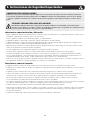
1. Instrucciones de Seguridad Importantes
CONSERVE ESTAS INSTRUCCIONES
Todas las secciones de este manual contienen instrucciones y advertencias que deben observarse durante la instalación
y la operación del gabinete de batería aquí descrito. Lea TODAS las instrucciones detenidamente antes de mover, instalar
o conectar el gabinete de batería. Caso contrario, puede afectar la garantía y causar daños materiales o lesiones físicas
graves.
¡PELIGRO! ¡RIESGO LETAL POR ALTO VOLTAJE!
El tendido del cableado debe estar a cargo de un electricista calificado, en conformidad con las advertencias
descritas en este manual y en todos los códigos de seguridad y eléctricos que correspondan. Si el cableado no fuese
correcto, puede causar lesiones físicas graves y daños materiales.
Advertencias sobre Instalación y Ubicación
• Instale el gabinete de batería en un ambiente interior controlado, alejado de humedad excesiva, temperaturas extremas, líquidos y gases
inflamables, contaminantes conductores, polvo o luz solar directa.
• Instale el gabinete de batería en una ubicación nivelada y con estructura firme.
• El gabinete de batería es muy pesado. Tenga sumo cuidado cuando mueva o levante la unidad.
• El gabinete de batería solo debe funcionar a una temperatura entre 0° C y 40° C y entre 30 - 90% de humedad sin condensación en
interiores. Para mejores resultados, mantenga la temperatura ambiente a 25° C.
• Mantenga espacio suficiente en la parte delantera y posterior del gabinete para una correcta ventilación. No bloquee, cubra ni coloque
objetos en las aberturas de ventilación externas del gabinete.
• No apoye ningún objeto sobre el gabinete de batería, especialmente recipientes con líquido.
• No intente apilar el gabinete de batería. Si lo hiciera, puede dañarlo de forma definitiva y causar lesiones físicas graves.
• No intente desembalar ni mover el gabinete sin asistencia. Use un equipo de manipulación con capacidad apropiada para soportar el
peso y la carga del gabinete, como montacargas y gatos mecánicos para tarimas. (Extienda las horquillas por completo debajo de la
carga. Ábralas al máximo ancho posible. Levante el gabinete por la base solamente. Use calzado protector.)
• Para uso en caso de emergencia, instale un extinguidor cerificado para incendios de equipos eléctricos conectados (clasificación clase C o
uno exactamente equivalente, con agente extinguidor no conductor) cerca del gabinete.
Advertencias sobre la Conexión
• El gabinete de batería contiene alto voltaje peligroso que puede causar lesiones físicas o la muerte por descarga eléctrica.
• El gabinete tiene su propia fuente de energía. Las terminales de salida pueden estar energizadas cuando el gabinete no está conectado a
un sistema UPS.
• El gabinete se debe conectar a tierra como corresponda según todas las regulaciones de cableado eléctrico previstas.
• El uso de este equipo en aplicaciones de soporte de vida en donde la falla de este equipo pueda razonablemente hacer suponer que
causará fallas en el equipo de soporte de vida o afecte significativamente su seguridad o efectividad, no está recomendado.
• Desconecte todas las fuentes de alimentación de entrada y salida antes de instalar los cables o realizar conexiones eléctricas.
• Use un cable flexible de longitud suficiente para permitir las tareas de servicio del gabinete.
• Use casquillos para tapar los cables de terminación y evitar que los extremos deshilachados entren en corto en los bloques de terminales.
Use cable con clasificación VW-1, FT-1 o superior. Use manguitos para los cables y abrazaderas para los conectores.
• Confirme que todos los cables estén marcados correctamente según su finalidad, polaridad y diámetro.
• Para respetar la polaridad correcta, conecte el negativo con el negativo y el positivo con el positivo (y el filamento central con el filamento
central, según corresponda). El hecho de no respetar la polaridad correcta puede dañar las baterías y causar riesgo grave de lesiones
físicas y daños materiales.
• El tendido del cableado debe estar a cargo solamente de electricistas calificados y capacitados.

13
1. Instrucciones de Seguridad Importantes
Advertencias sobre Batería
• El gabinete de batería no requiere mantenimiento regular por parte del usuario. No incluye partes que requieran tareas de servicio a cargo
del usuario. Solo personal técnico calificado y familiarizado con todas las precauciones requeridas puede abrir los paneles de acceso por
algún motivo. Mantenga al personal no autorizado alejado de las baterías.
• El gabinete de batería contiene baterías de plomo ácido recombinantes reguladas con válvula (VRLA). No intente agregar agua a las
baterías ni tomar una muestra del peso específico del electrolito.
• Las baterías de plomo ácido recombinantes reguladas con válvula (VRLA) pueden contener una mezcla explosiva de gas hidrógeno. NO
FUME cerca de las baterías. NO encienda llamas ni chispas cerca de las baterías. Descargue la electricidad estática del cuerpo antes de
tocar las baterías. NO abra ni altere las baterías, la emisión de electrolito es dañina para la piel y los ojos, y puede ser tóxica. NO deseche
las baterías mediante incineración; pueden explotar.
• Debido a que las baterías presentan un peligro de choque eléctrico y quemaduras por las altas corrientes de cortocircuito, tome las
precauciones adecuadas. No deseche las baterías en un incinerador. No abra las baterías. No ponga los terminales de la batería en corto
o en puente con ningún objeto. Apague y desconecte el UPS antes de reemplazar la batería. Sólo debe cambiar las baterías personal
técnico debidamente capacitado. Use herramientas con mangos aislados y reemplace las baterías existentes con el mismo número y tipo
de baterías nuevas (plomo-ácido selladas). No hay partes dentro del gabinete de baterías a las que el usuario pueda dar servicio. Las
baterías del UPS son reciclables. Consulte la reglamentación local para los requisitos de disposición de desechos o visita
http://www.tripplite.com/support/recycling-program para reciclar información. Tripp Lite ofrece una línea completa de Cartuchos de
reemplazo de batería para UPS (R.B.C.). Visite Tripp Lite en la web en http://www.tripplite.com/products/battery-finder/ para localizar la
batería de reemplazo específica para su UPS.
• Reemplace las baterías por otras equivalentes (mismo número y tipo) que puede comprar en Tripp Lite.
• El reemplazo del fusible debe estar a cargo solo de personal de servicio calificado. Solo reemplace por el mismo tipo y clasificación: 63A
660V.
• Las baterías son reciclables. Para los requisitos de desecho, consulte los códigos locales. Solo deseche las baterías mediante los canales
autorizados en conformidad con todas las regulaciones locales, estatales y nacionales que correspondan.
• No conecte ni desconecte las baterías cuando el sistema UPS esté funcionando con suministro de la batería o cuando la unidad no se
encuentre en modo de derivación. Desconecte la fuente de carga antes de conectar o desconectar las terminales de la batería.
• Si la fuente de carga permanece apagada por un período prolongado, debe encenderse periódicamente para permitir la recarga de las
baterías. Debe encenderse la unidad de carga y recargarse las baterías durante 24 horas ininterrumpidas como mínimo cada 3 meses. Si
no se recargaran las baterías periódicamente puede causar un daño definitivo a la batería.
• Deje que las baterías se carguen durante 24 horas ininterrumpidas después de la instalación.

14
2. Instalación y Configuración
2.1 Vista del Panel Posterior
Nota: Inspeccione la unidad antes de realizar la instalación. Confirme que no haya nada dañado dentro del paquete. Mantenga el embalaje original para uso
posterior.
A
Bloques de Terminales de Baterías con Fusibles de Acción Rápida
B
Breaker de CD:
• Breaker para protección contra sobrecorriente de batería.
• Al dar servicio las baterías internas, coloque el breaker en la posición “O”. Este breaker no interrumpe el flujo de corriente CD entre el
UPS y cualquier módulo adicional de baterías conectado en paralelo al UPS. En caso de que esté conectado un segundo módulo de
baterías al banco de baterías, el voltaje CD de la Bat.+/- del UPS fluirá sin interrupciones al segundo banco de baterías.
Nota: El breaker de CD es desconectado (sistema apagado, o la posición “O”) en la fábrica. No cambie el nivel del actuador del breaker a la posición
de encendido (“I”) hasta que el módulo de baterías haya sido instalado con éxito y correctamente conectado al UPS.
C
Bloques de Terminales de Entrada / Salida: Se conectan al UPS y los gabinetes adicionales de baterías externas.
D
Terminal de Tierra Física: Se Conecta a Tierra Física.
E
Puertos para Acceso al Cable
2.2 Instalación y Configuración del Módulo de Baterías
Nota: Para descargar la unidad, puede ser necesario quitar las baterías.
Desembalaje e Inspección
1. Extraiga el módulo de baterías del embalaje.
Nota: El módulo de baterías es muy pesado. Tenga cuidado cuando desembale y levante la unidad para no causar daños.
2. Inspeccione el contenido del paquete para detectar impactos u otros daños:
• Unidad de módulo de baterías
• Manual del Propietario
B
CC
D
A
E

15
2. Instalación y Configuración
Selección del Sitio de Instalación
Para minimizar la posibilidad de daños al banco de baterías y extender la vida útil de las baterías, siga las instrucciones a continuación:
1. Mantenga al menos un espacio libre de 20 cm entre el panel posterior de la unidad y la pared (u otra obstrucción).
2. No bloquee la circulación de aire en las aberturas de ventilación de la unidad.
3. Compruebe que las condiciones ambientales del sitio de instalación coincidan con las especificaciones de funcionamiento de la unidad
para evitar recalentamiento o humedad excesiva.
4. No coloque la unidad en un ambiente con polvo o corrosivo, ni cerca de objetos inflamables.
5. Esta unidad no ha sido diseñada para uso en exteriores.
Colocación del Módulo de Baterías
Use las ruedas para mover el módulo de baterías a corta distancia sobre una superficie nivelada, lisa y estable empujando desde la parte
delantera o trasera (no de los paneles laterales). No intente rodar la unidad a largas distancias. El módulo de baterías se debe desplazar
cerca de su lugar de instalación dentro de su contenedor de embarque antes de desempacarlo. (Utilice un montacargas o gato para tarimas
para mover el contenedor de embarque).
ADVERTENCIA: No empuje ni jale el gabinete de la batería por los paneles laterales.
1
2
3
4
Nivelación
1
Después de que el módulo de baterías ha sido trasladado a la ubicación de
instalación, utilice un nivel de burbuja para verificar la pendiente del piso. Si el
piso tiene una pendiente mayor del 1%, elija un sitio alternativo de instalación.
2
Use una llave española de 18 mm para bajar cada nivelador hasta llegar al
piso. Asegúrese de que cada nivelador está en firme contacto con el suelo.
Nota: Baje un nivelador girando en sentido de las manecillas del reloj; eleve un
nivelador girando en sentido opuesto al de las manecillas del reloj
3
Después de bajar cada nivelador, utilice el nivel de burbuja para confirmar que
el gabinete está nivelado en todas las direcciones. Ajuste los niveladores como
sea necesario hasta que el módulo de baterías esté nivelado.
4
(Opcional) Para proporcionar una medida adicional de estabilidad, puede
utilizar los soportes de embargue que aseguraban la unidad a la tarima para
asegurar los puntos de montaje al piso usando accesorios suministrados por
el usuario o el juego de perno de anclaje SmartRack de Tripp Lite (parte #
SR331).

16
2. Instalación y Configuración
Conexión de un UPS al Módulo de Baterías
El módulo externo de baterías aumentará el tiempo de autonomía. Como resultado, el tiempo de recarga también aumentará. Siga el dia-
grama de instalación para conectar el módulo de baterías al UPS. Para obtener información sobre la conexión a al bloque de conexiones del
UPS, consulte las secciones 3.6.2 y 3.7 del Manual del Propietario del UPS SUT.
Sistema UPS
SUT20K SUT30K SUT40K SUT60K
Cable de Entrada de Batería*
1 AWG (35 mm
2
) 1/0 AWG (50 mm
2
) 3/0 AWG (95 mm
2
) 250 kcmil (120 mm
2
)
* Use cable de cobre especificado para 90 °C (194 °F) o mayor. Si usa un cable diseñado para una capacidad de temperatura más baja, por favor ajuste el
tamaño del cable conforme a las regulaciones locales.
+ + ––N N
A MÓDULO EXTERNO
ADICIONAL DE
BATERÍAS (SIN
CONEXIÓN DE
CABLE)
AL UPS
Notas:
• El breaker de CD es desconectado (establecido en apagado, o la posición “O”) en la fábrica. No cambie la palanca del actuador del breaker a la posición
de encendido (“I”) hasta que el módulo de baterías haya sido correctamente conectado al UPS.
• Siempre use zapatas de compresión con el cableado para conectar el UPS al bloque de terminales de la batería.
• El instalador debe determinar el tipo correcto de cable basado en la aplicación.

17
2. Instalación y Configuración
Diagrama de Cableado del Módulo de Baterías
Repisa 1
(Superior)
Repisa 2
Repisa 3
Repisa 4
(Inferior)
-+
12V 9AH
-+
12V 9AH
-+
12V 9AH
-+
12V 9AH
-+
12V 9AH
-+
12V 9AH
-+
12V 9AH
-+
12V 9AH
-+
12V 9AH
-+
12V 9AH
-+
12V 9AH
-+
12V 9AH
-+
12V 9AH
-+
12V 9AH
-+
12V 9AH
-+
12V 9AH
-+
12V 9AH
-+
12V 9AH
-+
12V 9AH
-+
12V 9AH
-+
12V 9AH
-+
12V 9AH
-+
12V 9AH
-+
12V 9AH
-+
12V 9AH
-+
12V 9AH
-+
12V 9AH
-+
12V 9AH
-+
12V 9AH
-+
12V 9AH
-+
12V 9AH
-+
12V 9AH
-+
12V 9AH
-+
12V 9AH
-+
12V 9AH
-+
12V 9AH
-+
12V 9AH
-+
12V 9AH
-+
12V 9AH
-+
12V 9AH
-+
12V 9AH
-+
12V 9AH
-+
12V 9AH
-+
12V 9AH
-+
12V 9AH
-+
12V 9AH
-+
12V 9AH
-+
12V 9AH
-+
12V 9AH
-+
12V 9AH
-+
12V 9AH
-+
12V 9AH
-+
12V 9AH
-+
12V 9AH
-+
12V 9AH
-+
12V 9AH
-+
12V 9AH
-+
12V 9AH
-+
12V 9AH
-+
12V 9AH
-+
12V 9AH
-+
12V 9AH
-+
12V 9AH
-+
12V 9AH
-+
12V 9AH
-+
12V 9AH
-+
12V 9AH
-+
12V 9AH
-+
12V 9AH
-+
12V 9AH
-+
12V 9AH
-+
12V 9AH
-+
12V 9AH
-+
12V 9AH
-+
12V 9AH
-+
12V 9AH
-+
12V 9AH
-+
12V 9AH
-+
12V 9AH
-+
12V 9AH
-+
12V 9AH
-+
12V 9AH
-+
12V 9AH
-+
12V 9AH
-+
12V 9AH
-+
12V 9AH
-+
12V 9AH
-+
12V 9AH
-+
12V 9AH
-+
12V 9AH
-+
12V 9AH
-+
12V 9AH
-+
12V 9AH
-+
12V 9AH
-+
12V 9AH
-+
12V 9AH
F1
F2
F3
F4
F5
F6
F7
F8
CB1
TB2
TB3
TB1
PERNO DE TIERRA
TB4
Barras de Bus de Cobre Aisladas Eléctricamente
AL UPS
AL GABINETE DE BATERÍA DE EXTENSIÓN
(SIN CONEXIÓN DE CABLES)
Neg Pos Neu Ch Tierra
Neg Pos Neu E Tierra
F1 - F8 Fusible de 63A 660V
1 CARTUCHO
DE BATERÍA
+144V_L
-144V_L
+144V_R
-144V_R
-
+
144V
-
+
144V
ESQUEMA DE CONEXIONES
-144V
+144V
4x 10 AWG
4x 10 AWG
4x 10 AWG
N
-+
12V 9AH
-+
12V 9AH
-+
12V 9AH
-+
12V 9AH
4x 10 AWG
1x 1/0 AWG
1x 1/0 AWG
1x 1/0 AWG
Mitad Izquierda Mitad Derecha

18
3. Reemplazo de la Batería
1
Asegure que el breaker de CD esté desconectado (establecido en
apagado o la posición “O”).
2
Abre la puerta frontal del módulo de baterías.
3
Abra los alojamiento de terminales que cubren los terminales del
cable de la batería interna. Desconecte las terminales (Figura 3-1).
Refiérase a la Figura 3-2 para consultar la instalación de la batería
entera.
Figura 3-1
Figura 3-2
1. Desconecte los cables +1, +2, +3 y +4 a la derecha.
2. Desconecte los cables -1, -2, -3 y -4 a la izquierda.
3. Desconecte los cables N1, N2, N3 y N4 al centro.
–1
a
–4
N1
a
N4
+1
a
+4
3
3
4
4
Retire los tornillos que sujetan los soportes de cableado. Retire los
soportes.
5
Retire con cuidado cada cadena de baterías usado tirando
de él hacia fuera por su lengüeta. Inserte la nueva cadena
de baterías en la ranura.
6
Utilice los tornillos del paso 4 para volver a colocar los
soportes de cableado.
7
En el orden inverso del paso 3 (4,3,2,1), vuelva a conectar
las terminales de la batería. Refiérase a la Figura 3-2 para
consultar la instalación de la batería entera.
¡Importante! Asegure que todos los cables etiquetados
con +, - o N estén correctamente conectados a su
conector correspondiente. La conexión incorrecta puede
causar daños al módulo de baterías y/o al sistema UPS.
Por favor refiérase a las etiquetas blancas adheridas
a los cables y las etiquetas en los alojamientos de las
terminales para una conexión apropiada.
Nota: Las siguientes instrucciones de reemplazo de batería son para cartuchos de baterías de reemplazo RBCSUT de Tripp Lite.
Una vez que todos los conectores estén instalados, cierre los alojamientos de las terminales.
8
Coloque el breaker de CD en la posición encendido (“I”) para reanudar la operación normal.

19
6. Almacenamiento y Servicio
5. Reciclado de la Batería y el UPS
Almacenamiento
Si la fuente de carga permanece apagada por un período prolongado, debe encenderse periódicamente para permitir la recarga de las
baterías. Debe encenderse la unidad de carga y recargarse las baterías durante 24 horas ininterrumpidas como mínimo cada 3 meses. Si
no se recargan las baterías periódicamente, puede causar un daño definitivo a la batería.
Servicio técnico
Su producto Tripp Lite está cubierto por la garantía descrita en este manual. Tripp Lite también pone a su disposición una variedad de
Garantías extendidas y Programas de servicio técnico en el sitio. Si desea más información sobre el servicio técnico, visite www.tripplite.com/
support. Antes de devolver su producto para servicio técnico, siga estos pasos:
1. Revise la instalación y los procedimientos de operación que se encuentran en este manual para asegurarse de que el problema de
servicio no se debe a una mala lectura de las instrucciones.
2. Si el problema persiste, no se comunique ni devuelva el producto al mayorista. En cambio, visite www.tripplite.com/support.
3. Si el problema exige servicio técnico, visite www.tripplite.com/support y haga clic en el enlace Devoluciones de productos. Desde
aquí puede solicitar un número de Autorización de Material Devuelto (RMA), que se necesita para el servicio técnico. En este sencillo
formulario en línea se le solicitarán los números de serie y modelo de la unidad, junto con otra información general del comprador. El
número RMA y las instrucciones para el envío se le enviarán por correo electrónico. La presente garantía no cubre ningún daño (directo,
indirecto, especial o consecuencial) del producto que ocurra durante el envío a Tripp Lite o a un centro de servicio técnico de Tripp Lite
autorizado. Los productos enviados a Tripp Lite o a un centro de servicio técnico de Tripp Lite autorizado deben tener prepagos los cargos
de transporte. Escriba el número RMA en el exterior del embalaje. Si el producto se encuentra dentro del período de garantía, adjunte
una copia de su recibo de venta. Envíe el producto para servicio técnico mediante un transportador asegurado a la dirección que se le
proporcionó cuando solicitó el número RMA.
Las baterías pueden presentar un riesgo de descarga eléctrica y quemaduras por la alta corriente de cortocircuito. Observe las precauciones
apropiadas. No deseche las baterías en el fuego. No abra las baterías. No ponga en corto o puentee las terminales de la batería con ningún
objeto. Desenchufe y apague el UPS antes de ejecutar el reemplazo de la batería. Use herramientas con mangos aislados. El reemplazo
de la batería debe realizarlo solo el personal de servicio autorizado usando el mismo número y tipo de baterías (Plomo-Ácido Selladas). Las
baterías son reciclables. Para información sobre el reciclado, consulte sus códigos locales para los requisitos de desecho o visite
http://www.tripplite.com/support/recycling-program.
4. Especificaciones
Batería
Voltaje CD del Sistema +/- 144V CD
Tipo de Batería 12V 9Ah
Cantidad de Baterías 96
Módulo de Baterías Ah 36
Conexión del UPS Instalación Eléctrica Permanente (Bloque de Terminales de 3 Polos)
Físicas
Dimensiones de la Unidad (Al x An x Pr) 1999 x 1016 x 749 mm [3.5" x 30.08" x 33.58"]
Peso de la Unidad 350 kg [771.62 lb]
Material de Construcción Acero
Factor de Forma del Módulo de Batería Externa Torre
Entorno
Temperatura de Almacenamiento -20 °C a 40 °C [-4 °F a 104 °F]
Temperatura de Operación 0 °C a 40 °C [32 °F a 104 °F]
Elevación de Operación 0 ~ 3000 m [0 ~ 10,000 pies]
Humedad De 5% a 95% de HR (Sin Condensación)

20
7. Garantía
GARANTÍA LIMITADA DE 1 AÑO
El vendedor garantiza que este producto no tiene defectos originales de materiales ni de mano
de obra por un período de un (1) año a partir de la fecha original de compra, si se utiliza de
acuerdo con todas las instrucciones correspondientes. En caso de demostrarse dentro de
ese período que el producto tiene defectos de materiales o de mano de obra, el vendedor lo
reparará o reemplazará a su exclusiva discreción. El servicio técnico bajo esta garantía solo
puede ser obtenido si usted entrega o envía el producto (con todos los cargos de envío o
entrega prepagos) a: Tripp Lite; 1111 W. 35th Street; Chicago IL 60609; EE. UU. El vendedor
abonará los cargos de envío de devolución. Visite www.tripplite.com/support antes de enviar
cualquier equipo para reparación.
ESTA GARANTÍA NO CUBRE EL DESGASTE NORMAL NI LOS DAÑOS CAUSADOS POR
ACCIDENTES, MAL USO, ABUSO O NEGLIGENCIA. EL VENDEDOR NO OFRECE NINGUNA
GARANTÍA EXPRESA QUE NO SEA LA ESTABLECIDA EXPRESAMENTE EN EL PRESENTE
DOCUMENTO. EXCEPTO EN LA MEDIDA EN QUE LO PROHIBAN LAS LEYES APLICABLES, LA
DURACIÓN DE TODAS LAS GARANTÍAS IMPLÍCITAS, INCLUIDAS LAS DE COMERCIABILIDAD
O APTITUD, SE LIMITA AL PERÍODO DE GARANTÍA ANTES MENCIONADO Y ESTA GARANTÍA
EXCLUYE EXPRESAMENTE TODOS LOS DAÑOS INCIDENTALES E INDIRECTOS. (Algunos Estados
no permiten las limitaciones a la duración de una garantía implícita y algunos Estados no
permiten la exclusión o limitación de los daños incidentales o indirectos, de modo que las
limitaciones o exclusiones antes mencionadas pueden no corresponder en su caso. Esta
garantía le otorga derechos legales específicos y usted puede tener otros derechos que varían
de una jurisdicción a otra).
ADVERTENCIA: Antes de usar este dispositivo, cada usuario debe ocuparse de determinar
si es apto, adecuado o seguro para el uso que pretende darle. Dado que las aplicaciones
individuales están sujetas a diversas variaciones, el fabricante no representa ni garantiza la
idoneidad o condición de estos dispositivos para cualquier aplicación específica.
Cumplimiento de las normas de los números de identificación
Para fines de identificación y certificación del cumplimiento de las normas, su producto Tripp
Lite tiene asignado un número de serie único. Puede encontrar el número de serie en la
etiqueta de la placa de identificación del producto, junto con los símbolos de aprobación e
información requeridos. Al solicitar información sobre el cumplimiento de las normas para este
producto, siempre mencione el número de serie. El número de serie no debe ser confundido
con el nombre de identificación ni con el número de modelo del producto.
Información de sobre Cumplimiento de la WEEE para Clientes de Tripp Lite y
Recicladores (Unión Europea)
Según la Directiva de Residuos de Aparatos Eléctricos y Electrónicos (Waste Electrical
and Electronic Equipment, WEEE, ) y sus reglamentos, cuando los clientes compran
nuevos equipos eléctricos y electrónicos a Tripp Lite, tienen derecho a:
• Enviar equipos antiguos para reciclaje según una base de uno por uno, entre
productos similares (esto varía dependiendo del país)
• Enviar el equipo nuevo de vuelta para reciclaje cuando este se convierta finalmente
en desecho
Tripp Lite tiene una política de mejora continua. Las especificaciones están sujetas a cambio
sin previo aviso.
1111 W. 35th Street, Chicago, IL 60609 USA • www.tripplite.com/support
Page is loading ...
Page is loading ...
Page is loading ...
Page is loading ...
Page is loading ...
Page is loading ...
Page is loading ...
Page is loading ...
Page is loading ...
Page is loading ...
Page is loading ...
Page is loading ...
-
 1
1
-
 2
2
-
 3
3
-
 4
4
-
 5
5
-
 6
6
-
 7
7
-
 8
8
-
 9
9
-
 10
10
-
 11
11
-
 12
12
-
 13
13
-
 14
14
-
 15
15
-
 16
16
-
 17
17
-
 18
18
-
 19
19
-
 20
20
-
 21
21
-
 22
22
-
 23
23
-
 24
24
-
 25
25
-
 26
26
-
 27
27
-
 28
28
-
 29
29
-
 30
30
-
 31
31
-
 32
32


Tripp Lite BP288VEBP Owner's manual
- Type
- Owner's manual
Ask a question and I''ll find the answer in the document
Finding information in a document is now easier with AI
in other languages
Related papers
-
Tripp Lite BP288VEBPNB Owner's manual
-
-
-
-
-
-
-
-
-
Tripp Lite 3-Phase User manual
Other documents
-
ATEN BP24V18AH User manual
-
Legrand Keor SPX 1000 ВА (310302) User manual
-
SECOMP ProSecure II 1500 RM2U User manual
-
 BlueWalker PowerWalker VI 1200 LCD/FR User manual
-
Approx APPUPS7 Specification
-
 BlueWalker VI 1200 IEC Specification
-
OPTI-UPS DS3000B-RM User manual
-
Eaton 9SXEBM36R Installation and User Manual
-
 Lapara LA-ON-2K-RACK Datasheet
-
Eaton 5E2000IUSB Specification


