
© C. & E. FEIN GmbH. Printed in Germany. Abbildungen unverbindlich. Technische Änderungen vorbehalten. 3 41 01 179 21 0 BY 2013.06 DE.
FEIN Service
USA
FEIN Power Tools Inc.
1030 Alcon Street
Pittsburgh, PA 15220
Telephone: (412) 922-8886
Toll Free: 1-800-441-9878
www.feinus.com
Canada
FEIN Canadian Power Tool
Company
323 Traders Boulevard East
Mississauga, Ontario L4Z 2E5
Telephone.: (905) 8901390
Toll Free: 1-800-265-2581
FEIN Canadian Power Tool
Company
2810 De Miniac
St. Laurent, Quebec H4S 1K9
Telephone: (514) 331-7390
Toll Free: 1-800-789-8181
www.fein.com
Headquarter
C. & E. FEIN GmbH
Hans-Fein-Straße 81
D-73529 Schwäbisch Gmünd-Bargau
www.fein.com
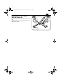
BLS1.6E 7 230 34
BLS2.5E 7 230 35
BLS3.5 7 230 23
BLS4.2 7 230 24
BSS1.6 E 7 230 31
BSS1.6CE 7 230 32
BSS2.0E 7 230 33
OBJ_DOKU-0000002881-001.fm Page 1 Friday, June 7, 2013 10:37 AM

2
Instruction Manual
Mode d'emploi
Instrucciones de uso
en
3
fr
26
es
50
OBJ_BUCH-0000000109-001.book Page 2 Friday, June 7, 2013 10:26 AM

3
en
en
For your safety.
Read all safety warnings and
all instructions. Failure to fol-
low the warnings and instructions may result
in electric shock, fire and/or serious injury.
Save all warnings and instructions for future-
reference.
Do not use this power tool before you
have thoroughly read and completely
understood this Instruction Manual, including
the figures, specifications, safety regulations
and the signs indicating DANGER, WARN-
ING and CAUTION.
Only carry out such operations with this
power tool as intended for by FEIN. Only use
application tools and accessories that have
been released by FEIN.
Please also observe the relevant national
industrial safety regulations.
Non-observance of the safety instructions in
the said documentation can lead to an electric
shock, burns and/or severe injuries.
This Instruction Manual should be kept for
later use and enclosed with the power tool,
should it be passed on or sold.
SAVE THESE INSTRUCTIONS.
The term “power tool” in the warnings refers
to your mains-operated (corded) power tool
or battery operated (cordless) power tool.
General safety rules.
1) Work area safety
a)Keep work area clean and well lit. Clut-
tered or dark areas invite accidents.
b)Do not operate power tools in explosive
atmospheres, such as in the presence of
flammable liquids, gases or dust. Power
tools create sparks which may ignite the
dust or fumes.
c) Keep children and bystanders away
while operating a power tool. Distrac-
tion can cause you to lose control.
2) Electrical safety
a)Power tool plugs must match the outlet.
Never modify the plug in any way. Do not
use any adapter plugs with earthed
(grounded) power tools. Unmodified
plugs and matching outlets will reduce
risk of electric shock.
b)Avoid body contact with earthed or
grounded surfaces such as pipes, radia-
tors, ranges and refrigerators. There is
an increased risk of electric shock if
your body is earthed or grounded.
c) Do not expose power tools to rain or wet
conditions. Water entering a power
tool will increase the risk of electric
shock.
d)Do not abuse the cord. Never use the
cord for carrying, pulling or unplugging
the power tool. Keep cord away from
heat, oil, sharp edges or moving parts.
Damaged or entangled cords increase
the risk of electric shock.
e) When operating a power tool outdoors,
use an extension cord suitable for out-
door use. Use of a cord suitable for out-
door use reduces the risk of electric
shock.
f) If operating a power tool in a damp loca-
tion is unavoidable, use a residual cur-
rent device (RCD) protected supply. Use
of an RCD reduces the risk of electric
shock.
3) Personal safety
a)Stay alert, watch what you are doing
and use common sense when operating
a power tool. Do not use a power tool
while you are tired or under the influ-
ence of drugs, alcohol or medication. A
moment of inattention while operating
power tools may result in serious per-
sonal injury.
b)Use personal protective equipment.
Always wear eye protection. Protective
equipment such as dust mask, non-skid
safety shoes, hard hat, or hearing pro-
tection used for appropriate conditions
will reduce personal injuries.
c) Prevent unintentional starting. Ensure
the switch is in the off-position before
connecting to power source and/or bat-
tery pack, picking up or carrying the
tool. Carrying power tools with your
finger on the switch or energising
power tools that have the switch on
invites accidents.
d)Remove any adjusting key or wrench
before turning the power tool on. A
wrench or a key left attached to a rotat-
ing part of the power tool may result in
personal injury.
WARNING
OBJ_BUCH-0000000109-001.book Page 3 Friday, June 7, 2013 10:26 AM

4
en
e) Do not overreach. Keep proper footing
and balance at all times. This enables
better control of the power tool in
unexpected situations.
f) Dress properly. Do not wear loose cloth-
ing or jewelery. Keep your hair, clothing
and gloves away from moving parts.
Loose clothes, jewelry or long hair can
be caught in moving parts.
g)If devices are provided for the connec-
tion of dust extraction and collection
facilities, ensure these are connected
and properly used. Use of dust collec-
tion can reduce dust-related hazards.
4) Power tool use and care
a)Do not force the power tool. Use the cor-
rect power tool for your application. The
correct power tool will do the job bet-
ter and safer at the rate for which it was
designed.
b)Do not use the power tool if the switch
does not turn it on and off. Any power
tool that cannot be controlled with the
switch is dangerous and must be
repaired.
c) Disconnect the plug from the power
source and/or the battery pack from the
power tool before making any adjust-
ments, changing accessories, or storing
power tools. Such preventive safety
measures reduce the risk of starting the
power tool accidentally.
d)Store idle power tools out of the reach of
children and do not allow persons unfa-
miliar with the power tool or these
instructions to operate the power tool.
Power tools are dangerous in the hands
of untrained users.
e) Maintain power tools. Check for mis-
alignment or binding of moving parts,
breakage of parts and any other condi-
tion that may affect the power tool’s
operation. If damaged, have the power
tool repaired before use. Many accidents
are caused by poorly maintained power
tools.
f) Keep cutting tools sharp and clean.
Properly maintained cutting tools with
sharp cutting edges are less likely to
bind and are easier to control.
g)Use the power tool, accessories and tool
bits etc. in accordance with these
instructions, taking into account the
working conditions and the work to be
performed. Use of the power tool for
operations different from those
intended could result in a hazardous sit-
uation.
5) Service
a)Have your power tool serviced by a qual-
ified repair person using only identical
replacement parts. This will ensure that
the safety of the power tool is main-
tained.
Special safety instructions.
Use auxiliary handles provided with the
machine. Loss of control can lead to injury.
Wear personal protective equipment. Depend-
ing on application, use face shield, safety
goggles or safety glasses. Where appropriate,
wear dust mask, hearing protectors, gloves
and workshop apron capable of stopping
small abrasive or workpiece fragments. The
safety glasses must be capable of protecting
against flying particles generated by the vari-
ous operations. Prolonged exposure to high
intensity noise may cause loss of hearing.
Secure the work piece firmly. A work piece
that is gripped tightly in a clamping device or
vice, is more secure than if held by hand.
Do not rivet or screw any name-plates or
signs onto the power tool. If the insulation is
damaged, protection against an electric shock
will be ineffective. Adhesive labels are recom-
mended.
Do not use accessories which are not specifi-
cally designed and recommended by the
power tool manufacturer. Safe operation is
not ensured merely because an accessory fits
your power tool.
Clean the ventilation openings on the power
tool at regular intervals using non-metal
tools. The blower of the motor draws dust
into the housing. An excessive accumulation
of metallic dust can cause an electrical hazard.
OBJ_BUCH-0000000109-001.book Page 4 Friday, June 7, 2013 10:26 AM

5
en
Before putting into operation, check the
power connection and the power plug for
damage.
Recommendation: The tool should always be
supplied with power via a residual current
device (RCD) with a rated current of 30 mA or
less.
Hand/arm vibrations.
While working with this power
tool, hand/arm vibrations
occur. These can lead to health impairments.
The vibration emission value
during actual use of the power
tool can differ from the declared value
depending on the ways in which the tool is
used.
It is necessary to identify safety
measures to protect the oper-
ator that are based on an estimation of expo-
sure in the actual conditions of use.
The vibration emission level given in this
information sheet has been measured in
accordance with a standardised test given in
EN 60745 and may be used to compare one
tool with another. It may be used for a pre-
liminary assessment of exposure.
The declared vibration emission level repre-
sents the main applications of the tool. How-
ever if the tool is used for different
applications, with different accessories or
poorly maintained, the vibration emission
may differ. This may significantly increase the
exposure level over the total working period.
An estimation of the level of exposure to
vibration should also take into account the
times when the tool is switched off or when
it is running but not actually doing the job.
This may significantly reduce the exposure
level over the total working period.
Identify additional safety measures to protect
the operator from the effects of vibration
such as: maintain the tool and the accessories,
keep the hands warm, organisation of work
patterns.
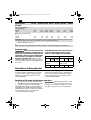
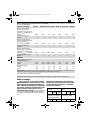
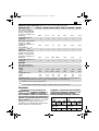
Emission values for sound and vibration (Two-figure – specifications as per ISO 4871)
WARNING
WARNING
WARNING
Sound emission BLS1.6E BLS2.5E BLS3.5 BLS4.2 BSS1.6E BSS1.6CE BSS2.0E
A-weighted emission
pressure power level
measured at the work-
place
L
pA
(re 20 μPa), in
decibels 82.5 81.7 86 87 81.1 81.1 76.2
Measuring uncertainty
K
pA
, in decibels 3 3 3 3 3 3 3
Measured A-weighted
sound power level
L
wA
(re 1 pW), in decibels 93.5 92.7 97 98 92.1 92.1 87.2
Measuring uncertainty
K
wA
, in decibels 3 3 3 3 3 3 3
C-weighted peak sound
pressure level measured
at the workplace
L
pCpeak
,
in decibels 94.9 93.8 103 103.1 93.3 93.3 91
Measuring uncertainty
K
pCpeak
, in decibels 3 3 3 3 3 3 3
OBJ_BUCH-0000000109-001.book Page 5 Friday, June 7, 2013 10:26 AM

6
en
Extension cable.
If the use of an extension cord
is required, its length and con-
ductor cross-section must be adequate for the
application in order to prevent a voltage drop
in the extension cord, power loss and over-
heating of the power tool. Otherwise, the
extension cable and power tool are prone to
electrical danger, and the working efficiency is
decreased.
Recommended dimensions of extension cords
at an operating voltage of 120 V – single-
phase a. c., with only BLS, BSS connected:
Intended use of the power tool:
BLS: Hand-guided sheet metal shears for cut-
ting sheet metal in weather-protected envi-
ronments without water supply using the
application tools and accessories recom-
mended by FEIN.
BSS: Hand-guided slitting shears for cutting
sheet metal and tight curves in weather-pro-
tected environments without water supply
using the application tools and accessories
recommended by FEIN.
Operation of the power tool off power generators.
This power tool is also suitable for use
with AC generators with sufficient power
output that correspond to the Standard
ISO 8528, design type G2. This Standard is
particularly not complied with when the so-
called distortion factor exceeds 10 %. When
in doubt, please refer to the generator
instruction/specification guide.
Operating the power tool off
power generators whose no-
load speed exceeds the voltage value on the
type plate of the power tool is prohibited.
Vibrations
Vibrational emission
value (nibbling)
– m/s
2
– ft/s
2
4.1
13.4
4.8
15.6
12.1
39.57
22.6
73.96
5.7
18.6
5.7
18.6
10.8
35.2
Measuring uncertainty
K
,
in
– m/s
2
– ft/s
2
1.5
4.9
1.5
4.9
1.5
4.9
1.5
4.9
1.5
4.9
1.5
4.9
1.5
4.9
REMARK: The sum of the measured emission value and respective measuring inaccuracy rep-
resents the upper limit of the values that can occur during measuring.
Wear hearing protection!
Measured values determined in accordance with the corresponding product standard.
Sound emission BLS1.6E BLS2.5E BLS3.5 BLS4.2 BSS1.6E BSS1.6CE BSS2.0E
WARNING
Max. cable length, ft Max. cable length, m
≤ 100 100
–200
200
–300
≤ 30 30
– 60
60
–100
Min. conductor size
A.W.G.
Min. conductorcross-
section, mm
2
16 14 12 1.5 2.5 4
WARNING
OBJ_BUCH-0000000109-001.book Page 6 Friday, June 7, 2013 10:26 AM

7
en
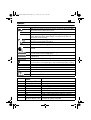
Symbols.
Symbol, character Explanation
Make sure to read the enclosed documents such as the Instruction Man-
ual and the General Safety Instructions.
Observe the instructions in the text or graphic opposite!
Before commencing this working step, pull the power plug out of the-
socket. Otherwise there will be danger of injury if the power tool
should start unintentionally.
Use eye protection during operation.
Use ear protection during operation.
Use protective gloves during operation.
This symbol confirms the certification of this product for the USA and
Canada.
This sign warns of a directly imminent, dangerous situation. A false reac-
tion can cause a severe or fatal injury.
This sign indicates a possible dangerous situation that could cause severe
or fatal injury.
This sign warns of a possible dangerous situation that could cause injury.
Worn out power tools and other electrotechnical and electrical prod-
ucts should be sorted separately for environmentally-friendly recycling.
Product with double or reinforced insulation
~ or a. c. Alternating current
1~ Alternating current, single-phase
Low stroke
Medium stroke
High stroke
DANGER
WARNING
CAUTION
Character Unit of measurement,
national
Explanation
n
0
rpm; /min; min
-1
; r/min Stroke rate at no-load
P
W Electrical power
°Angle width
U V Electric voltage
f Hz Frequency
I
A Electric current intensity
m
kg, lbs Mass
l ft, in Length, width, height, depth, diameter or thread
Ø
ft, in Diameter of a round part
m, s, kg, A, mm, V, W,
Hz, N, °C, dB, min, m/s
2
Basic and derived units of measurement from the
international system of units SI.
OBJ_BUCH-0000000109-001.book Page 7 Friday, June 7, 2013 10:26 AM

8
en
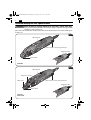
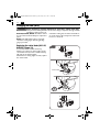
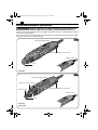
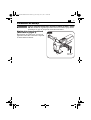
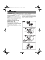
Technical description and specifications.
Before mounting or replacing cutting tool or accessories, pull the power plug.
This preventive safety measure rules out the danger of injuries through acciden-
tal starting of the power tool.
All accessories described or shown in this instruction manual will not be included with your-
power tool.
WARNING
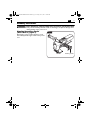
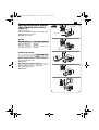
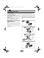
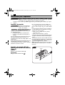
Cutter blade
Dial control for stroke rate preselection
On/off switch
Gripping surface
BSS2.0E
Fig.1
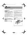
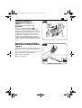
Cutter blade
Dial control for stroke rate preselection
On/off switch
Chip cutter
Gripping surface
BSS1.6E
BSS1.6CE
Chip-cutter actuator
Fig.2
OBJ_BUCH-0000000109-001.book Page 8 Friday, June 7, 2013 10:26 AM

9
en
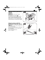
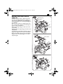
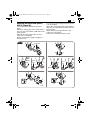
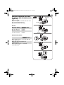
Cutter blade
Dial control for stroke
rate preselection
On/off switch
Gripping surface
BLS1.6E
BLS2.5E
BLS3.5
BLS4.2
BLS1.6E
BLS2.5E
BLS3.5
BLS4.2
Gripping surface
Fig.3
Type BLS1.6E BLS2.5E BLS3.5 BLS4.2 BSS1.6 E BSS1.6CE BSS2.0E
Order number 7 230 34 7 230 35 7 230 23 7 230 24 7 230 31 7 230 32 7 230 33
Current consumption
3.6 A 3.6 A 10.5 A 10.5 A 3.6 A 3.6 A 3.6 A
Power input 350 W 350 W 1200 W 1200 W 350 W 350 W 350 W
Output 210 W 210 W 750 W 750 W 210 W 210 W 210 W
Stroke rate at no-load 2300–4800
/min
800–1700
/min 1700 /min 750 /min
2100–4500
/min
2100–4500
/min
1300–2600
/min
Cutting speed 8–12 m/min 3–6 m/min 4–5 m/min 4–5 m/min 6–10 m/min6–10 m/min 2–4 m/min
Max. work-piece thick-
ness for steel with up to
400 N/mm
2
1/16 in
1.6 mm
3/32 in
2.5 mm
1/8 in
3.5 mm
5/32 in
4.2 mm – – –
Max. work-piece thick-
ness for steel with up to
600 N/mm
2
1/16 in
1.2 mm
3/32 in
2.0 mm
1/8 in
3.0 mm
1/8 in
2.8 mm
– – –
Max. work-piece thick-
ness for steel with up to
800 N/mm
2
3/64 in
1.0 mm
1/16 in
1.6 mm
3/32 in
2.0 mm
3/32 in
2.0 mm – – –
Max. work-piece thick-
ness for aluminium with
up to 250 N/mm
2
3/32 in
2.0 mm
1/8 in
3.0 mm
5/32 in
4.0 mm
3/16 in
5.0 mm
– – –
Min. inside curve radius
19/32 in
15 mm
3/4 in
20 mm
1 3/16 in
30 mm
1 in
25 mm – – –
Max. work-piece thick-
ness for steel with up to
400 N/mm
2
Cutting blade, straight – – – –
1/16 in
1.6 mm
1/16 in
1.6 mm
3/32 in
2.0 mm
OBJ_BUCH-0000000109-001.book Page 9 Friday, June 7, 2013 10:26 AM

10
en
Max. work-piece thick-
ness for steel with up to
600 N/mm
2
Cutting blade, straight – – – –
1/16 in
1.2 mm
1/16 in
1.2 mm
1/16 in
1.5 mm
Max. work-piece thick-
ness for steel with up to
800 N/mm
2
Cutting blade, straight – – – –
1/32 in
0.8 mm
1/32 in
0.8 mm
1/16 in
1.3 mm
Max. work-piece thick-
ness for aluminium with
up to 250 N/mm
2
Cutting blade, straight – – – –
3/32 in
2.0 mm
3/32 in
2.0 mm
1/8 in
3.0 mm
Max. work-piece thick-
ness for steel with up to
400 N/mm
2
Cutting blade, curves – – – –
3/64 in
1.0 mm
3/64 in
1.0 mm
–
Max. work-piece thick-
ness for steel with up to
600 N/mm
2
Cutting blade, curves – – – –
1/32 in
0.8 mm
1/32 in
0.8 mm –
Max. work-piece thick-
ness for aluminium with
up to 250 N/mm
2
Cutting blade, curves – – – –
1/16 in
1.2 mm
1/16 in
1.2 mm –
Min. inside curve radius
Cutting blade, straight – – – –
3 5/8 in
90 mm
3 5/8 in
90 mm
8 in
200 mm
Min. inside curve radius
Cutting blade, curves
– – – –
1 3/16 in
30 mm
1 3/16 in
30 mm
–
Diameter of pilot-drill for
inside cut-outs
Cutting blade, straight – – – –
19/32 in
15 mm
19/32 in
15 mm
1/2 in
12 mm
Diameter of pilot-drill for
inside cut-outs
Cutting blade, curves
– – – –
5/16 in
8 mm
5/16 in
8 mm –
Weight according to
EPTA-Procedure
01/2003
3.74 lbs
(1.7 kg)
4.84 lbs
(2.2 kg)
11.88 lbs
(5.4 kg)
11.44 lbs
(5.2 kg)
3.08 lbs
(1.4 kg)
3.3 lbs
(1.5 kg)
3.74 lbs
(1.7 kg)
Class of protection /II /II /II /II /II /II /II
Type BLS1.6E BLS2.5E BLS3.5 BLS4.2 BSS1.6 E BSS1.6CE BSS2.0E
OBJ_BUCH-0000000109-001.book Page 10 Friday, June 7, 2013 10:26 AM

11
en
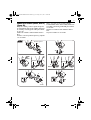
Assembly instructions.
Before mounting or replacing cutting tool or accessories, pull the power plug.
This preventive safety measure rules out the danger of injuries through acci-
dental starting of the power tool.
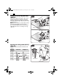
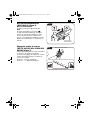
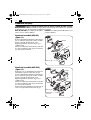
Mounting the auxiliary handle
(BLS3.5/BLS4.2) (figure 4).
Depending on the working manner, screw
the auxiliary handle right or left on the power
tool.
WARNING
1.
2.
Auxiliary handle
Fig.4
OBJ_BUCH-0000000109-001.book Page 11 Friday, June 7, 2013 10:26 AM

12
en
Working instructions.
Before mounting or replacing cutting tool or accessories, pull the power plug.
This preventive safety measure rules out the danger of injuries through acciden-
tal starting of the power tool.
For each job, use only the FEIN application tool released and intended for the respective
application.
Switching on and off.
Check the power supply cable
and the plug for damage.
Always hold the power tool
firmly. Otherwise, you could
lose control over the power tool.
Guide the power tool toward the work
piece only when switched on.
While cutting, hold the power tool as upright
as possible to the work-piece surface
(BLS 1.6 E and BLS 2.5 E).
Guide the power tool uniformly and with
light feed in the cutting direction. Excessive
feed considerably reduces the tool life of the
application tools.
Do not cut steel sheets where welded. Do
not cut layered sheets exceeding the max.
work-piece thickness.
To increase the tool life of the blades, it is rec-
ommended to apply a lubricating agent along-
side the intended cutting line:
– For cuts in steel sheet: Use cutting paste or
cutting oil.
– For cuts in aluminum: Use petroleum.
Do not switch the power tool off until after
having removed it from the cutting path.
The symptom for worn blades is a clearly
increased feed force at lower working prog-
ress.
BSS: For inside cuts, a pilot hole is required;
see “Technical Data”.
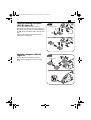
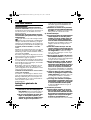
Switching on and off (BLS1.6E,
BLS2.5E, BSS1.6E, BSS1.6CE, BSS2.0E)
(figure 5).
Switching on:
Push the switch toward the front (I).
Switching off:
Push the switch toward the rear ().
WARNING
WARNING
CAUTION
On/off switch
Fig.5
OBJ_BUCH-0000000109-001.book Page 12 Friday, June 7, 2013 10:26 AM

13
en
Switching on and off (BLS3.5/BLS4.2)
(figure 6).
Switching on:
Push the switch toward the front (I).
Switching off:
Press the switch downward ().
The self-start prevention lock prevents the
power tool from automatically restarting
again, even after a brief interruption of the
power supply, e. g., from a pulled mains plug.
Switch the power tool off and then on again.
Setting the stroke rate (BLS1.6E,
BLS2.5E, BSS1.6E, BSS1.6CE, BSS2.0E)
(figure 7).
Set the required stroke rate according to the
material being worked.
The stroke rate can be preset in 6 steps with
the control knob for continuously variable
stroke adjustment.
Level 6: Steel and aluminum.
Level 1 – 6: Plastic.
On/off switch
Fig.6
1–5
1
2
3
4
5
6
Stroke rate preselection
Fig.7
OBJ_BUCH-0000000109-001.book Page 13 Friday, June 7, 2013 10:26 AM

14
en
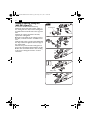
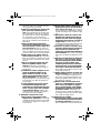
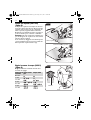
Clipping off the cut chip (BSS1.6CE)
(figure 8).
Clip off the chip by turning the chip-cutter
actuator (3/4 turn in clockwise direction)
while the machine is running. To continue
working, reset the chip-cutter actuator to the
starting position.
Note: Do not continue to work with a broken
off chip brake! Replace the chip cutter.
For cut-outs, pull the power tool from the
chip while the motor is running. Cut long
chips off.
Adjusting the cutting stroke (BLS3.5)
(figure 9).
Adjust the desired clearance with the dial
control.
1.
2.
3.
4.
Chip cutter
Fig.8
Chip-cutter actuator
Material
thickness
Curved cut Straight cut
0.5 mm
1 mm –
1.5 mm –
2 mm –
2.5 mm –
3 mm
3.5 mm
Dial control
Cutter blade
Fig.9
OBJ_BUCH-0000000109-001.book Page 14 Friday, June 7, 2013 10:26 AM

15
en
Adjusting the cutter-blade clearance
(BLS1.6E, BLS2.5E, BLS3.5, BLS4.2)
(figure 10).
Loosen the screw.
Adjust the desired clearance between cutter
blades with the set screw.
Retighten the screw.
BLS1.6E
BLS2.5E, BLS3.5, BLS4.2
Material thickness Cutter-blade clearance
0.3 mm– 0.6 mm 0.1 mm
0.8 mm– 1.2 mm 0.2 mm
1.3 mm– 1.6 mm 0.3 mm
Cutter-blade clear-
ance
Max. work-piece thick-
ness for steel with up to
400 N/mm
2
0.1 mm– 0.2 mm
Min. inside curve radius 0.2 mm
Max. work-piece thick-
ness for steel with up to
800 N/mm
2
> 0.2 mm
7.
5.
3.
2.
6.
4.
1.
Cutter blade
Set screw
Screw
Fig.10
8.
OBJ_DOKU-0000003193-001.fm Page 15 Friday, June 7, 2013 11:05 AM

16
en
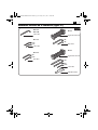
Changing the tool(BSS).
Before mounting or replacing cutting tool or accessories, pull the power plug.
This preventive safety measure rules out the danger of injuries through acciden-
tal starting of the power tool.
BSS1.6E, BSS1.6CE: Cutter blades and cutting
bars cannot be reground.
BSS2.0E: Cutter blades and cutting bars can be
reground.
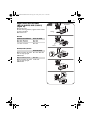
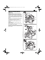
Replacing cutter blades (BSS1.6E)
(figure 11).
Press the engaged supporting pin out in lateral
direction until the cutter blade can be
removed.
Pull the cutter blade out of the cutter head.
Lightly grease the supporting pin and the new
cutter blade.
Insert the new cutter blade. Slide the support-
ing pin through the hole of the cutter blade
until it engages.
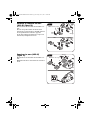
Replacing cutter blades (BSS1.6CE)
(figure 12).
Remove one of the two retaining rings from
the supporting pin using a screw driver.
Press the engaged supporting pin out in lateral
direction until the cutter blade can be
removed.
Pull the cutter blade out of the cutter head.
Lightly grease the supporting pin and the new
cutter blade.
Insert the new cutter blade. Slide the support-
ing pin through the hole of the cutter blade
until it engages.
Reinsert the retaining ring into the corre-
sponding groove of the supporting pin.
WARNING
Cutter blade
Supporting pin
2.
5.
3.
4.
1.
6.
4.
4.
Fig.11
2.
1.
8.
3.
6.
7.
5.
4.
5.
5.
Cutter blade
Supporting pin
Retaining ring
Fig.12
OBJ_BUCH-0000000109-001.book Page 16 Friday, June 7, 2013 10:26 AM

17
en
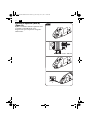
Replacing cutter blades (BSS2.0E)
(figure 13).
For stationary operation, clamp the power
tool in a vice using aluminum or plastic pro-
tection jaws. Tighten the vice adequately so
that the application tool is clamped firmly yet
not damaged.
Remove one of the two retaining rings and
the corresponding washer from the support-
ing pin using a screwdriver.
Pull out the supporting pin and remove the
cutter blade.
Lightly grease the supporting pin and the new
cutter blade.
Insert the new cutter blade. Slide the support-
ing pin through the hole of the cutter blade.
Mount the washer and reinsert the retaining
ring into the corresponding groove of the
supporting pin.
2.
1.
3.
Cutter blade
Supporting pin
Washer
Retaining ring
5.
5.
4.
6.
8.
9.
7.
5.
Fig.13
OBJ_BUCH-0000000109-001.book Page 17 Friday, June 7, 2013 10:26 AM

18
en
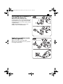
Adjusting the clearance (BSS2.0E)
(figure 14).
Using a hex key, adjust the clearance between
cutter blade and cutting bars.
Make sure that the clearance is equal on both
sides.
2.
3.
5.
4.
aa
1.
a = 0.1 - 0.15 mm
Fig.14
OBJ_BUCH-0000000109-001.book Page 18 Friday, June 7, 2013 10:26 AM

19
en
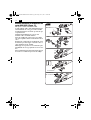
Turning or replacing cutting bars
(BSS1.6E) (figure 15).
Loosen the screws with the hex key.
When the front half of the cutting edges on
the cutting bars are dull, turn the cutting bars
by 180° and mount them each to the opposite
side.
When both cutting edge halves are dull,
replace the cutting bars.
Replacing cutting bars (BSS2.0E)
(figure 16).
Loosen the screws with the hex key.
Remove the cutting bars and mount new
ones.
1.
1.
3.
2.
4.
3.
2.
4.
5.
5.
Cutting bars
Screws
Fig.15
Cutting bars
Screws
1.
2.
4.
3.
5.
6.
Fig.16
OBJ_BUCH-0000000109-001.book Page 19 Friday, June 7, 2013 10:26 AM

20
en
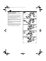
Turning or replacing cutting bars
(BSS1.6CE) (figure 17).
Loosen the screws with the hex key.
When the front half of the cutting edges on
the cutting bars are dull, turn the cutting bars
by 180° and mount them each to the opposite
side.
When both cutting edge halves are dull,
replace the cutting bars.
Bring the cutter blade to the cutting position.
For this, rotate the actuator clockwise a 3/4
turn.
Slide the chip cutter onto the cutter head until
the chip cutter faces against the front edge of
the cutter blade.
Hold the chip cutter and the cutting bars in
this position and fasten them with the screws.
Return the cutter blade back to the working
position by rotating the actuator counter-
clockwise.
Cutting bars
Chip cutter
Screws
5.
1.
3.
2.
4.
3.
2.
4.
8.
7.
1.
6.
Chip-cutter
actuator
Fig.17
OBJ_BUCH-0000000109-001.book Page 20 Friday, June 7, 2013 10:26 AM
Page is loading ...
Page is loading ...
Page is loading ...
Page is loading ...
Page is loading ...
Page is loading ...
Page is loading ...
Page is loading ...
Page is loading ...
Page is loading ...
Page is loading ...
Page is loading ...
Page is loading ...
Page is loading ...
Page is loading ...
Page is loading ...
Page is loading ...
Page is loading ...
Page is loading ...
Page is loading ...
Page is loading ...
Page is loading ...
Page is loading ...
Page is loading ...
Page is loading ...
Page is loading ...
Page is loading ...
Page is loading ...
Page is loading ...
Page is loading ...
Page is loading ...
Page is loading ...
Page is loading ...
Page is loading ...
Page is loading ...
Page is loading ...
Page is loading ...
Page is loading ...
Page is loading ...
Page is loading ...
Page is loading ...
Page is loading ...
Page is loading ...
Page is loading ...
Page is loading ...
Page is loading ...
Page is loading ...
Page is loading ...
Page is loading ...
Page is loading ...
Page is loading ...
Page is loading ...
Page is loading ...
-
 1
1
-
 2
2
-
 3
3
-
 4
4
-
 5
5
-
 6
6
-
 7
7
-
 8
8
-
 9
9
-
 10
10
-
 11
11
-
 12
12
-
 13
13
-
 14
14
-
 15
15
-
 16
16
-
 17
17
-
 18
18
-
 19
19
-
 20
20
-
 21
21
-
 22
22
-
 23
23
-
 24
24
-
 25
25
-
 26
26
-
 27
27
-
 28
28
-
 29
29
-
 30
30
-
 31
31
-
 32
32
-
 33
33
-
 34
34
-
 35
35
-
 36
36
-
 37
37
-
 38
38
-
 39
39
-
 40
40
-
 41
41
-
 42
42
-
 43
43
-
 44
44
-
 45
45
-
 46
46
-
 47
47
-
 48
48
-
 49
49
-
 50
50
-
 51
51
-
 52
52
-
 53
53
-
 54
54
-
 55
55
-
 56
56
-
 57
57
-
 58
58
-
 59
59
-
 60
60
-
 61
61
-
 62
62
-
 63
63
-
 64
64
-
 65
65
-
 66
66
-
 67
67
-
 68
68
-
 69
69
-
 70
70
-
 71
71
-
 72
72
-
 73
73


Ask a question and I''ll find the answer in the document
Finding information in a document is now easier with AI
in other languages
- français: FEIN BSS 1.6 CE Manuel utilisateur
- español: FEIN BSS 1.6 CE Manual de usuario
Related papers
-
FEIN FSC 2.0 Q User manual
-
-
-
FEIN GSZ 8-280 PEL User manual
-
-
-
-
FEIN SuperCut FSC 1.7 Q Auto Glass User manual
-
-
Other documents
-
Parkside PES 200 A1 Operation and Safety Notes
-
Bosch GOP 18 V-EC Original Instructions Manual
-
Bosch PKS18LI Owner's manual
-
Ideal 36-311 Installation guide
-
-
-
-
Bosch PSA 700 E Original Instructions Manual
-
Bosch PEX 4000 AE Owner's manual
-