Page is loading ...

Operator’s Manual 1
OPERATOR’S MANUAL FOR
GEN-1100-0MS0
GENERATOR
CAUTION
RISK OF INJURY! READ MANUAL BEFORE OPERATING!
ThIS MANUAL IS AN IMPORTANT PART OF ThE GENERATOR
AND MUST REMAIN wITh ThIS UNIT!
©
Copyright 2006, Mi-T-M
®
Corporation Form #37-0889-E/F/S-010406

2 Operator’s Manual
Introduction
THANK YOU for purchasing a Mi-T-M product.
READ THIS MANUAL carefully to learn how to operate
and service your machine correctly. Failure to do so could
result in personal injury or equipment damage.
THIS MANUAL SHOULD BE CONSIDERED a permanent
part of your machine and should remain with the machine
when you sell it.
MEASUREMENTS in this manual are given in both
metric and customary U.S. unit equivalents. Use only
correct replacement parts and fasteners. Metric and inch
fasteners may require a specic metric or inch wrench.
RIGHT HAND AND LEFT HAND sides are determined by
facing the control panel end of the machine.
The SERIAL NUMBER is located in the Specication or
Identication Numbers section. Accurately record all the
numbers to help in tracing the machine should it be stolen.
Your dealer also needs these numbers when you order
parts. File the identication numbers in a secure place
off the machine.
WARRANTY is provided from your dealer for customers
who operate and maintain their equipment as described
in this manual. The warranty is explained on the warranty
certicate shown in this manual.
This warranty provides you the assurance that your
dealer will back products where defects appear within
the warranty period. Should the equipment be abused,
or modied to change its performance beyond the original
factory specications, the warranty will become void.

Operator’s Manual 3
Introduction
NOTICE
FEDERAL EMISSION COMPONENT DEFECT WARRANTY and CALIFORNIA EMISSION CONTROL WARRANTY
are applicable to only those engines / generators complied with EPA (Environmental Protection Agency) and CARB
(California Air Resources Board) emission regulations in the U.S.A.
NOTICE
To the engines / generators exported to and used in the countries other than the U.S.A., warranty service shall be
performed by the distributor in each country in accordance with the standard Robin engine / generator warranty policy
as applicable.
AIR INDEX
To show compliance with California emission regulations, a hang tag has been provided displaying the Air Index level
and durability period of this engine.
The Air Index level denes how clean an engine’s exhaust is over a period of time. A bar graph scaled from “0” (most
clean) to “10” (least clean) is used to show an engine’s Air Index level. A lower Air Index level represents cleaner
exhaust from an engine.
The period of time (in hours) that the Air Index level is measured is known as the durability period. Depending on the
size of the engine, a selection of time periods can be used to measure the Air Index level (see below).
Descriptive Term Applicable to Emissions Durability Period
Moderate: 50 hours (engine from 0 to 80 cc)
125 hours (engine greater than 80 cc)
Intermediate: 125 hours (engine from 0 to 80 cc)
250 hours (engine greater than 80 cc)
Extended: 300 hours (engine from 0 to 80 cc)
500 hours (engine greater than 80 cc)
Notice: This hang tag must remain on the engine or piece of equipment, and only be removed by the ultimate purchaser
before operation.

4 Operator’s Manual
Introduction
FEDERAL EMISSIONS COMPONENT DEFECT WARRANTY
EMISSIONS COMPONENT DEFECT WARRANTY COVERAGE -- This emission warranty is applicable in all States, except the state of
California.
Fuji Heavy Industries Ltd. and Robin America Inc., Wood Dale Illinois, (herein “ROBIN AMERICA”) warrant(s) to the initial retail purchaser and each
subsequent owner, that this Non-road engine (herein “engine”) has been designed, built, and equipped to conform at the time of initial sale to all
applicable regulations of the U.S.
Environmental Protection Agency (EPA), and that the engine is free of defects in materials and workmanship which would cause this engine to fail
to conform with EPA regulations during its warranty period.
For the components listed under PARTS COVERED, the service dealer authorized by ROBIN AMERICA will, at no cost to you, make the necessary
diagnosis, repair, or replacement necessary to ensure that the engine complies with applicable U.S. EPA regulations.
EMISSIONS COMPONENT DEFECT WARRANTY PERIOD
The warranty period for this engine begins on the date of sale to the
initial purchaser and continues for a period of two years.
PARTS COVERED
Listed below are the parts covered by the Emission Components
Defect Warranty. Some of the parts listed below may require scheduled
maintenance and are warranted up to the rst scheduled replacement
point for that part.
1. Fuel Metering System
a. Carburetor and internal parts (and / or pressure regulator or fuel
injection system).
b. Air / fuel ratio feedback and control system, if applicable.
c. Cold start enrichment system, if applicable.
d. Regulator assembly (gasoline fuel, if applicable).
2. Air Induction System
a. Intake manifold, if applicable.
b. Air lter.
3. Ignition System
a. Spark plugs.
b. Magneto or electronic ignition system.
c. Spark advance / retard system, if applicable.
4. Exhaust manifold, if applicable.
5. Miscellaneous items used in above systems.
a. Electronic controls, if applicable.
b. Hoses, belts, connectors, and assemblies.
c. Filter lock assembly (gaseous fuel, if applicable).
OBTAINING WARRANTY SERVICE
To obtain warranty service, take your engine to the nearest authorized
Robin America. Bring your sales receipts indicating date of purchase
for this engine. The service dealer authorized by ROBIN AMERICA
will perform the necessary repairs or adjustments within a reasonable
amount of time and furnish you with a copy of the repair order. All parts
and accessories replaced under this warranty become the property of
ROBIN AMERICA.
WHAT IS NOT COVERED
Conditions resulting from tampering, misuse, improper adjustment
(unless they were made by the service dealer authorized by ROBIN
AMERICA during a warranty repair), alteration, accident, failure to use
the recommended fuel and oil, or not performing required maintenance
services.
The replacement parts used for required maintenance services.
Consequential damages such as loss of time, inconvenience, loss of
use of the engine or equipment, etc.
Diagnosis and inspection charges that do not result in warranty-eligible
service being performed.
Any non-authorized replacement part, or malfunction of authorized
parts due to use of non-authorized parts.
OWNER’S WARRANTY RESPONSIBILITIES
As the engine owner, you are responsible for the performance of the
required maintenance listed in your owner’s manual. ROBIN AMERICA
recommends that you retain all receipts covering maintenance on
your engine, but ROBIN AMERICA cannot deny warranty solely for
the lack of receipts or for your failure to ensure the performance of all
scheduled maintenance.
As the engine owner, you should however be aware that ROBIN
AMERICA may deny warranty coverage if your engine or a part has
failed due to abuse, neglect, improper maintenance or unapproved
modications.
You are responsible for the presenting your engine to the nearest service
dealer authorized by ROBIN AMERICA when a problem exists.
If you have any questions regarding your warranty rights and
responsibilities, you should contact the ROBIN AMERICA customer
service department at 1-630-350-8200 for the information.
THINGS YOU SHOULD KNOW ABOUT THE EMISSION
CONTROL SYSTEM WARRANTY MAINTENANCE AND
REPAIRS
You are responsible for the proper maintenance of the engine. You
should keep all receipts and maintenance records covering the
performance of regular maintenance in the event questions arise.
These receipts and maintenance records should be transferred to each
subsequent owner of the engine. ROBIN AMERICA reserves the right to
deny warranty coverage if the engine has not been properly maintained.
Warranty claims will not be denied, however, solely because of the lack
of required maintenance or failure to keep maintenance records.
MAINTENANCE, REPLACEMENT OR REPAIR OF EMISSION
CONTROL DEVICES AND SYSTEMS MAY BE PERFORMED BY ANY
REPAIR ESTABLISHMENT OR INDIVIDUAL;
HOWEVER, WARRANTY REPAIRS MUST BE PERFORMED BY
A SERVICE DEALER AUTHORIZED BY ROBIN AMERICA. THE
USE OF PARTS THAT ARE NOT EQUIVALENT IN PERFORMANCE
AND DURABILITY TO AUTHORIZED PARTS MAY IMPAIR THE
EFFECTIVENESS OF THE EMISSION CONTROL SYSTEM AND MAY
HAVE A BEARING ON THE OUTCOME OF A WARRANTY CLAIM.
If other than the parts authorized by ROBIN AMERICA are used for
maintenance replacements or for the repair of components affecting
emission control, you should assure yourself that such parts are
warranted by their manufacturer to be equivalent to the parts authorized
by ROBIN AMERICA in their performance and durability.
HOW TO MAKE A CLAIM
All repair qualifying under this limited warranty must be performed by
a service dealer authorized by ROBIN AMERICA. In the event that
any emission-related part is found to be defective during the warranty
period, you shall notify ROBIN AMERICA customer service department
at 1-630-350-8200 and you will be advised of the appropriate warranty
service dealer or service providers where the warranty repair can be
performed.

Operator’s Manual 5
Introduction
CALIFORNIA EMISSION CONTROL WARRANTY STATEMENT
YOUR WARRANTY RIGHTS AND OBLIGATIONS
The California Air Resources Board and Fuji Heavy Industries Ltd. (herein “FUJI”) are pleased to explain the emission control system warranty on
your 2005 and later Small Off-Road engine (herein “engine”). In California, new engine must be designed, built and equipped to meet the State’s
stringent anti-smog standards. FUJI must warrant the emission control system on your engine for the periods of time described below, provided
there has been no abuse, neglect or improper maintenance of your engine. Your emission control system may include parts such as the carburetor
or fuel-injection system, and the ignition system. Also included may be hoses, belts, connectors and other emission-related assemblies. Where a
warrantable condition exists, ROBIN AMERICA will repair your engine at no cost to you including diagnosis, parts and labor.
MANUFACTURER’S WARRANTY COVERAGE:
The 2005 and later engines are warranted for two (2) years. If any emission related part on your engine is defective, the part will be repaired or
replaced by ROBIN AMERICA.
OWNER’S WARRANTY RESPONSIBILITIES:
- As the engine owner, you are responsible for the performance of the required maintenance listed in your Owner’s Manual. ROBIN AMERICA
recommends that you retain all receipts covering maintenance on your engine, but FUJI cannot deny warranty solely for the lack of receipts or
for your failure to ensure the performance of all scheduled maintenance.
- As the engine owner, you should however, be aware that FUJI may deny you warranty coverage if your engine or a part has failed due to abuse,
neglect, improper maintenance or unapproved modications.
- Your are responsible for presenting your engine to a service dealer or warranty station authorized by ROBIN AMERICA Inc. 940 Lively Blvd.,
Wood Dale, IL 60191 (herein ROBIN AMERICA) as soon as a problem exists. The warranty repairs should be completed in a reasonable amount
of time, not to exceed 30 days.
If you have any questions regarding your warranty rights and responsibilities, you should contact Robin America Inc. Customer Service Department
at 1-630-350-8200.
LIMITED WARRANTY
on Emission Control Systems
- California Only -
FUJI warrants to the owner of the 2005 and later engine that the engine (1) has been designed, built and equipped so as to conform at the time of
manufacture with the applicable regulations of the California Air Resources Board, and (2) is free from defects in materials and workmanship that
could cause it to fail to conform with those regulations as may be applicable in the terms and conditions stated below.
A. COMMENCEMENT DATE
The warranty period begins on the date the engine is delivered to a
rst retail purchaser.
B. LENGTH OF COVERAGE
FUJI warrants to a rst retail purchaser and each subsequent purchaser
that the engine is free from defects in materials and workmanship that
cause the failure of a warranted emission-related part for a period of
two (2) years after the date of delivery to the rst retail purchaser.
C. WHAT IS COVERED
1. REPAIR OR REPLACEMENT PARTS
Repairs and replacement of any warranted part will be performed at
no charge to you by an authorized service dealer or a warranty
station. You may contact the Robin America Inc. Customer Service
Department at 1-630-350-8200 to obtain the name of the nearest
appropriate location where your warranty repairs are performed.
2. WARRANTY PERIOD
This warranty continues for a period of two (2) years and applies
only to the repair, replacement or adjustment of the component
parts that are not scheduled for replacement as required
maintenance. Further, component parts which are scheduled only
for regular inspection to the effect of “repair or replace as
necessary” are warranty for the warranty period. Any warranted
part which is scheduled for replacement as required
maintenance is warranted for the period of time up to the rst
scheduled replacement point for that part.
3. DIAGNOSIS
You will not be charged for diagnostic labor that leads to the
determination that a warranted part is defective, if the diagnostic
work is performed at an authorized service dealer or warranty
station.
4. DAMAGES
If a warranted part failed causing damage to the engine
components, consult an warranty station.
D. WHAT IS NOT COVERED
1. This limited warranty does not cover any part which malfunctions,
fails or is damaged due to failure to follow the maintenance and
operating instructions set forth in the 2005 and later Owner’s Manual
including:
a. Improper maintenance of any warranted parts.
b. Improper installation, adjustment or repair of the engine or of
any warranted part unless performed by an authorized service
dealer.
c. Failure to follow recommendations on fuel use contained in the
2005 and later Owner’s Manual.
d. Repairs performed outside of the authorized warranty service
dealers.
e. Use of parts which are not authorized by FUJI.
2. Add-on or modied parts.
This warranty does not cover any part that malfunctions, fails or is
damaged due to alterations by changing, adding to or removing
parts from the engine.
3. Expenses incurred by processing warranty-claims.
FUJI, any authorized service dealer and warranty station
shall not be liable for any loss of use of the engine, for any
alternative usage, for any damage to goods, loss of time or
inconvenience.
E. HOW TO FILE A CLAIM
All repairs qualifying under this Limited Warranty must be performed
by a dealer who sold you the engine or warranty station authorized by
ROBIN AMERICA. In the event that any emission-related part is found
to be defective during the warranty period, you must notify the Robin
America Inc. Customer Service Department at 1-630-350-8200 and
you will be advised of the appropriate warranty service facilities where
the warranty repair is to be performed.

6 Operator’s Manual
Introduction
F. WHERE TO OBTAIN WARRANTY SERVICE
It is recommended that warranty service be performed by the authorized
dealer who sold you the engine, although warranty service will be
performed by any authorized service dealers or warranty stations
anywhere in the United States.
When warranty repair is needed, the engine must be brought to an
authorized service dealer or warranty station’s place of business during
normal business hours. In all cases, a reasonable time, not to exceed
30 days, must be allowed for the warranty repair to be completed after
the engine is received by the authorized service dealer or warranty
station.
G. MAINTENANCE, REPLACEMENT AND REPAIR OF
EMISSION-RELATED PARTS
Only warranted engine replacement parts approved by FUJI should
be used in the performance of any warranty maintenance or repairs
on emission-related parts. If other than authorized parts are used for
maintenance, replacement or repair of components affecting emission
control, you should assure yourself that such parts are warranted by
their manufacturer to be equivalent to authorized parts in performance
and durability. FUJI, however, assumes no liability under this warranty
with respect to parts other than authorized parts. The use of non-
authorized replacement parts does not invalidate the warranty on
other components unless the non-authorized parts cause damage to
warranted parts.
H. PARTS COVERED UNDER THE CALIFORNIA EMISSIONS
WARRANTY
1. Fuel Metering System
a. Carburetor and internal parts (and / or pressure regulator or fuel,
injection system).
b. Air / fuel ratio feedback and control system, if applicable.
c. Cold start enrichment system, if applicable.
d. Regulator assembly (gaseous fuel, if applicable).
2. Air Induction System
a. Intake manifold, if applicable.
b. Air lter.
3. Ignition System
a. Spark Plug.
b. Magneto or electronic ignition system.
c. Spark advance / retard system, if applicable.
4. Exhaust manifold, if applicable.
5. Miscellaneous items used in above systems.
a. Electronic controls, if applicable.
b. Hoses, belts, connectors, and assemblies.
c. Filter lock assembly (gaseous fuel, if applicable).
I. MAINTENANCE STATEMENTS
It is your responsibility to have all scheduled inspection and maintenance services performed at the times recommended in the 2005 and later
Owner’s Manual and to retain proof that inspection and maintenance services are performed at the times when recommended. FUJI will not deny
a warranty claim solely because you have no record of maintenance; however, FUJI may deny a warranty claim if your failure to perform required
maintenance resulted in the failure of warranted part. The proof which you maintain should be given to each subsequent owner of the engine. You are
responsible for performing the scheduled maintenance described below based on the procedures specied in the 2005 and later Owner’s Manual.
The scheduled maintenance below is based on a normal engine operating schedule.
PROCEDURE: INTERVAL:
1. Change engine oil. 1. Initial 20 hours and every 100 hours afterward.
2. Clean air cleaner (element). 2. Every 50 hours.
3. Replace air cleaner element. 3. Every 200 hours.
4. Clean and adjust spark plug and electrodes. 4. Every 200 hours.
NOTE: More frequent maintenance may be necessary under dusty, dirty or severe conditions.

Operator’s Manual 7
Contents
All information, illustrations and specications in this manual are based
on the latest information available at the time of publication. The right is
reserved to make changes at any time without notice.
Page
Safety ........................................................................ 9
Safety Signs ........................................................... 16
Controls ................................................................. 17
Preparing the Generator ........................................ 20
Operation ................................................................ 25
Troubleshooting ..................................................... 31
Service .................................................................... 32
Storage .................................................................... 36
Specications ......................................................... 37
Wire Diagram ........................................................... 38
Warranty .............................................................39-41
Notes ........................................................................ 42

8 Operator’s Manual
Contents

Operator’s Manual 9
W
A
R
N
I
N
G
W
A
R
N
I
N
G
S
I
N
T
H
E
M
A
N
U
A
L
S
.
W
A
R
N
I
N
G
S
I
N
T
HE
M
A
N
U
A
L
S
.
C
A
U
T
I
O
N
O
C
A
U
T
I
O
N
S
I
N
O
T
H
E
M
A
N
U
A
L
S
O
C
A
U
T
I
O
N
S
I
N
O
T
H
E
M
A
N
U
A
L
S
O
C
A
U
T
I
O
N
S
I
N
O
T
H
E
M
A
N
U
A
L
S
O
C
A
U
T
I
O
N
S
I
N
O
T
H
E
M
A
N
U
A
L
S
Safety
RECOGNIZE SAFETY INFORMATION
This is the safety alert symbol. When you see this symbol
on your machine or in this manual, be alert to the potential
for personal injury.
Follow recommended precautions and safe operating
practices.
UNDERSTAND SIGNAL WORDS
A signal word--DANGER, WARNING or CAUTION--is used
with the safety-alert symbol. DANGER identies the most
serious hazards.
DANGER or WARNING safety signs are located near
specific hazards. General precautions are listed on
CAUTION safety signs. CAUTION also calls attention to
safety messages in this manual.
FOLLOW SAFETY INSTRUCTIONS
Carefully read all safety messages in this manual and
safety signs on your machine. Keep safety signs in good
condition. Replace missing or damaged safety signs.
Be sure new equipment components and repair parts
include the current safety signs. Replacement safety
signs are available from your Mi-T-M Customer Service
Representative.
Learn how to operate the machine and how to use controls
properly. Do not let anyone operate without instruction.
Keep your machine in proper working condition.
Unauthorized modications to the machine may impair the
function and/or safety and affect machine life.
If you do not understand any part of this manual and
need assistance, contact your Mi-T-M Customer Service
Representative.

10 Operator’s Manual
CARBON MONOXIDE - POISONOUS GAS
Use generator outdoors, away from open windows, vents, or
doors. Keep generator at least 1 meter (3 feet) away from any
structure or building during use.
Generator exhaust contains carbon monoxide - a poisonous
gas that can kill you. You CAN NOT smell or see this gas.
Never use a generator in enclosed or partially-enclosed spaces.
Generators can produce high levels of carbon monoxide very
quickly. When you use a portable generator, remember that you
cannot smell or see carbon monoxide. Even if you can’t smell
exhaust fumes, you may still be exposed to carbon monoxide.
If you start to feel sick, dizzy, or weak while using a generator, get
to fresh air RIGHT AWAY. DO NOT DELAY. The carbon monoxide
from generators can rapidly lead to full incapacitation and death.
If you experience serious symptoms, get medical attention
immediately. Inform medical staff that carbon monoxide poisoning
is suspected. If you experienced symptoms while indoors, have
someone call the re department to determine when it is safe to
re-enter the building.
NEVER operate the generator in an explosive atmosphere, near
combustible materials or where ventilation is not sufcient to carry
away exhaust fumes. Exhaust fumes can cause serious injury
or death.
NEVER use a generator indoors, including in homes, garages,
basements, crawl spaces, and other enclosed or partially-enclosed
areas, even with ventilation. Opening doors and windows or using
fans will not prevent carbon monoxide build-up in the home.
Follow the instructions that come with your generator. Locate the
unit outdoors and away from doors, windows, and vents that could
allow the carbon monoxide gas to come indoors.
ONLY run generator outdoors and away from air intakes.
NEVER run generator inside homes, garages, sheds, or other
semi-enclosed spaces. These spaces can trap poisonous gases
EVEN IF you run a fan or open doors and windows.
If you start to feel sick, dizzy, or weak while using the generator,
shut if off and get fresh air RIGHT AWAY. See a doctor. You may
have carbon monoxide poisoning.
Install battery-operated carbon monoxide alarms or plug-in carbon
monoxide alarms with battery back-up in your home, according to
the manufacturer’s installation instructions. The carbon monoxide
alarms should be certied to the requirements of the latest safety
standards for carbon monoxide alarms. (UL 2034, IAS 6-96, or
CSA 6.19.01).
Test your carbon monoxide alarm frequently and replace dead
batteries.

Operator’s Manual 11
SAFETY WARNING WHEN REFUELING
Gasoline is extremely ammable and its vapors can explode if
ignited.
Observe all safety regulations for the safe handling of fuel. Handle
fuel in safety containers. If the container does not have a spout, use
a funnel.
Do not overll the fuel tank, leave room for the fuel to expand.
Do not rell fuel tank while the engine is running. Before refueling
the generator, turn it off and let it cool down. Gasoline spilled on hot
engine parts could ignite.
Fill the tank only on an area of bare ground. While fueling the tank,
keep heat, sparks and open ame away. Carefully clean up any
spilled fuel before starting engine.
Always ll fuel tank in an area with plenty of ventilation to avoid
inhaling dangerous fumes.
NEVER store fuel for your generator in the home. Gasoline, propane,
kerosene, and other ammable liquids should be stored outside of living
areas in properly-labeled, non-glass safety containers. Do not store
them near a fuel-burning appliance, such as a natural gas water heater
in a garage. If the fuel is spilled or the container is not sealed properly,
invisible vapors from the fuel can travel along the ground and can be
ignited by the appliance’s pilot light or by arcs from electric switches
in the appliance.
GROUND FAULT CIRCUIT INTERRUPTER PROTECTION
These generators are equipped with a GFCI (Ground Fault Circuit
Interrupters) 120V duplex receptacles for protection against the hazards
of electrical shock from defective attachments such as, tools, cords,
and cables.
WARNING: The GFCI may not function unless the
ge nerat or is pr ope rl y g round ed. Foll ow
the correct procedure specified in the section
labeled “GROUNDING INSTRUCTIONS”.
A GFCI is a device that interrupts electricity from either the utility or
generator by means of a special type of circuit breaker if a fault current
ow to the ground occurs.
A GFCI can be used only with generators that have the neutral wire
internally bonded to the frame, and the frame properly grounded to the
earth. A GFCI will not work on generators that do not have the neutral
wire bonded to the frame, or on generators which have not been properly
grounded. All Mi-T-M generators have internally bonded ground wires.
A GFCI will not work if the unit is not properly grounded.
A GFCI may be required by OSHA regulations, the National Electric
Code and/or local and federal codes when operating a generator.
For additional protections against shock hazards due to defective
equipment attached to the twist-lock receptacles, consider the use of
a GFCI on each of these receptacles as well.
GFCI and GFCI protected cord sets and cables may be purchased from
local electrical supply houses.

12 Operator’s Manual
ELECTRICAL HAZARDS
This product must be grounded. If it should malfunction or breakdown,
grounding provides a path of least resistance for electric current to
reduce the risk of electric shock.
DANGER - IMPROPER CONNECTION OF THE EQUIPMENT-
GROUNDING CONDUCTOR CAN RESULT IN A RISK OF
ELECTROCUTION. CHECK WITH A QUALIFIED
ELECTRICIAN OR SERVICE PERSON IF YOU ARE IN
DOUBT AS TO WHETHER THE UNIT IS PROPERLY
GROUNDED.
This generator is equipped with a grounding terminal for your
protection. Always complete the ground path from the generator to an
external ground source as instructed in the section labeled “Grounding
Instructions” in the Preparation section of this manual.
The generator is a potential source of electrical shock if not kept dry.
Keep the generator dry and do not use in rain or wet conditions. To
protect from moisture, operate it on a dry surface under an open,
canopy-like structure. Dry your hands if wet before touching the
generator.
Plug appliances directly into the generator. Or, use a heavy duty,
outdoor-rated extension cord that is rated (in watts or amps) at least
equal to the sum of the connected appliance loads. Check that the
entire cord is free of cuts or tears and that the plug has all three prongs,
especially a grounding pin.
NEVER try to power the house wiring by plugging the generator into
a wall outlet, a practice known as “back feeding”. This is an extremely
dangerous practice that presents an electrocution risk to utility workers
and neighbors served by the same utility transformer. It also bypasses
some of the built-in household circuit protection devices.
If you must connect the generator to the house wiring to power
appliances, have a qualied electrician install the appropriate equipment
in accordance with local electrical codes. Or, check with your utility
company to see if it can install an appropriate power transfer switch.
For power outages, permanently installed stationary generators are
better suited for providing backup power to the home. Even a properly
connected portable generator can become overloaded. This may result
in overheating or stressing the generator components, possibly leading
to a generator failure.

Operator’s Manual 13
IMPORTANT SAFETY INSTRUCTIONS
WARNING: To reduce the risk of injury, read this operator’s
manual completely before using. When using this
product, the following basic precautions should always
be followed:
1. Read all the instructions before using the product.
2. Do not enclose the generator nor cover it with a box. The
generator has a built-in forced air cooling system, and may
become overheated if it is enclosed. If generator has been
covered to protect if from the weather during non use,
be sure to remove it and keep it well away from the area
during generator use.
3. Operate the generator on a level surface. It is not
necessary to prepare a special foundation for the generator.
However, the generator will vibrate on an irregular surface,
so choose a level place without surface irregularities.
If the generator is tilted or moved during operation, fuel
may spill and/or the generator may tip over, causing a
hazardous situation.
Proper lubrication cannot be expected if the generator is
operated on a steep incline or slope. In such a case, piston
seizure may occur even if the oil is above the upper level.
4. Pay attention to the wiring or extension cords from the
generator to the connected device. If the wire is under
the generator or in contact with a vibrating part, it may
break and possibly cause a re, generator burnout, or
electric shock hazard. Replace damaged or worn cords
immediately.
5. Do not operate in rain, in wet or damp conditions, or with
wet hands. The operator may suffer severe electric shock if
the generator is wet due to rain or snow.
6. If wet, wipe and dry it well before starting. Do not pour
water directly over the generator, nor wash it with water.
7. Be extremely careful that all necessary electrical grounding
procedures are followed during each and every use. Failure
to do so can be fatal.
8. NEVER try to power the house wiring by plugging the
generator into a wall outlet, a practice known as “back
feeding”. This is an extremely dangerous practice that
presents an electrocution risk to utility workers and
neighbors served by the same utility transformer. It also
bypasses some of the built-in household circuit protection
devices.
If you must connect the generator to the house wiring to
power appliances, have a qualied electrician install the
appropriate equipment in accordance with local electrical
codes. Or, check with your utility company to see if it can
install an appropriate power transfer switch.
9. No smoking while charging a battery. The battery emits
ammable hydrogen gas, which can explode if exposed to
electric arcing or open ame. Keep the area well-ventilated
and keep open ames / sparks away when charging a
battery.
W
A
R
N
I
N
G
W
A
R
N
I
N
G
S
I
N
T
H
E
M
A
N
U
A
L
S
.
W
A
R
N
I
N
G
S
I
N
T
H
E
M
A
N
U
A
L
S
.
C
A
U
T
I
O
N
O
C
A
U
T
I
O
N
S
I
N
O
T
H
E
M
A
N
U
A
L
S
O
C
A
U
T
I
O
N
S
I
N
O
T
H
E
M
A
N
U
A
L
S
O
C
A
U
T
I
O
N
S
I
N
O
T
H
E
M
A
N
U
A
L
S
O
C
A
U
T
I
O
N
S
I
N
O
T
H
E
M
A
N
U
A
L
S

14 Operator’s Manual
IMPORTANT SAFETY INSTRUCTIONS
10. Engine becomes extremely hot during and for some time
after operation. Keep combustible materials well away
from generator area. Be very careful not to touch any
parts of the hot engine especially the mufer area or
serious burns may result.
11. Keep children and all bystanders at a safe distance from
work area.
12. It is absolutely essential that you know the safe and
proper use of the power tool or appliance that you intend
to use. All operators must read, understand and follow
the tool / appliance owners manual. Tool and appliance
applications and limitations must be understood. Follow
all directions given on labels and warnings. Keep all
instruction manuals and literature in a safe place for
future reference.
13. Use only “LISTED” extension cords. When a tool or
appliance is used outdoors, use only extension cords
marked “For Outdoor Use”. Extension cords, when not in
use should be stored in a dry and well ventilated area.
14. Always disconnect tools or appliances when not in use,
before servicing, adjusting, or installing accessories and
attachments.
SAVE THESE INSTRUCTIONS
W
A
R
N
I
N
G
W
A
R
N
I
N
G
S
I
N
T
H
E
M
A
N
U
A
L
S
.
W
A
R
N
I
N
G
S
I
N
T
H
E
M
A
N
U
A
L
S
.
C
A
U
T
I
O
N
O
C
A
U
T
I
O
N
S
I
N
O
T
H
E
M
A
N
U
A
L
S
O
C
A
U
T
I
O
N
S
I
N
O
T
H
E
M
A
N
U
A
L
S
O
C
A
U
T
I
O
N
S
I
N
O
T
H
E
M
A
N
U
A
L
S
O
C
A
U
T
I
O
N
S
I
N
O
T
H
E
M
A
N
U
A
L
S

Operator’s Manual 15
WEAR PROTECTIVE CLOTHING
Wear close fitting clothing and safety equipment
appropriate to the job.
Wear a suitable hearing protective device such as
earmuffs or earplugs to protect against objectionable or
uncomfortable loud noises.
Operating equipment safely requires the full attention of
the operator. Do not wear radio or music headphones while
operating machine.
INSPECT GENERATOR
Be sure all covers, guards and shields are tight and in
place.
Locate all operating controls and safety labels.
Inspect power cord for damage before using. There is a
hazard of electrical shock from crushing, cutting or heat
damage.
PREPARE FOR EMERGENCIES
Keep a rst aid kit and re extinguisher handy.
Keep emergency numbers for doctors, ambulance service,
hospital and re department near your telephone.
Be prepared if a re starts.
SERVICE GENERATOR SAFELY
Before servicing the generator, disconnect all equipment
and allow unit to cool down.
Service generator in a clean dry at area.
Make sure the engine is stopped before starting any
maintenance servicing or repair.

16 Operator’s Manual
SAFETY SIGNS
In accordance with the European requirements (eec Directives), the specied symbols as shown in the following table
are used for the products and this instructions manual.
Read the operator's instruction manual.
Stay clear of the hot surface.
Exhaust gas is poisonous.
Do not operate in an unventilated room.
Stop the engine before refueling.
Fire, open light and smoking
prohibited.
Caution, risk of electric shock.
Do not connect the generator to
the commercial power lines.
HOT, avoid touching the hot areas.
Engine oil
ON
(power and Engine)
Add oil
Battery charging
condition
OFF
(power and Engine)
Alternating current
Direct current
Plus ;
positive polarity
Minus ;
negative polarity
OUT-position of a
bistable push control
IN-position of a
bistable push control
Protective earth
(ground)
Fuse
Choke ;
cold starting aid
Engine start
(Electric start)
Engine stop
Diesel fuel
Fast
Slow
P r
Rated power (kW)
COP
Continuous power
COS
r
Rated power factor
f r
Rated frequency (Hz)
U r
Rated voltage (V)
I r
Rated current (A)
H max
Maximum site altitude
above sea-level (m)
T max
Maximum ambient
temperature ( )
m Mass (kg)
Run
Stop

Operator’s Manual 17
Controls
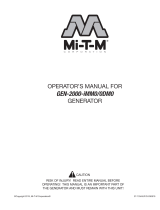
CONTROLS
1-- Recoil Starter
2-- Control Panel
3-- Ground Terminal
4-- Side Panel (L)
5-- Air Cleaner
6-- Fuel Drain Screw
10-- Oil Drain Plug
11-- Side Panel (R)
12-- Oil Gauge
13-- Spark Plug Cap
7-- Carrying Handle
8-- Tank Cap Cover
9-- Exhaust Outlet

Controls
18 Operator’s Manual
CONTROLS
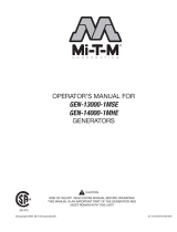
ENGINE SWITCH: (Fig. 15)
The engine switch is designed for easy operation with the
interlocking mechanism between the fuel valve and the
choke.
OUTPUT LAMP: (Fig. 16)
These lamps are turned on in the following conditions:
Output Lamp (Green) --- The lamp is turned on while
generating properly.
Oil Sensor Lamp --- (Fig. 17)
When the level of the engine oil falls below the prescribed
value, the alarm lamp lights up and the engine stops
automatically. When the engine stops due to oil shortage, it
can not be started anymore even by pulling the recoil starter
(just the alarm lamp ickers). In such a case, replenish
engine oil. See “Pre-Operation; Engine Oil” on page 21.
AC RECEPTACLES: (Fig. 18)
AC electric power is available through this receptacle. Use
a grounding type plug as shown on page 26, Table 1.
WARNING: DO NOT PUT FOREIGN OBJECTS
INTO THE PLUG RECEPTACLE.
CAUTION: DO NOT PLUG MORE THAN TWO
APPLIANCES INTO THE GENERATOR
AT A TIME.
DC TERMINAL: (Fig. 19)
DC electric power for battery charging is available.
- Red is positive (+) terminal.
- Black is negative (-) terminal.
ENGINE SWITCHES
CHOKE To start the engine, turn the
knob to the position. (Choke
valve is closed.)
RUN Keep the knob in this
position after the engine
starts. (The engine can be
started with the knob at the
position when the engine is
warm.
STOP To stop the engine, return
the knob to the position.
(The fuel cock is closed as
well.)
OUT
PUT
(Fig. 15)
(Fig. 16)
(Fig. 17)
(Fig. 19)
(Fig. 18)

Controls
Operator’s Manual 19
CONTROLS
DC CIRCUIT BREAKER: (Fig. 20)
DC circuit breaker shuts off electric current when the current
exceeds its limit.
Check for excessive current consumption or defects in the
appliance. After making sure everything is in order, push
the button to the “ON” position.
CAUTION: IF CIRCUIT BREAKER CONTINUES
TO TRIP, CHECK APPLIANCE FOR DEFECT.
IF GENERATOR IS MALFUNCTIONING,
SEE YOUR A UTHORIZED M I-T-M
SERVICE CENTER OR DEALER.
NEVER INTERFERE WITH THE OPERATION
OF THE CIRCUIT BREAKER KNOB OR
KEEP PUSHING IT IN THE “ON”
POSITION.
RECOIL STARTER: (Fig. 21)
Pull this handle to start the generator.
GROUND TERMINAL: (Fig. 22)
Terminal for grounding the generator.
FUEL TANK CAP: (Fig. 23)
The fuel tank cap is located under the cover. To open
the cover, lift up and towards the mufer end as shown
in the illustration. Remove the fuel tank cap by turning
counterclockwise.
SIDE COVER: (Fig. 24)
To access the following items for servicing, take the
applicable side cover out by removing the screw with a
screwdriver.
LH-Side Cover - Air cleaner, etc.
RH-Side Cover - Oil level gauge, Ignition Coil,
Spark Plug, etc.
(Fig. 20)
(Fig. 21)
(Fig. 22)
(Fig. 24)
(Fig. 23)
" "
" "
Button
Knob
IN (ON)
OUT (OFF)
Recoil Starter
Handle
Fuel Tank Cap
Fuel Filter Screen
Tank Cap Cover

20 Operator’s Manual
Preparing the Generator
(Fig. 1)
Ground Terminal
Grounding Rod
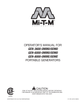
GROUNDING INSTRUCTIONS
This product must be grounded. If it should malfunction or
breakdown, grounding provides a path of least resistance for
electric current to reduce the risk of electric shock.
DANGER - IMPROPER CONNECTION OF THE
EQUIPMENT-GROUNDING CONDUCTOR CAN
RESULT IN A RISK OF ELECTROCUTION.
CHECK WITH A QUALIFIED ELECTRICIAN OR
SERVICE PERSON IF YOU ARE IN DOUBT AS
TO WHETHER THE UNIT IS PROPERLY
GROUNDED.
The ground terminal on the frame must always be used to
connect the generator to a suitable ground source. The ground
path should be made with #8 size wire. Connect the grounding
wire securely to the ground terminal. Connect the other end of
the wire securely to a suitable ground source. (Fig. 1)
The National Electric Code contains several practical ways in
which to establish a good ground source. Examples given below
illustrate a few of the ways in which a good ground source may
be established.
A metal underground water pipe in direct contact with the earth
for at least 10 feet can be used as a grounding source. If an pipe
is unavailable, an 8 foot length of pipe or rod may be used as the
ground source. The pipe should be 3/4 inch trade size or larger
and the outer surface must be noncorrosive. If a steel or iron rod
is used it should be at least 5/8 inch diameter and if a nonferrous
rod is used it should be at least 1/2 inch diameter and be listed
as material for grounding. Drive the rod or pipe to a depth of 8
feet. If a rock bottom is encountered less than 4 feet down, bury
the rod or pipe in a trench. All electrical tools and appliances
operated from this generator, must be properly grounded by use
of a third wire or be “Double Insulated”.
It is recommended to:
1. Use electrical devices with 3 prong power cords.
2. Use an extension cord with a 3 hole receptacle and a 3
prong plug at the opposite ends to ensure continuity of
the ground protection from the generator to appliance.
We strongly recommend that all applicable federal, state and
local regulations relating to grounding specications be checked
and followed.
LINE TRANSFER SWITCH
If this generator is used for standby service, it must have
a transfer switch between the utility power service and the
generator. The transfer switch not only prevents the utility
power form feeding into the generator, but is also prevents the
generator form feeding out into the utility company’s lines. This
is intended to protect the serviceman who may be working on
a damaged line.
THIS INSTALLATION MUST BE DONE BY A LICENSED
ELECTRICIAN AND ALL LOCAL CODES MUST BE
FOLLOWED.
/