Delta 132900-A Installation guide

Category
Sanitary ware
Type
Installation guide
MultiChoice
®
Valve Trim
Installation Instructions
Owners Manual
13/14
Series
Write purchased model number here.
Table of Contents:
Warranty .............................................................................. Page 2
MultiChoice
®
Rough-In Installation Instructions ................... Pages 3 - 5
13/14 Series Installation Instructions ................................... Pages 6 - 10
Maintenance ........................................................................ Page 11
Cartridge Summary References .......................................... Page 12
To order replacement parts, visit www.deltafaucet.com
1
You May Need
T
E
F
L
O
N
10/8/15
72264 Rev. F
CAUTION: This system/device must be set by the
installer to ensure safe, maximum temperature.
Any change in the setting may raise the discharge
temperature above the limit considered safe and
may lead to hot water burns.
NOTICE TO INSTALLER: CAUTION!–As the
installer of this valve, it is your responsibility
to properly INSTALL and ADJUST this valve
per the instructions given. This valve does
not automatically adjust for inlet temperature
changes, therefore, someone must make the
necessary Rotational Limit Stop or temperature
knob adjustments at the time of installation and
further adjustments may be necessary due to
seasonal water temperature change. YOU MUST
inform the owner/user of this requirement by
following the instructions. If you or the owner/
user are unsure how to properly make these
adjustments, please refer to pages 8 and 9, and if
still uncertain, call us at 1-800-345-DELTA.
After installation and adjustment, you must affix
your name, company name and the date you
adjusted the Rotational Limit Stop or temperature
knob to the caution label provided and apply or
attach the label to the back side of the closest
cabinet door and the warning label to the water
heater. Leave this Instruction Sheet for the
owner’s/user’s reference.
WARNING: This pressure balanced or
thermostatic bath valve is designed
to minimize the effects of outlet water
temperature changes due to inlet pressure
changes, commonly caused by dishwashers,
washing machines, toilets and the like. It may
not provide protection from hot water burns
when there is a failure of other temperature
controlling devices elsewhere in the
plumbing system, if the rotational limit stop
or temperature knob is not properly set or if
the hot water temperature is changed after the
settings are made or if the water inlet changes
due to seasonal changes.
WARNING: Do not install a shut-off device on
either outlet of this valve. When this type of
device shuts off the water flow, it can defeat
the ability of the valve to balance the hot and
cold water pressures.
72264
13/14 Series13/14 Series13/14 Series
2
© 2015 Masco Corporation of Indiana
Parts and Finish
All parts (other than electronic parts and batteries) and finishes of this Delta
®
faucet are warranted to the original
consumer purchaser to be free from defects in material and workmanship for as long as the original consumer
purchaser owns the home in which the faucet was first installed or, for commercial users, for 5 years from the
date of purchase.
Electronic Parts and Batteries (if applicable)
Electronic parts (other than batteries), if any, of this Delta
®
faucet are warranted to the original consumer
purchaser to be free from defects in material and workmanship for 5 years from the date of purchase or, for
commercial users, for one year from the date of purchase. No warranty is provided on batteries.
Delta Faucet Company will replace, FREE OF CHARGE, during the applicable warranty period, any part or
finish that proves defective in material and/or workmanship under normal installation, use and service. If repair
or replacement is not practical, Delta Faucet Company may elect to refund the purchase price in exchange for
the return of the product. These are your exclusive remedies.
Delta Faucet Company recommends using a professional plumber for all installation and repair. We also
recommend that you use only genuine Delta
®
replacement parts.
Delta Faucet Company shall not be liable for any damage to the faucet resulting from misuse, abuse, neglect
or improper or incorrectly performed installation, maintenance or repair, including failure to follow the applicable
care and cleaning instructions.
Replacement parts may be obtained by calling the applicable number below or by writing to:
In the United States and Mexico: In Canada:
Delta Faucet Company Masco Canada Limited, Plumbing Group
Product Service Technical Service Centre
55 E. 111th Street 350 South Edgeware Road
Indianapolis, IN 46280 St. Thomas, Ontario, Canada N5P 4L1
1-800-345-DELTA (3358) 1-800-345-DELTA (3358)
Proof of purchase (original sales receipt) from the original purchaser must be made available to Delta Faucet
Company for all warranty claims unless the purchaser has registered the product with Delta Faucet Company.
This warranty applies only to Delta
®
faucets manufactured after January 1, 1995 and installed in the United
States of America, Canada and Mexico.
DELTA FAUCET COMPANY SHALL NOT BE LIABLE FOR ANY SPECIAL, INCIDENTAL OR CONSEQUENTIAL
DAMAGES (INCLUDING LABOR CHARGES) FOR BREACH OF ANY EXPRESS OR IMPLIED WARRANTY
ON THE FAUCET. Some states/provinces do not allow the exclusion or limitation of special, incidental or
consequential damages, so these limitations and exclusions may not apply to you. This warranty gives you
special legal rights. You may also have other rights which vary from state/province to state/province.
This is Delta Faucet Company’s exclusive written warranty and the warranty is not transferable.
If you have any questions or concerns regarding our warranty, please view our Warranty FAQs at www.
deltafaucet.com, email us at [email protected] or call us at the applicable number above.
Limited Warranty on Delta
®
Faucets
SHUT OFF WATER SUPPLIES.
Consider the type and thickness of your
finished wall before placing your stringer
back plate. Install the body (1) so the
surface of the finished wall is flush with the
front of the plasterguard (2) ± 3/8". Note:
For models with stops (3), plasterguard
MultiChoice
®
Rough-In Installation
1
A.
B.
Distance (1) from the stringer (2) to the
front of the plasterguard is 2.8" (71 mm).
Distance (3) from the stringer (2) to the
front of the bonnet is 3.9" (99 mm).
must be flush or subflush 3/8" to
finished wall. Mount body using the two
stringer mounting holes (4) on the bracket.
Note: Remove cover (5) to access
mounting holes. Make sure the word
“UP” (6) is on top of the valve body when
installing.
If a thin wall is used, be sure to have the
plasterguard behind the wall, otherwise
the wall should always be flush with the
front of the plasterguard. See instruction
on the bag for thin wall mounting.
1
2
6
5
4
4
1
3
2
3
3
Connect valve body to water supplies using
the proper fittings for your valve body type
(copper tubing, iron pipe or Pex). Note: (1) is
the cold inlet port and (2) is the hot inlet
port. If either of the two outlet ports is to be
unused, seal the port with a pipe plug.
Remove bonnet (1). Warning: Avoid
soldering at high temperatures.
Be sure stops (2) are removed from the
w/stops version before soldering. (Do not
install stops before soldering.)
If you are making a back to back or
reverse installation (hot on right and
cold on left) install the valve body as
described, but the water supply lines will
be reversed. Note: (1) is the hot inlet
port and (2) is the cold inlet port.
Copper Tubing Iron Pipe
Pex
C.
1
2
1
2
1
2
MultiChoice
®
Rough-In Installation
D.
1
2
4
Connect top outlet (1) to shower pipe with
proper fittings. Connect bottom outlet (2) to tub
spout pipe with proper fittings. Pipe (3) between
valve body and tub spout must be a minimum of
1/2" (13 mm) copper pipe or 1/2" (13 mm) iron
pipe in a straight drop no less than 8" (203 mm)
but no more than 18" (457 mm) long with only
one iron pipe or copper 90 degree elbow to the
tub spout nipple. Do not use PEX tubing for
tub spout drop.
Prior to testing, remove cover (1) and bonnet
nut (2). Insert cartridge and tighten bonnet nut.
Turn cartridge stem counter clockwise until it will
no longer rotate. Plug both outlets with proper
fittings. Check for leaks. After testing, remove
cartridge, shower and/or tub spout plug and
flush system by slowly turning on water supply
to purge valve system of debris. After flushing,
reinstall cartridge (see page 6), bonnet nut
and cover. Install stops (3 & 4) in the models
with stops and set to full open. Note: Install
stops as follows: Thread nut (3) onto stem
(4) as shown. Then press stem and nut
assembly into body and tighten using a 3/8",
6 point, deep well socket. With a flat head
screwdriver, adjust stem clockwise to close
and counterclockwise to open.
E.
F.
MultiChoice
®
Rough-In Installation
1
2
3
PRESSURE TESTING & FLUSHING THE INSTALLATION
1
2
1
2
4
3
3
4
5
13 / 14 Series Installation
2
Cartridge Installation
C.
Turn off water supplies. Remove
cover (1) and bonnet nut (2) from the
body, if necessary. If this is not a thin
wall mounting, the entire plasterguard (3)
may be removed.
For back to back or reverse installations
(hot on right and cold on left) insert the
cartridge with the “hot side” on the right.
If you are not making a reverse or back
to back installation skip this step and
continue with step 1C.
Slide bonnet nut (1) over the cartridge
and thread onto the body. Hand tighten
securely.
B.
Rotate the cartridge (1) so the words
“hot side” (2) appear on the left. Insert
cartridge into valve body as shown. Make
sure the cartridge tubes and O-rings (3)
are properly seated in holes at the base of
the body. Ensure the keys on the body are
fully engaged with the slots in the body (4).
Back to back Installation
Normal Installation (changes not required)
Reverse
Installation
Cold
Hot
1
4
4
2
3
1
A.
1
2
3
6
13 / 14 Series Installation
3
Showerhead and Tub Spout Installation
FOR SHOWERHEAD INSTALLATION: Connect top
outlet (1) to shower arm (2) with proper fittings. To pre-
vent damage to finish on shower arm, insert wall end
of shower arm into shower flange (3) before screwing
arm into riser connection. Thread showerhead (4) onto
shower arm. Apply plumber tape to pipe threads on
both ends. Do not overtighten showerhead.
A.
-I- MODELS: To
combine the two
showers, insert the
top tab (1) on the
handshower into
the slot (2) of the
showerhead. Push the
handshower into the
showerhead until the
two parts snap together.
B.
-I- Models
3
2
1
4
2
1
4
3
Slip-On Installation
The copper tube (1) must be 1/2” nominal copper.
Important: If it is necessary to cut the copper tube,
the end must be chamfered free of burrs to prevent
cutting or nicking O-ring inside the spout. Slide spout
over copper tube flush with the finished tub or wall
surface. Tighten set screw (2), but do not overtighten.
1
FOR TUB SPOUT INSTALLATION:
Refer to the installation instructions supplied with your spout. Do not connect deck mount
spouts to in-wall valves. Do not use hand showers connected in lieu of a tub spout to a
tub/shower valve. Do not use PEX tubing for tub spout drop.
B-1
B-2
B-3
Iron Pipe Installation
Install threaded pipe nipple (1) to extend past
finished wall. Apply plumber tape to threads on
pipe nipple and screw on tub spout.
Copper Sweat Installation
Remove O-ring (1) from adapter (2). Solder adapter
to tube taking care to keep solder away from O-ring
groove. CAUTION: NO SOLDER PERMITTED ON
OUTSIDE DIAMETER OF ADAPTER ADJACENT
TO O-RING GROOVE. Cut off tube (3) and replace
O-ring on groove of brass adapter. Thread tub/spout
onto adapter, taking care not to damage O-ring, and
hand tighten until spout is firmly against finished
wall and all slack is taken up behind wall.
2
1
1
23
7
13 / 14 Series Installation
4
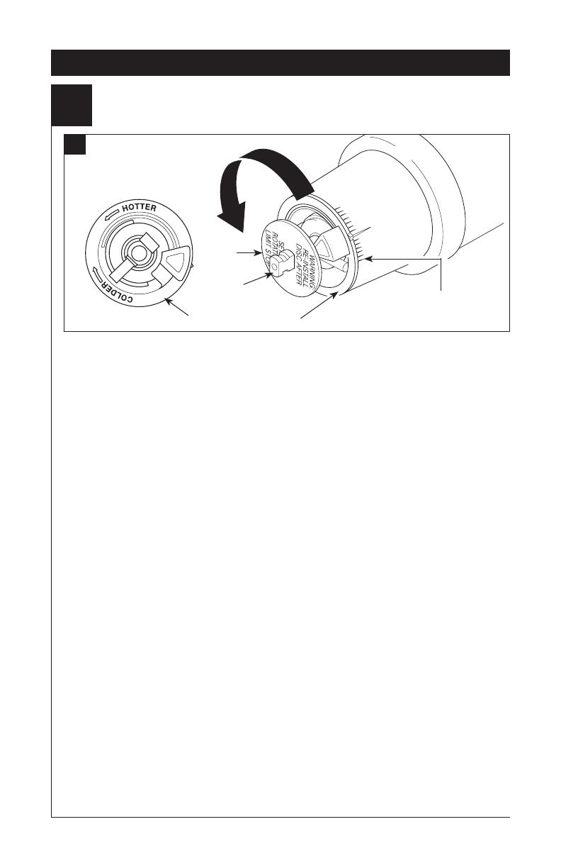
Adjusting the Rotational Limit Stop
IMPORTANT:
The Rotational Limit Stop is used to limit the
amount of hot water available such that, if set
properly, the user will not be scalded if the han-
dle accidentally is rotated all the way to “hot”
when a person is showering or filling a tub. The
first position allows the LEAST amount of hot
water to mix with the cold water in the system.
In the first position the water will be the coldest
possible when the handle is turned all the way
to hot. As you move the Rotational Limit Stop
counterclockwise, you progressively add more
and more hot water in the mix. The last position
to the left will result in the greatest amount of
hot water to the mix, and the greatest risk of
scald injury if someone accidentally turns the
valve handle all the way to the hot side while
showering or filling a tub.
WARNING: In some instances, setting the
Rotational Limit Stop in the hottest position
(full counterclockwise) could result in scald
injury. It is necessary to adjust the Rota-
tional Limit Stop so that the water coming
out of the valve will not scald the user when
the handle of the valve is rotated to the hot
side.
• According to the majority of industry stan-
dards, the maximum allowable temperature of
the water exiting the valve is 120°F (Your local
plumbing codes may require a water tempera-
ture less than 120°F).
The Rotational Limit Stop may need to be re-
adjusted seasonally if the inlet water tempera-
ture changes. For example, during the winter,
the cold water temperature is colder than it is
during the summer which could result in vary-
ing outlet temperatures. A water temperature
for a comfortable bath or shower is typically
between 90°F - 110°F.
• Run the water so that the cold water is as
cold as it will get and hot water is as hot as
it will get. Place the handle on the stem (see
page 10, step 5D) and rotate the handle
counterclockwise until the handle stops.
• Place a thermometer in a plastic tumbler
and hold in the water stream. If the water
temperature is above 120°F, the Rotational
Limit Stop must be repositioned clockwise to
decrease valve outlet water temperature to
be less than 120°F or to meet the require-
ments of your local plumbing codes.
To adjust the temperature of the water
coming out of the valve, pull the disc back to
a position where it is possible to remove the
Rotational Limit Stop and readjust the teeth
engagement position to the desired tem-
perature. Clockwise will decrease the outlet
temperature, counterclockwise will increase
the outlet temperature. Temperature change
per tooth (notch) could be 4° - 16°F based on
inlet water conditions. Repeat as necessary.
Push disc until fully seated.
WARNING: Failure to re-install Disc after
setting Rotational Limit Stop could result
in scald injury.
• MAKE SURE COLD WATER FLOWS
FROM THE VALVE FIRST. MAKE SURE
WATER FLOWING FROM THE VALVE
AT THE HOTTEST FLOW POSSIBLE
DOES NOT EXCEED 120°F OR THE
MAXIMUM ALLOWED BY YOUR LOCAL
PLUMBING CODE.
1st Position
Hotter
Rotational Limit Stop
Stem
Disc
A.
8
IMPORTANT:
The Rotational Limit Stop is used to limit the
amount of hot water available such that, if set
properly, a scald injury is less likely to occur if
the handle accidentally is rotated all the way
to “hot” when a person is showering or filling
a tub. The first position allows the LEAST
amount of hot water to mix with the cold water
in the system. In the first position the water
will be the coldest possible when the handle
is turned all the way to hot. As you move the
Rotational Limit Stop counterclockwise, you
progressively add more and more hot water in
the mix. The last position to the left will result
in the greatest amount of hot water to the mix,
and the greatest risk of scald injury if someone
accidentally turns the valve handle all the way
to the hot side while showering or filling a tub.
WARNING: In some instances, setting the
Rotational Limit Stop in the hottest position
(full counterclockwise) could result in
scald injury. It is necessary to adjust the
Rotational Limit Stop so that the water
coming out of the valve will not scald the
user when the handle of the valve is rotated
to the hot side.
• According to the majority of industry
standards, the maximum allowable temperature
of the water exiting the valve is 120°F (Your
local plumbing codes may require a water
temperature less than 120°F).
The Rotational Limit Stop may need to
be re-adjusted seasonally if the inlet water
temperature changes. For example, during the
winter, the cold water temperature is colder
than it is during the summer which could
result in varying outlet temperatures. A water
temperature for a comfortable bath or shower is
typically between 90°F - 110°F.
• Run the water so that the cold water is as cold
as it will get and hot water is as hot as it will
get. Place the handle on the stem and rotate
the handle coun- terclockwise until the handle
stops.
• Place a thermometer in a plastic tumbler
and hold in the water stream. If the water
temperature is above 120°F, the Rotational
Limit Stop must be repositioned clockwise to
decrease valve outlet water temperature to
be
less than 120°F or to meet the
requirements of
your local plumbing codes.
To adjust the temperature of the water coming
out of the valve, pull the white Rotational
Limit Stop (1) outward and rotate. Clockwise
rotation will decrease the outlet temperature,
counterclockwise rotation will increase the
outlet temperature. Temperature change per
tooth (notch) could be 4° - 16°F based on inlet
water conditions. Repeat as necessary. When
finished, make sure that the Rotational Limit
Stop is fully retracted into the seated position.
WARNING: Do not take the Rotational Limit
Stop apart.
• MAKE SURE COLD WATER FLOWS
FROM THE VALVE FIRST. MAKE SURE
WATER FLOWING FROM THE VALVE AT
THE HOTTEST FLOW POSSIBLE DOES
NOT EXCEED 120°F OR THE MAXIMUM
ALLOWED BY YOUR LOCAL PLUMBING
CODE.
13 / 14 Series Installation
Hotter
Cooler
1
1
B.
9
13 / 14 Series Installation
5
Trim Installation
C.
D.
A.
B.
Slide O-ring (1) over cartridge and the
bonnet nut (2). The O-ring, which acts as
a spacer to steady the sleeve, should rest
behind the bonnet nut.
If your model requires a spacer (1), insert
it into the sleeve (2) and push it to the
front. Slide the sleeve over the cartridge,
body and O-ring.
Secure the escutcheon (1) and backplate
(2) (if your model has one) to the bracket
(3) using the 2 screws provided (4). Do not
overtighten escutcheon screws.
Using an Allen wrench to secure the set
screw, install the handle onto the stem.
1
2
1
2
1
1
2
3
4
10
Faucet leaks from tub spout/showerhead:
SHUT OFF WATER SUPPLIES.
Replace seats and springs–Repair
Kit RP4993. Check condition of lower O-rings and
replace if necessary RP14414. See Helpful Hints
1, 2, & 3.
If leak persists:
SHUT OFF WATER SUPPLIES.
Replace valve cartridge RP46074.
See Helpful Hints 1, 2, 3 & 5.
Unable to maintain constant water temperature:
Replace valve cartridge RP46074 or follow
instructions in Helpful Hints 1, 2, 4 & 5.
Helpful Hints:
1. Before removing valve cartridge assembly for any
maintenance, be sure to note the position of the
rotational limit stop on the cap. The valve cartridge
assembly must always be put back in the same
position. BE SAFE! After you have finished the
installation, turn on valve to make sure COLD
WATER FLOWS FIRST.
2. To remove valve cartridge from body, shut off
water supplies and remove handle and bonnet
nut. Do not pry the valve cartridge out of the body
with a screwdriver. Place handle on stem and rotate
counterclockwise approximately 1/4 turn after the stop
has been contacted. Lift valve cartridge out of body.
3. To remove seats and springs, remove valve
cartridge. Separate cap assembly from the
housing assembly by rotating the cap assembly
counterclockwise 90
o
(degrees). Separate cap
and housing assemblies. Remove seats and
springs and replace. Place the largest diameter
of the spring into the seat pocket first and then
press the tapered end of the seal over the spring.
Reassemble valve cartridge and replace in body
following instructions given in 1 above.
4. If the water in your area has lime, rust, sand or
other contaminants in it, your pressure balance
valve will require periodic inspection. The
frequency of the inspection will depend on the
amount of contaminants in the water. To inspect
valve cartridge remove it and follow the steps
in note 1 above. Turn the valve to the full mix
position and shake the cartridge vigorously. If
there is a rattling sound, the unit is functional and
can be reinstalled following instructions given in
note 1 above. If there is no rattle, replace valve
cartridge RP46074.
5. Push disc until fully seated. See pages 8 and 9
for more details.
To order replacement parts, visit
www.deltafaucet.com or call
1-800-345-DELTA (3358)
13/14 Series Maintenance
Cleaning and Care
Care should be given to the cleaning of this prod-
uct. Although its finish is extremely durable, it can
be damaged by harsh abrasives or polish. To clean,
simply wipe gently with a damp cloth and blot dry
with a soft towel.
Warning: Scrubbing Bubbles
®
Bathroom Cleaner
and Lysol
®
Basin Tub and Tile Cleaner must not be
used on the clear knob handles and levers. Use of
these cleaners can result in cracked or severely
damaged handles. If overspray gets onto the
handles, immediately wipe them dry with a soft
cotton cloth
11
12
Cartridge Summary Reference Sheet
Monitor
®
Series 1300/1400
Cartridge shipped before March 2006.
Cartridge shipped in July 2006 and after
(prior to MultiChoice
®
transition).
Shorter lower
housing
Blue or
off-white
White
Shorter lower
housing
White
Blue
Order RP19804 to replace cartridge. Order RP19804 to replace cartridge.
MultiChoice
®
13/14
Cartridge shipped from March 2006 to August 2014. Cartridge shipped in August 2014 and after.
Longer lower
housing
Grey
Off-white
Longer lower
housing
Grey
Off-white
Order RP46074 to replace cartridge. Order RP46074 to replace cartridge.
NOTE: A running change for MultiChoice
®
13/14 valves began August 2014, and
features a new Rotational Limit Stop.
MultiChoice
®
13/14 (Ceramic)
Cartridge shipping in select models (-CER).
Grey
White
Order RP74236 to replace cartridge.
INTERROMPEZ L’ALIMENTATION EN EAU.
Déterminez le type de la paroi et son
épaisseur totale avant de placer la plaque
arrière. Installez le corps (1) de sorte que
la surface finie de la paroi soit à égalité
avec l’avant du protecteur (2) ± 3/8 po.
Note : Pour avec des modèles d’arrêts
(3), la garde de plâtre doit être l’éclat
affleurant ou secondaire 3/8 po au
Installation de la plomberie brute MultiChoice
®
1
mur fini. Installez le corps utilisez les
deux trous (4) de la fixation qui donnent
sur l’entretoise. Note : Enlevez le cou-
vercle (5) pour découvrir les trous de
montage. Au moment de l’installation,
assurez-vous que le mot « UP » (6) sur
le dessus du corps de robinet se trouve
en haut.
A.
B.
1
2
6
5
4
4
1
3
2
3
Distance (1) from the stringer (2) to the
front of the plasterguard is 2.8" (71 mm).
Distance (3) from the stringer (2) to the
front of the bonnet is 3.9" (99 mm).
If a thin wall is used, be sure to have the
plasterguard behind the wall, otherwise
the wall should always be flush with the
front of the plasterguard. See instruction
on the bag for thin wall mounting.
3
Notes / Notas / Notes
13
Delta Faucet Company
Product Service
55 E. 111th Street
Indianapolis, IN 46280
  • Page 1 1
  • Page 2 2
  • Page 3 3
  • Page 4 4
  • Page 5 5
  • Page 6 6
  • Page 7 7
  • Page 8 8
  • Page 9 9
  • Page 10 10
  • Page 11 11
  • Page 12 12
  • Page 13 13
  • Page 14 14
  • Page 15 15
  • Page 16 16
  • Page 17 17
  • Page 18 18
  • Page 19 19
  • Page 20 20
  • Page 21 21
  • Page 22 22
  • Page 23 23
  • Page 24 24
  • Page 25 25
  • Page 26 26
  • Page 27 27
  • Page 28 28
  • Page 29 29
  • Page 30 30
  • Page 31 31
  • Page 32 32
  • Page 33 33
  • Page 34 34
  • Page 35 35
  • Page 36 36
  • Page 37 37
  • Page 38 38

Delta 132900-A Installation guide

Category
Sanitary ware
Type
Installation guide

Ask a question and I''ll find the answer in the document

Finding information in a document is now easier with AI