Frigidaire FMV152KQA Installation guide
- Category
- Microwaves
- Type
- Installation guide

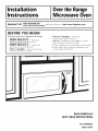
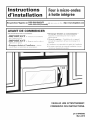
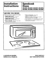
Installation
Instructions
Overthe Range
Microwave Oven
I
Questions? Carl 1-800-944-9044(us)
1-800-265-8352(Canada)
or Visit our Website at: http://www.frigidaire.com
I
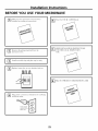
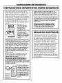
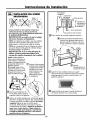
BEFORE YOU BEGIN
Read these instructions completely and carefully.
• IMPORTANT - Savethese
instructions for local inspector's use.
• IMPORTANT - Observoall
governing codes and ordinances.
• Note to Installer - Be sure to leave these
instructions with the Consumer.
• Note to Consumer - Keep these
instructions for future reference.
• Skill level - Installation of this appliance requires
basic mechanical and electrical skills.
• Proper installation is the responsibility of the installer.
• Product failure due to improper installation is not
covered under the Warranty.
/
/
READ CAREFU LLY.
KEEP THESE INSTRUCTIONS.
pin 316495063
March 2010

Installation Instructions
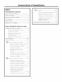
CONTENTS
General information
Important Safety Instructions .................................. 3
Electrical Requirements .......................................... 3
Damage - Shipment/Installation .............................. 4
Parts Included .......................................................... 4
Tools You Will Need ................................................ 5
Mounting Space ...................................................... 5
Step-by-step installation guide
Placement of The Mounting Plate ...................... 6-8
Removing the Mounting Plate ...................... 6
Finding the Wall Studs .................................. 6
Determining Wall Plate Location .................. 7
Aligning the Wall Plate ................................ 8
Installation Types ............................................... 9-22
Hood Exhaust .................................................. 10-11
_ Outside Top ............................
Exhaust 12-15
Attach Mounting Plate to Wall ............ 12
Preparation of Top Cabinet ................ 13
Adapting Microwave Blower for
Outside top Exhaust .................. 13-14
Checking for Proper Damper
Operation ............................................ 14
Mount the Microwave Oven .......... 14-15
Adjust the Exhaust Adaptor ................ 15
Connecting Ductwork .......................... 15
]Outside Back Exhaust 16-19
Preparing Rear Wall for
Outside Back Exhaust .......................... 16
Remove Blower Plate .............................. 16
Attach Mounting Plate to Wall ............ 17
Preparation of Top Cabinet ................ 17
Adapting Microwave Blower
for Outside Back Exhaust ................ 17-18
Mount the Microwave Oven ................ 19
[] Recirculating ........................................
20 _ 2 2
Attach Mounting Plate to Wall ............ 20
Preparation of Top Cabinet ................ 20
Check Blower Plate ............................ 21
Mount the Microwave Oven .......... 21-22
Installing or Change the
Charcoal Filter .................................... 22
Before You Use Your Microwave .......................... 23
2

Installation Instructions
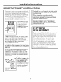
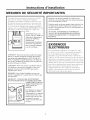
IMPORTANT SAFETY INSTRUCTIONS
This product requires a three-prong grounded outlet.
The installer" must perform a ground continuity check
on the power" outlet box before beginning the
installation to insure that the outlet box is properly
grounded. If not properly grounded, or" if the outlet
box does not meet electrical requirements noted
(under ELECTRICAL REQUIREMENTS), a qualified
electrician should be employed to correct any
deficiencies.
CAUTION: For personal
safety, remove house fuse
or open circuit breaker
before beginning
installation to avoid severe
or fatal shock injury.
CAUTION: For personal safety, the mounting surface
must be capable of supporting the cabinet load, in
addition to the added weight of this 63-85 pound
(28.5-38.5 kg) product, plus additional oven loads of
up to 50 pounds (22.7 kg) or a total weight of
113-135 pounds (51.3-61.2 kg).
CAUTION: For personal safety, this product cannot
be installed in cabinet arrangements such as an island or
a peninsula. It must be mounted to BOTH a top cabinet
AND a wall.
NOTE: For easier installation and personal safety, it is
recommended that two people install this product.
IMPORTANT - PLEASE READ CAREFULLY. FOR
PERSONAL SAFETY, THIS APPLIANCE MUST BE
PROPERLY GROUNDED TO AVOID SEVERE OR
FATAL SHOCK.
Ensureproper
groundexists
beforeuse
The power cord of this
appliance is equipped with a
three-prong (grounding)
plug which mates with a
standard three-prong
(grounding) wall receptacle
to minimize the possibility
of electric shock hazard
from this appliance.
You should have the wall receptacle and circuit checked
by a qualified electrician to make sure the receptacle is
properly grounded.
Where a standard two-prong wall receptacle is
encountered, it is very important to have it replaced
with a properly grounded three-prong wall receptacle,
installed by a qualified electrician.
DO NOT, UNDER ANY CIRCUMSTANCES, CUT,
DEFORM OR REMOVE ANY OF THE PRONGS
FROM THE POWER CORD. DO NOT USE WITH
AN EXTENSION CORD.
ELECTRICAL
REQUIREMENTS
Product rating is 120 volts AC, 60 Hertz, 15 amps and
1.6 kilowatts. This product must be connected to a
supply circuit of the proper voltage and frequency.
Wire size must conform to the requirements of the
National Electrical Code or the prevailing local
code for this kilowatt rating. The power supply
cord and plug should be brought to a separate
15- to 20- ampere branch circuit single grounded
outlet. The outlet box should be located in the
cabinet above the microwave oven. The outlet box
and supply circtfit should be installed by a qualified
electrician and conform to the National Electrical
Code or the prevailing local code.
3

Installation Instructions
DAMAGE--SHIPMENT/
INSTALLATION
• If the unit is damaged in shipment, return the
unit to the store in which it was bought for repair
or replacement.
• If the unit is damaged by the customer, repair or
replacement is the responsibility of the customer.
• If the unit is damaged by the installer (if other
than the customer), repair or replacement must
be made by arrangement between customer
and installer
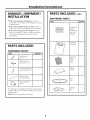
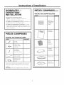
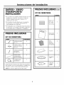
PARTS INCLUDED
HARDWARE PACKET
PART
/
+
!
Wood Screws
(1/4" X 2")
ToggleBolts(and
wingnuts)(3/16"x3")
Sel?AligningMachine
Screws(1/4"-28x 31/4'')
NylonGrommet
(formetalcabinets)
PowerCordStrap
(plastic)
QUANTITY
2
You will find the installation hardware contained in
a packet with the unit. Check to make sure you have
all these parts.
NOTE: Some extra parts are included.
PARTS INCLUDED (CONT.)
ADDITIONAL PARTS
PART QUANTITY
i_!i_i!_!iiii_ii!i!i!ii!i_i!_ii!i!iii_iiii_i!i!i!i!i!_!__ii_i!___i!_i!!i!_!!!!!iiiiiiiii!!!ii!!!i_i_!_!i!i_i_i!i_i!ii!i!iii!iiiii!i!!i!!i!!i!i!i!iiiiiii!ii!i!i!iiii!iii_i'
i
CombinedTop
Cabinet
Templateand
Rear Wall
Template
Installation
Instructions
Separately
Packed
Grease
Filters
Exhaust
adaptor
Glass
Tray
Turntable
Ring
4

Installation Instructions
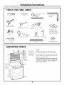
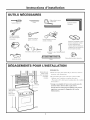
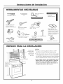
TOOLS YOU WILL NEED
# 1Phillipsscrewdriver
Tinsnips(forcutting
damper,if required)
Gloves
Safetygoggles
Pencil
Ruleror tapemeasureand
t edge
Scissors
(tocuttemplate,if necessary)
din===--
Saw(saber,holeor keyhole)
Electricdrill with 3/16",1/2"and%"
drill bits
0
Studfinder or
Hammer(optional)
Level
Carpentersquare
(optional)
Fillerblocksor scrap
woodpieces,if needed
fortop cabinetspacing
(usedonrecessedbottom
cabinetinstallationsonly)
Ductandmaskingtape
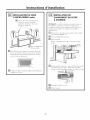
MOUNTING SPACE
--3
66" (167,6cm)
or Morefrom
the Floorto the
Topof the
Microwave
BottomEdgeof
CabinetNeedsto
be30" (76,2cm)
or Morefrom the
CookingSurface
Backsplash
NOTES:
• The space between the cabinets must be
30" (76.2 cm)wide and free of obstructions.
• If you are going to vent your microwave oven
to the outside, see Hood Exhaust Section for
exhaust duct preparation.
• When installing the microwave oven beneath
smooth, flat cabinets, be careful to follow the
instructions on the top cabinet template for
power cord clearance.
5

Installation Instructions
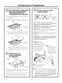
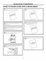
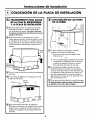
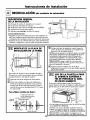
PLACEMENT OF THE MOUNTING PLATE
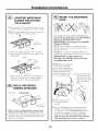
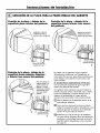
I-_ REMOVING THE MICROWAVE
OVEN FROM THE CARTON/
REMOVING THE MOUNTING
PLATE
[]Remove the installation instructions, filters, glass
tray and the small hardware bag. Do not remove
the Styrofoam protecting the front of the oven.
[] Fold back all 4 carton flaps fully against carton
sides. Then carefully roll the oven and carton over
onto the top side The oven should be resting in
the Styrofoam.
Styrofoam_
[]Pull the carton up and off the oven
Cut the middle of the outer protective plastic bag to
remove the mounting plate
Mounting
Screws-_ Plate
i
f
u
[]Remove the screws from the mounting plate.
This plate will be used as the rear wall template
and for mounting. Reinstall the screws into the
holes where they were removed.
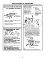
I-_ FINDING THE WALL STUDS
i waRm
i Studs
[]Find the studs, using one of the following
methods:
A. Stud finder - a magnetic device which
locates nails.
OR
B. Use a hammer to tap lightly across the
mounting surface to find a solid sound.
This will indicate a stud location
[] After locating the stud(s), find the center by
probing the wall with a small nail to find the edges
of the stud. Then place a mark halfway between
the edges. The center of any adjacent studs should
be 16" (40.6 cm) or 24" (61 cm) from this mark.
[]Draw a line down the center of the studs.
THE MICROWAVE MUST BE CONNECTED TO
AT LEAST ONE WALL STUD.
6

Installation Instructions
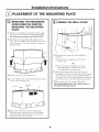
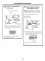
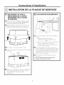
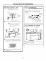
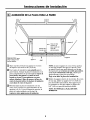
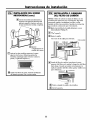
DETERMINING WALL PLATE LOCATION UNDER YOUR CABINET
Plate positionmbeneath flat bottom
cabinet
Plate positionmbeneath framed recessed
cabinet bottom
MountingPlateTabs
Touchingthe CabinetBottom
At least30" (76.2cm),
upto 36" (9!.4 cm)
MountingPlateTabs
.Touchingthe BackFrame
i
I
I ii 30" (76,2 cm)
to Cooktop
Plate position_beneath recessed bottom
cabinet with front overhang
Mounting Plate with
Tabs Below Cabinet
Bottom the Same
Distance as the Front
Overhang Depth
30" (76,2 cm)
to Cooktop
!
Your cabinets may have decorative trim that
interferes with the microwave installation. Remove
the decorative trim to install the microwave properly
and to make it level.
THE MICROWAVE MUST BE LEVEL.
Use a level to make sure the cabinet bottom is level.
If the cabinets have a front overhang only, with no
back or side frame, install the mounting plate down
the same distance as the front overhang depth. This
will
[]
%
%
keep the microwave level.
Measure the inside depth of the front overhang.
Draw a horizontal line on the back wall an equal
distance below the cabinet bottom as the inside
depth of the front overhang.
For this type of installation with front overhang only,
align the mounting tabs with this horizontal line, not
touching the cabinet bottom as described in Step D.
7

Installation Instructions
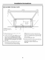
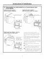
ALIGNING THE WALL PLATE
CAUTION: Wear gloves
to avoid cutting fingers on
sharp edges.
j_,,_ Draw a Vertical
i Line on Wall _I
I from Center of ,:1
Centerline i Top Cabinet t!t
Notches i I_I
I
-_? o o ? o o cF--o---_o c _ o o Or---o-_o o o_
I ,
Hole C Area E
I
I
\ HoleD
[]Draw a vertical line on the wall at the center of the
30" (76.2 cm) wide space.
[]Use the mounting plate as the template for the rear
wall. Place the mounting plate on the wall, making
sure that the tabs are touching the bottom of the
cabinet or the level line drawn in Step C for cabinets
with front overhang. Line up the notch and centerline
on the bottom of the mounting plate to the centerline
on the wall.
[]While holding the mounting plate with one hand,
draw circles on the wall at holes A, B, C and D
(see illustration above/actual plate marked with
arrows). Four holes must be used for mounting.
NOTE: If neither C nor D is in a stud, find a stud
somewhere in area E and draw a fifth circle to line up
with the stud. It is important to use at least one wood
screw mounted firmly in a stud to support the weight
of the microwave.
Set the mounting plate aside.
Drill holes on the circles. If there is a stud, drill a sad'
hole for wood screws. For holes that don't line up with
a stud, drill a 5/_,, hole for toggle bolts.
NOTE: DO NOT MOUNT THE PLATE AT
THIS TIME.
8

Installation Instructions
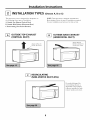
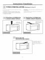
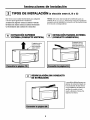
INSTALLATION TYPES
This microwave oven is designed for adaptation to
the following three types of ventilation:
A. Outside Top Exhaust (Vertical Duct)
B. Outside Back Exhaust (Horizontal Duct)
C. Recirculating (Non-Vented Ductless)
(Choose A, B or C)
NOTE: This microwave is shipped assembled for
Recirculating. Select the type of ventilation required
for your installation and proceed to that section.
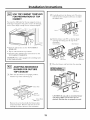
-_ OUTSIDE TOP EXHAUST
(VERTICAL DUCT)
OUTSIDE BACK EXHAUST
(HORIZONTAL DUCT)
Adaptorin Placefor
OutsideTopExhaust
AdaptorMust Be
Movedto the Backfor
OutsideBackExhaust
[_ RECIRCULATING
(NON-VENTED DUCTLESS)
On models shipped for
recirculating exhaust, a
disposable charcoal filter
is factory installed to help
remove smoke and odors.
9

Installation Instructions
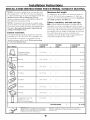
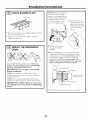
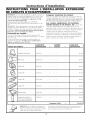
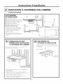
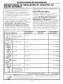
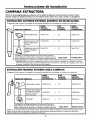
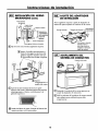
INSTALLATION INSTRUCTIONS FOR EXTERNAL EXHAUST DUCTING
NOTE: If you need to install ducts, note that the total
duct length of 31/4" x 10" (8.2 x 25.4 cm) rectangular or
5" (10.5 cm) diameter/ 6" (15.2 cm) diameter round duct
should not exceed 120 equivalent feet (36.5 m).
Outside ventilation requires a EXTERNAL EXHAUST
DUCT.Read the following carefully.
NOTE: It is important that venting be installed using
the most direct route and with as few elbows as possible.
This ensures clear venting of exhaust and helps prevent
blockages. Also, make sure dampers swing freely and
nothing is blocking the ducts.
Exhaust connection:
The exhaust adaptor has been designed to mate with
a standard 31/4'' x 10" (8.2 x 25.4 cm) rectangular duct.
If a round duct is required, a rectangular-to-round
transition adaptor must be used. Do not use less than
a 6" (15.2 cm) diameter duct.
Maximum duct length:
For satisfactory air movement, the total duct length of
31/4'' x 10" (8.2 x 25.4 cm) rectangular or 5" (10.5 cm)
diameter/6 "(15.2 cm) diameter round duct should not
exceedl20 equivalent feet (36.5 m).
Elbows, transitions, wall and roof caps,
etc., present additional resistance to airflow and are
equivalent to a section of straight duct which is longer
than their actual physical size. When calculating the total
duct length, add the equivalent lengths of all transitions
and adaptors phrs the length of all straight duct sections.
The chart below shows you how to calculate total
equivalent ductwork length using the approximate feet
of equivalent length of some typical ducts.
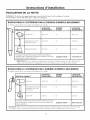
DUCT PIECES
&
J
@
0
J
Rectangular-to-Round
TransitionAdaptor*
Wall Cap
90° Elbow
45° Elbow
90° Elbow
45° Elbow
RoofCap
StraightDuct6" (15,2cm)
Roundor31/4``x 10"
(8,2x25,4cm)Rectangular
EQUIVALENT
LENGTH
5 Ft,(1,5m)
40Ft,(12,2m)
10Ft,(3m)
5 Ft,(1,5m)
25Ft,(7,6m)
5 Ft,(1,5m)
24Ft,(7,3m)
1 Ft,(0,3m)
NUMBER
x USED
x ()
x ()
x ()
x ()
x ()
x ()
x ()
x ()
Total Ductwork
EQUIVALENT
LENGTH
Ft,orm
Ft,orm
Ft,orm
Ft,orm
Ft,orm
Ft,orm
Ft,orm
Ft,orm
Ft. or m
* IMPORTANT: If a rectangular to round transition
adaptor is used, the bottom corners of the damper
will have to be cut to fit, using the tin snips, in order
to allow free movement of the damper.
Equivalent lengths of duct pieces are based on actual tests
and reflect requirements ti)r good venting pertbrmance with
any vent hood.
10

Installation Instructions
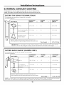
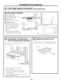
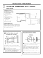
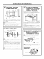
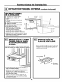
EXTERNAL EXHAUST DUCTING
NOTE: Read these next two pages only if you plan to vent your exhaust to the
outside. If you plan to recirculate the air back into the room, proceed to page 20.
OUTSIDE TOP EXHAUST (EXAMPLE ONLY)
The following chart describes an example of one possible
ductwork installation.
DUCT PIECES
Roof Cap
EQUIVALENT NUMBER EQUIVALENT
LENGTH x USED = LENGTH
24Ft,(7,3m) x (1) 24Ft,(7,3m)
12Ft,(3,6m)StraightDuct 12 Ft,(3,6m) x (1) = 12 Ft,(3,6m)
(6'715,2cmRound)
Rectangular-to-Round 5 Ft,(1,5m) x (1) = 5 Ft,(1,5m)
TransitionAdaptor*
Equivalentlengthsofductpiecesarebasedonactualtestsand
reflectrequirementsfor goodventingperformancewith anyvent hood,
Total Length = 41 Ft. (12.5 m)
* IMPORTANT: If a rectangular-to-round transition adaptor is used, the bottom corners of the damper
will have to be cut to fit, using the tin snips, ira order to allow fi'ee movement of the damper:
OUTSIDE BACK EXHAUST (EXAMPLE ONLY)
The following chart describes an example of one possible
ductwork installation.
EQUIVALENT NUMBER EQUIVALENT
LENGTH* USED = LENGTHDUCT PIECES x
":_::[_ Cap (12,2m) x
Wall 40Ft,
3Ft,StraightDuct 3Ft,(0,9m) x
(31/g'x 10'78,2x25,4cm
Rectangular)
(_ 90° Elbow 10Ft,(3m) x
(1) 40Ft,(12,2m)
(1) = 3Ft,(0,9m)
(2) = 20Ft,(3m)
Equivalentlengthsof ductpiecesarebasedonactualtests and
reflectrequirementsfor goodventingperformancewith anyventhood,
Total Length = 63 Ft. (19.2 m)
NOTE: For- back exhaust, care should be taken to align exhaust with space between studs, or"wall should be prepared
at the time it is constructed by leaving enough space between the wall studs to accommodate exhaust.
11

Installation Instructions
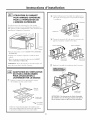
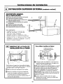
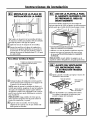
OUTSIDE TOP EXHAUST (Vertical Duct)
INSTALLATION OVERVIEW
A|. Attach Mounting Plate to Wall
A2. Prepare Top Cabinet
A3. Adapting Microwave Blower for
Outside Top Exhaust
A4. Check Damper Operation
A5. Mount Microwave Oven
A6. Adjust Exhaust Adaptor
A7. Connect Ductwork
IMPORTANT NOTES:
• Make sure the screws for the
blower motor and blower plate
are securely tightened when
they are reinstalled. This will
help to prevent excessive
vibration.
• Make sure the motor wiring has
been properly routed and secured,
and that the wires are not pinched.
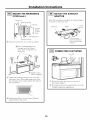
ATTACH THE MOUNTING
PLATE TO THE WALL
Attach the plate to the wall using toggle bolts.
At least one wood screw must be used to attach
the plate to a wall stud.
[]Remove the from the bolts.
toggle
wings
[]Insert the bolts into the mounting
plate
through the holes designated to go into drywall
and reattach the toggle wings to 3/4" (19 mm) onto
each bolt.
To use toggle bolts:
Mounting
Plate,
Spacing for Toggles
More Than Wall
-_l_i_--Thickness
I
iToggle Wings
Bolt End
]Place the mounting plate against the wall and
insert the toggle wings into the holes in the wall
to mount the plate.
NOTE: Before tightening toggle bolts and wood
screw, make sure the tabs on the mounting plate
touch the bottom of the cabinet when pushed
flush against the wall and that the plate is properly
centered under the cabinet.
CAUTION: Be careful to avoid pinching fingers
between the back of the mounting plate and the wall.
]Tighten all bolts. Pull the plate away fl'om the wall
to help tighten the bolts.
12

Installation Instructions
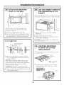
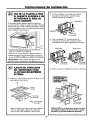
I-_ USE TOP CABINET TEMPLATE
FOR PREPARATION OF TOP
CABINET
You need to drill holes for the top support screws, a
hole large enough for the power cord to fit through,
and a cutout large enough for the exhaust adaptor.
• Read the instructions on the TOP CABINET
TEMPLATE.
• Tape it underneath the top cabinet.
• Drill the holes, following the instructions on the
TOP CABINET TEMPLATE.
CAUTION: Wear safety goggles when drilling holes
in the cabinet bottom.
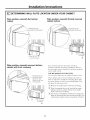
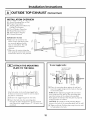
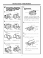
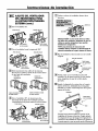
ADAPTING MICROWAVE
BLOWER FOR OUTSIDE
TOP EXHAUST
[] Place the microwave in its upright position,
with the top of the unit facing up.
?
I
I
_ BI0wer Plate
<l__---------._,_--__f] 1 Back0r
Micr0wave
,ow r o,or
Screw
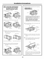
Remove the screw that holds the blower plate
to the microwave. Remove and save the screw
holding the blower motor to the microwave.
Careflflly pull out the blower unit. The wires
will extend far enough to allow you to adjust
the blower unit.
jEnd B
EndA _P'_ _
Microwave
Roll the blower unit 90 ° so that fan blade
openings are facing out the top of the
microwave.
Before Rotation After Rotation
Microwave
Backof
Microwave
[]Place the blower unit back into the opening.
Backof
Microwave
CAUTION: Do not pull or stretch the blower
unit wiring. Make sure the wires are not
pinched, and that they are properly secured.
13

Installation Instructions
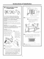
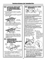
ADAPTING MICROWAVE
BLOWER FOR OUTSIDE
TOP EXHAUST
Secure blower unit to microwave with the screw
removed in Step 1. Make sure the screw is tight.
Replace blower plate with the screw removed in
Step 1. Make sure the screw is tight.
T
I
Back of
Micr0wave
[]
Attach the exhaust adaptor to the top of the
blower plate by sliding it into the guides of the
blower plate.
Adaptor
k0cking lab
Push in securely until it is in the locking tabs.
Take care to assure that the damper hinge is
installed so that the damper swings freely.
I-_ CHECK FOR PROPER
DAMPER OPERATION
Blower Plate Exhaust Adaptor
X ,,_,,,___----Damper
• Make sure tape securing damper is removed and
damper pivots easily before mounting microwave.
• You will need to make adjustments to assure proper
alignment with your house exhaust duct after the
microwave is installed.
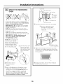
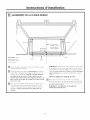
MOUNT THE MICROWAVE
OVEN
FOR EASIER INSTALLATION AND PERSONAL
SAFETY, WE RECOMMEND THAT TWO PEOPLE
INSTALL THIS MICROWAVE OVEN.
IMPORTANT: Do not grip or use handle
during installation.
NOTE: If your cabinet is metal, use the nylon
grommet around the power cord hole to prevent
cutting of the cord.
NOTE: We recommend using filler blocks if the
cabinet front hangs below the cabinet bottom shelf.
IMPORTANT: If filler blocks are
not used, case damage may occur from
overtightening screws.
NOTE: When mounting the
microwave oven, thread
power cord through hole in
bottom of top cabinet. Keep
it tight throughout Steps
1-3. Do not pinch cord or
lift oven by pulling cord.
[]Rotate fl'ont of
oven
up against cabinet
bottom.
%
[]Lift tilt it
microwave,
forward, and hook
slots at back bottom
edge onto four lower
tabs of mounting
plate.
Insert a self-aligning screw through top center
cabinet hole. Temporarily secure the oven by
turning the screw at least two full turns after the
threads have engaged. (It will be completely
tightened later.) Be sure to keep power cord
tight. Be careful not to pinch the cord, especially
when mounting flush to bottom of cabinet.
14

Installation Instructions
MOUNT THE MICROWAVE
OVEN (cont.)
Cabinet Front
..._._/_ Cabinet Bottom Shelf
/ Filler Block
/_,-- ;:::___
/ _F_[_/_ TEq uivalent
/ | : :bPitnhet
_:__!tI II:' _L Recess
J"\l !U _-_ Self-Aligning Screw
Microwave OvenTop
I_ Attach the microwave oven to the top cabinet.
[] Insert 2 self-aligning screws
through outer top cabinet
holes. Turn two flfll turns on
each screw.
[]Tighten center
screw completely.
[] Tighten the outer two screws to the top of the
microwave oven. (While tightening screws, hold
the microwave oven in place against the wall and
the top cabinet.)
[] Install grease filters. See the Owner's Manual
packed with the microwave.
ADJUST THE EXHAUST
ADAPTOR
Open the top cabinet and adjust the exhaust adaptor
to connect to the house duct.
Backof
BlowerPlate Damper Microwave
Side-to-SideAdjustment,
Slidethe ExhaustAdaptor
asNeeded
I-_ CONNECTING DUCTWORK
HouseDuct
]Extend the house duct down to connect to
the exhaust adaptor.
]Seal exhaust duct joints using furnance duct tape
for t_gh temperature applicatiorgs.
15

Installation Instructions
OUTSIDE BACK EXHAUST (Horizontal Duct)
INSTALLATION OVERVIEW
BI. Prepare Rear Wall
B3. Remove Blower Plate
B3. Attach Mounting Plate to Wall
B4. Prepare Top Cabinet
BS. Adjust Blower
B6. Mount the Microwave Oven
IMPORTANT NOTES:
• Make sure the screws for the
blower motor and blower plate
are securely tightened when
they are reinstalled. This will
help to prevent excessive
vibration.
• Make sure the motor wiring has
been properly routed and secured,
and that the wires are not pinched.
PREPARING THE REAR WALL
FOR OUTSIDE BACK EXHAUST
You need to cut an opening in the rear wall for
outside exhaust.
• Read the instructions on the REAR
WALL TEMPLATE.
• Tape it to the rear wall, lining up with the
holes previously drilled for holes A and B
in the wall plate.
• Cut the opening, following the instructions of the
REAR WALL TEMPLATE.
REMOVE BLOWER PLATE
Remove and save the screw that holds the blower
plate to the microwave. Lift off the blower plate.
Blower Plate
l _ _ _ Backof
Microwave
16

Installation Instructions
_] ATTACH THE MOUNTING
PLATE TO THE WALL
Attach the plate to the wall using toggle bolts.
At least one wood screw must be used to attach
the plate to a wall stud.
]Remove the toggle wings from the bolts.
]Insert the bolts into the mounting plate through
the holes designated to go into drywall and reattach
the toggle wings to 3/4" (19 mm) onto each bolt.
To use toggle bolts:
Mounting
Plate
Spacing for Toggles More
_-_i_,---Than Wall Thickness
roggle Wings
Bolt End
]Place the mounting plate against the wall and
insert the toggle wings into the holes in the wall
to mount the plate.
NOTE: Before tightening toggle bolts and wood
screw, make sure the tabs on the mounting plate
touch the bottom of the cabinet when pushed flush
against the wall and that the plate is properly
centered under the cabinet.
CAUTION: Be careflfl to avoid pinching fingers
between the back of the mounting plate and the wall.
Tighten all bolts. Pull the plate away from the wall
to help tighten the bolts.
USE TOP CABINET TEMPLATE
FOR PREPARATION OF TOP
CABINET
You need to drill holes for the top support screws and
a hole large enough for the power cord to fit through.
• Read the instructions on the TOP CABINET
TEMPLATE.
• Tape it underneath the top cabinet.
• Drill the holes, following the instructions on the
TOP CABINET TEMPLATE.
CAUTION: Wear safety goggles when drilling holes
in the cabinet bottom.
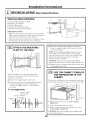
ADAPTING MICROWAVE
BLOWER FOR OUTSIDE
BACK EXHAUST
[]Remove and that holds blower motor
save screw
to microwave.
Blower Motor
_" - _ Blower Motor
v .,_ Screw
Careflflly pull out the blower unit. The wires
will extend far enough to allow you to adjust
the blower unit.
EndA
17

Installation Instructions
ADAPTING MICROWAVE
BLOWER FOR OUTSIDE
BACK EXHAUST (cont.)
[] Roll the blower" unit 90 °
Before Rotation After Rotation
Microwave
Backof
Microwave
Rotate blower unit counterclockwise 180 ° .
Before Rotation
Back of
Microwave
After Rotation
Back of
Microwave
[]Gently remove the wires from the
grooves.
Reroute the wires through grooves on other side
of the blower unit.
Before Rerouting After Rerouting
Wires Routed ThroughRight Side Wires Routed Through Left Side
_6_ Roll the blower unit 90 ° so that fan blade
openings are facing out the back of the
microwave.
Before Rolling
Microwave
After Rolling
Back of
Microwave
[]Place the blower unit back into the opening.
EndA
End
CAUTION: Do not pull or stretch the blower
unit wiring. Make sure the wires are not
pinched, and that they are properly secured.
NOTE: The blower unit exhaust
openings should match exhaust
openings on rear of microwave oven.
[ ecure the blower unit to the microwave with
the original screw.
Blower Plate
I _ Backof
,!_ Microwave
Blower Motor
Screw
[]Replace the blower in theplate
same
position
as before with the screw. Make sure the screw
is tight.
[]Attach the exhaust the of theadaptor
to Fear
oven by sliding it into the guides at the top
center of the back of the oven.
Adaptor
Backof
Microwave
o
Locking Tabs
Guide
Guide
Push in securely until it is in the lower locking
tabs. Take care to assure that the damper hinge
is installed so that it is at the top and that the
damper swings freely.
18

Installation Instructions
MOUNT THE MICROWAVE
OVEN
FOR EASIER INSTALLATION AND PERSONAL
SAFETY, WE RECOMMEND THAT TWO PEOPLE
INSTALL THIS MICROWAVE OVEN.
IMPORTANT: Do not grip or use handle
during installation.
NOTE: If your cabinet is metal, use the nylon
grommet around the power" cord hole to prevent
cutting of the cord.
NOTE: We recommend using filler blocks if the
cabinet front hangs below the cabinet bottom shelf.
IMPORTANT: If filler blocks are not
used, case damage may occur from
overtightening screws.
NOTE: When mounting the
microwave oven, thread
power cord through hole in
bottom of top cabinet. Keep
it tight throughout Steps
1-3. Do not pinch cord or"
lift oven by pulling cord.
[]Lift tilt it
microwave,
forward, and hook
slots at back bottom
edge onto four lower
tabs of mounting
plate.
[]Rotate fl'ont of
oven
up against cabinet
bottom.
[]Insert a self-aligning screw through top center
cabinet hole. Temporarily secure the oven by
turning the screw at least two full turns after the
threads have engaged. (It will be completely
tightened later:) Be sure to keep power cord
tight. Be careful not to pinch the cord, especially
when mounting flush to bottom of cabinet.
Cabinet Front
Cabinet Bottom Shelf
FillerBlock
-_ Equivalent
to Depth
of Cabinet
Recess
Self-Aligning Screw
Microwave Oven Top
[]Attach the microwave oven to the top cabinet.
[] Insert 2 self-aligning screws
through outer top cabinet
holes. Turn two flfll turns on
each screw.
[]Tighten center
screw completely.
[] Tighten the outer two screws to the top of the
microwave oven. (While tightening screws, hold
the microwave oven in place against the wall and
the top cabinet.)
[] Install grease filters. See the Owner's Manual
packed with the microwave.
19

Installation Instructions
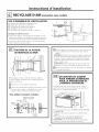
RECIRCULATING (Non-Vented Ductless)
INSTALLATION OVERVIEW
C1. Attach Mounting Plate to Wall
C3. Prepare Top Cabinet
C3. Check Blower Plate
C4. Mount the Microwave Oven
C5. Install or change Charcoal Filter
IMPORTANT NOTES:
• Make sure the screws for the blower motor and blower
plate are securely tightened when they are reinstalled.
This will help to prevent excessive vibration.
• Make sure the motor wiring has been properly routed
and secured, and that the wires are not pinched.
ATTACH THE MOUNTING
PLATE TO THE WALL
Attach the plate to the wall using toggle bolts.
At least one wood screw must be used to attach
the plate to a wall stud.
[]Remove the from the bolts.toggle wings
Insert the bolts into the mounting plate through
the holes designated to go into drywall and
reattach the toggle wings to 3/4" (19 mm) onto
each bolt.
To use toggle bolts:
Mounting
Plate,
Spacing for Toggles
More Than Wall
÷l_-_.i_,----Thickness
I
lToggle Wings
Bolt End
]Place the mounting plate against the wall and
insert the toggle wings into the holes in the wall
to mount the plate.
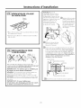
NOTE: Before tightening toggle bolts and wood
screw, make sure the tabs on the mounting plate
touch the bottom of the cabinet when pushed flush
against the wall and that the plate is properly
centered under the cabinet.
CAUTION: Be careful to avoid pinching fingers
between the back of the mounting plate and the wall.
Tighten all bolts. Pull the plate away from the wall
to help tighten the bolts.
I-_ USE TOP CABINET TEMPLATE
FOR PREPARATION OF TOP
CABINET
You need to drill holes for the top support screws and
a hole large enough for the power cord to fit through.
• Read the instructions on the TOP CABINET
TEMPLATE.
• Tape it underneath the top cabinet.
• Drill the holes, following the instructions on the
TOP CABINET TEMPLATE
CAUTION: Wear safety goggles when drilling holes
in the cabinet bottom.
2O
Page is loading ...
Page is loading ...
Page is loading ...
Page is loading ...
Page is loading ...
Page is loading ...
Page is loading ...
Page is loading ...
Page is loading ...
Page is loading ...
Page is loading ...
Page is loading ...
Page is loading ...
Page is loading ...
Page is loading ...
Page is loading ...
Page is loading ...
Page is loading ...
Page is loading ...
Page is loading ...
Page is loading ...
Page is loading ...
Page is loading ...
Page is loading ...
Page is loading ...
Page is loading ...
Page is loading ...
Page is loading ...
Page is loading ...
Page is loading ...
Page is loading ...
Page is loading ...
Page is loading ...
Page is loading ...
Page is loading ...
Page is loading ...
Page is loading ...
Page is loading ...
Page is loading ...
Page is loading ...
Page is loading ...
Page is loading ...
Page is loading ...
Page is loading ...
Page is loading ...
Page is loading ...
Page is loading ...
Page is loading ...
Page is loading ...
Page is loading ...
-
 1
1
-
 2
2
-
 3
3
-
 4
4
-
 5
5
-
 6
6
-
 7
7
-
 8
8
-
 9
9
-
 10
10
-
 11
11
-
 12
12
-
 13
13
-
 14
14
-
 15
15
-
 16
16
-
 17
17
-
 18
18
-
 19
19
-
 20
20
-
 21
21
-
 22
22
-
 23
23
-
 24
24
-
 25
25
-
 26
26
-
 27
27
-
 28
28
-
 29
29
-
 30
30
-
 31
31
-
 32
32
-
 33
33
-
 34
34
-
 35
35
-
 36
36
-
 37
37
-
 38
38
-
 39
39
-
 40
40
-
 41
41
-
 42
42
-
 43
43
-
 44
44
-
 45
45
-
 46
46
-
 47
47
-
 48
48
-
 49
49
-
 50
50
-
 51
51
-
 52
52
-
 53
53
-
 54
54
-
 55
55
-
 56
56
-
 57
57
-
 58
58
-
 59
59
-
 60
60
-
 61
61
-
 62
62
-
 63
63
-
 64
64
-
 65
65
-
 66
66
-
 67
67
-
 68
68
-
 69
69
-
 70
70


Frigidaire FMV152KQA Installation guide
- Category
- Microwaves
- Type
- Installation guide
Ask a question and I''ll find the answer in the document
Finding information in a document is now easier with AI
in other languages
Related papers
-
Electrolux EI30BM6CPSB Installation guide
-
Frigidaire CFMV157GSA Installation guide
-
-
GE 1600 Series User manual
-
GE 1800 Series Installation guide
-
Frigidaire FMV157GB Installation guide
-
Samsung FFMV162LS User manual
-
GE 1800 Series Installation guide
-
Frigidaire 40180093700 Installation guide
-
Crosley FGMV176NTFC Installation guide
Other documents
-
Kenmore Elite 79080373310 Installation guide
-
-
-
Maytag MMV4205BAS - 2.0 cu. Ft. Microwave Oven Owner's manual
-
GE JVM3162DJBB Installation guide
-
Universal/Multiflex (Frigidaire) CMWV150KWA Installation guide
-
Haier HMV1630DBBB Installation guide
-
-
 Kenmore Elite 36363694301 Installation guide
-
GE PSA2200RWW Operating instructions
