KLUS MICRO-HG Operating instructions

Category
Strip lights
Type
Operating instructions

KLUS MICRO-HG is an adjustable LED profile capable of housing a variety of LED strips for various lighting applications. Its compact size makes it suitable for under-cabinet and cove lighting. Installation is simple with the included mounting brackets, allowing for easy attachment to surfaces. The profile also features end caps and covers for a clean and professional finish, and can be cut and drilled to accommodate specific requirements.

KLUS MICRO-HG is an adjustable LED profile capable of housing a variety of LED strips for various lighting applications. Its compact size makes it suitable for under-cabinet and cove lighting. Installation is simple with the included mounting brackets, allowing for easy attachment to surfaces. The profile also features end caps and covers for a clean and professional finish, and can be cut and drilled to accommodate specific requirements.

MICRO-HG – mounting instructions
*The full range of accessories and electronics is available at www.KlusDesign.com
www.KlusDesign.com
NOTE! All LED tapes must be connected to a 12 V or 24 V power supply.
IMPORTANT: Not all possible mounting procedures are presented here.
More mounting procedures and related accessories can be found at www.KlusDesign.com.
Drawings of extrusions and accessories in these instructions are simplied and only
approximate the actual shapes.
1
1. MICRO-H prole (Ref. C1419)
2. End cap*
3. Gland*
4. Block*
5. Screw
6. Mounting bracket*
7. LED strip*
8. Cover*
9. Power supply (12 V / 24 V)*
1.
5.
2.
3.
2.
7.
6.
8.
9.
5.
6.
4.
www.KlusDesign.com 2
MICRO-HG – mounting instructions
Screw the mounting brackets (6) to the
surface, using appropriate screws (5).
It is recommended to use the following
amounts of brackets:
2 pcs. for 1m of the prole
4 pcs. for 2m of the prole
5 pcs. for 3m of the prole
a. Drill a hole in the prole (1) with
a diameter adapted to the gland (3)
used.
b. Insert the gland in the hole.
Cut the cover (8) so that
it is 10 mm / 0.39” shorter than
the prole.
Adhere the LED strip (7), wlead the wire
through the gland. Mount the end caps
(2) and the cover (8).
I
1.
5.
3.
6.
5.
6.
II
III
a. b.
8.
7.
2.
2.
-10 mm / 0.39”
www.KlusDesign.com 3
MICRO-HG – mounting instructions
Connect the cable to the power supply
(9) and mount the prole on the
mounting brackets as shown on the
drawing.
In order to disassemble the prole,
move it perpendicularly to its axis and
gently bend it away from the surface as
shown on the drawing.
DISASSEMBLY
IV
9.
www.KlusDesign.com 4
MICRO-HG – mounting instructions
Before the nal installation place the
assembled xture next to the mounting
brackets, so it is at its desired level. Place
the block (4) right over the mounting
bracket. It will prevent the xture from
sliding down. Finally mount the prole to
the surface.
VERTICAL MONTAGE
4.
Table of contents
Cutting and drilling...................................................................................................................................................................................................
Adhering and connecting LED strips..................................................................................................................................................................
Attaching covers and end caps...........................................................................................................................................................................
Sealing the extrusion................................................................................................................................................................................................
Connecting extrusions using ZM connectors..........................................................................................................................................
p.2
p.3
p.4
p.5
p.6
1
www.KlusDesign.com
General instructions
for an exemplary LED extrusion
- 2mm
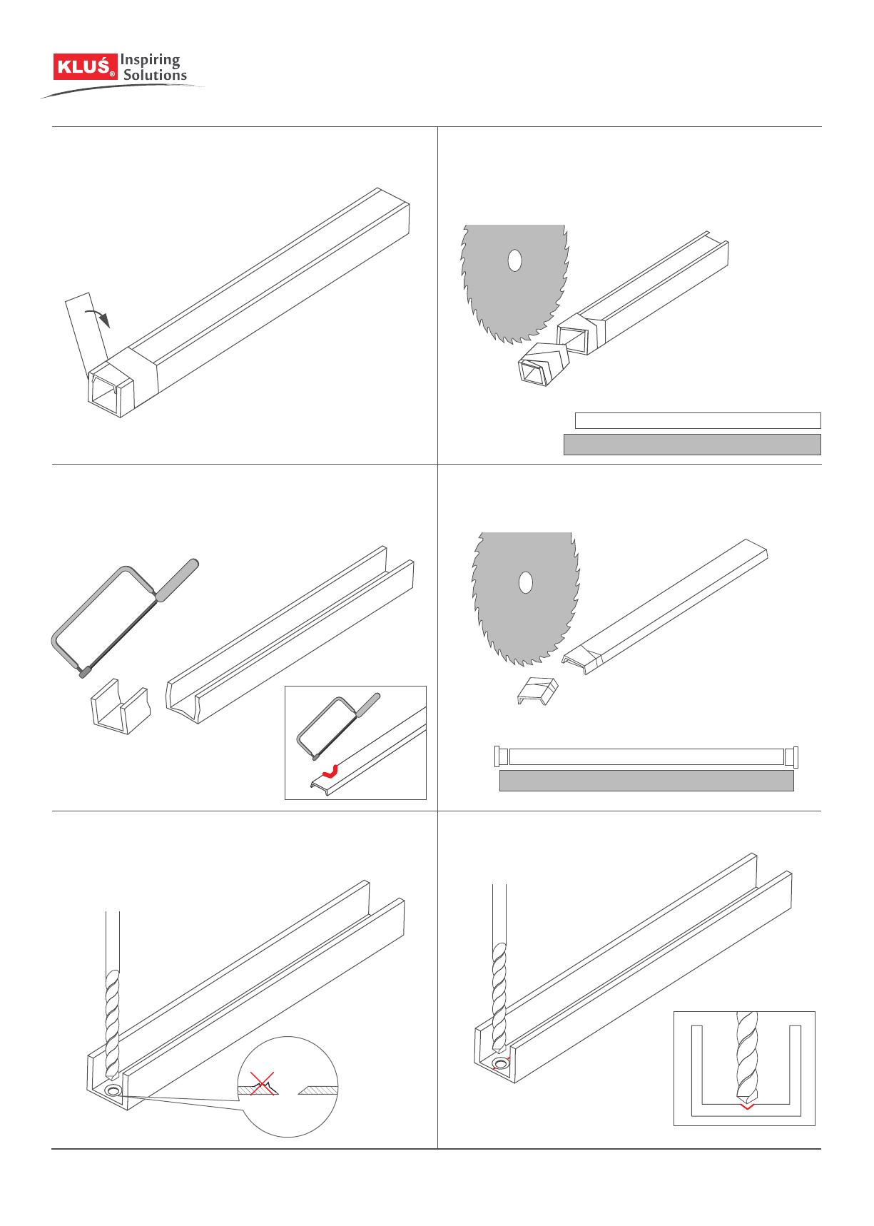
1. Before cutting the extrusion with the cover, secure the cutting point
with self-adhesive tape.
NOTE! For some extrusions there are dedicated end caps that require
adequate shortening of the cover.
NOTE! Low precision cutting of the extrusion and cover can be done with a
hand saw, however, uneven, jagged edges will remain, and the covers may
break.
2. Use a mechanical saw to cut.
NOTE! It is recommended that the cover be cut 2 mm shorter than the
extrusion to account for its thermal expansion.
3. Drill a hole in the extrusion in the selected place.
NOTE! Make sure that there are no burrs around the hole after drilling as they
can damage the LED strip or cable.
NOTE! Some extrusions feature one or more special grooves that make it easier
to start drilling.
2
www.KlusDesign.com
Cutting and drilling
+/-
1. Remove the protective layer of the LED strip.
4. Connect the LED strips with wires by soldering.
3. Lead the power cable through the drilled hole.
2. Attach the tape in the extrusion using the adhesive provided on the LED
strip.
NOTE! The tape must not be bent or peel o the surface.
OPTIONALLY: The LED strips can also be connected using a system of
LED strip connectors. More information at www.klusdesign.com
OPTIONALLY: The power cords can be led out from one pole of a given strip. This
method is used to power suspended lighting xtures.
3
www.KlusDesign.com
Adhering and connecting LED strips
1. . Insert the tip of the cover into the extrusion.
3. Insert an end cap into the edge of the extrusion. Individual extrusions have a
shape that allows easy installation of dedicated end caps.
NOTE! Some end caps require an adequately shortened cover. This should be
taken into account when cutting the extrusion and the cover.
OPTIONALLY: Short sections, can also be inserted from the edge of the
extrusion.
2. Press in the subsequent sections of the cover. Be careful not to bend or
break the wings of the cover.
OPTIONALLY: It is recommended to attach the end caps to the extrusion
with use of glue.
OPTIONALLY: Power cables can be run through the end caps in which case the
extrusion does not need to be drilled through.
4
www.KlusDesign.com
Attaching covers and end caps
1. Clean dust and dirt from the extrusion and accessories.
4. Apply a second layer of silicone on the extrusion walls and the end caps.
3. Apply a silicone layer to the bottom of the prole and embed the LED strip
in it.
NOTE: The LED strip must have separate protection against moisture.
We recommend a silicone sleeve or heat shrink tubing if the strip in the sleeve
does not t into the extrusion.
2. Attach the end caps with glue.
5. Remove the excess silicone with a rectangular tool (e.g. a piece of
cardboard), taking care not to damage the tape. The silicone layer must be
even and must not obscure the LEDs.
6. Insert the cover.
5
www.KlusDesign.com
Sealing the prole
1. Slide the connectors into the small locks of the extrusion. 2. Tighten the two pressure screws in each connector with an Allen wrench.
3. Slide the other half of the extrusion onto the connectors and tighten the
pressure screws with an Allen wrench.
6
www.KlusDesign.com
Connecting proles using ZM connectors
  • Page 1 1
  • Page 2 2
  • Page 3 3
  • Page 4 4
  • Page 5 5
  • Page 6 6
  • Page 7 7
  • Page 8 8
  • Page 9 9
  • Page 10 10

KLUS MICRO-HG Operating instructions

Category
Strip lights
Type
Operating instructions

KLUS MICRO-HG is an adjustable LED profile capable of housing a variety of LED strips for various lighting applications. Its compact size makes it suitable for under-cabinet and cove lighting. Installation is simple with the included mounting brackets, allowing for easy attachment to surfaces. The profile also features end caps and covers for a clean and professional finish, and can be cut and drilled to accommodate specific requirements.

Ask a question and I''ll find the answer in the document

Finding information in a document is now easier with AI