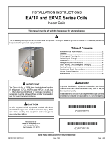
Lennox 507167-02 User manual

Type
User manual

The Lennox 507167-02 is an indoor evaporator coil designed for upflow applications. It features a factory-installed HFC-410A fixed orifice metering device or an externally equalized factory-installed HFC-410A check/expansion valve, depending on the model. The coil is available cased or uncased, with a maximum service temperature of 500°F for the drain pan. It is compatible with specific furnaces, air handlers, and line sets as specified in the Product Specification bulletin (EHB).

The Lennox 507167-02 is an indoor evaporator coil designed for upflow applications. It features a factory-installed HFC-410A fixed orifice metering device or an externally equalized factory-installed HFC-410A check/expansion valve, depending on the model. The coil is available cased or uncased, with a maximum service temperature of 500°F for the drain pan. It is compatible with specific furnaces, air handlers, and line sets as specified in the Product Specification bulletin (EHB).

Page 1
THIS MANUAL MUST BE LEFT WITH THE
HOMEOWNER FOR FUTURE REFERENCE
WARNING
Improper installation, adjustment, alteration, service
or maintenance can cause property damage, personal
injury or loss of life. Installation and service must be
performed by a licensed professional HVAC installer or
equivalent, service agency, or the gas supplier.
IMPORTANT
The Clean Air Act of 1990 bans the intentional venting of
refrigerant (CFCs, HCFCs and HFCs) as of July 1, 1992.
Approved methods of recovery, recycling or reclaiming
must be followed. Fines and/or incarceration may be
levied for noncompliance.
CAUTION
As with any mechanical equipment, contact with sharp
sheet metal edges can result in personal injury. Take
care while handling this equipment and wear gloves and
protective clothing.
IMPORTANT: Special procedures are required for clean-
ing the aluminum coil in this unit. See page 7 in this in-
struction for information.
General Information
The CX35 upow evaporator coils are available cased only.
The C35 coil is available cased or uncased and includes
a factory-installed HFC-410A xed orice (RFC) metering
device that must be replaced if the system match with the
coil requires a eld-installed check/expansion valve.
INSTALLATION
INSTRUCTIONS
INDOOR COILS
507167-02 (0655942-13)
7/2023
C35 / CX35 Series Coils
The CX35 coil includes an externally equalized factory-in-
stalled HFC-410A check/expansion valve.
The coil drain pan has a maximum service temperature
of 500°F. The drain pan must be at least 2" away from a
standard gas-red furnace heat exchanger and at least
4" away from any drum-type or oil-red furnace heat ex-
changer. Closer spacing may damage the drain pan and
cause a leak.
Refer to the Product Specication bulletin (EHB) for the
proper use of these coils with specic furnaces, air han-
dlers and line sets.
These instructions are intended as a general guide and
do not supersede local or national codes in any way. Au-
thorities who have jurisdiction should be consulted before
installation.
Shipping and Packing List
Package 1 of 1 contains:
C35
1 – Evaporator coil
1 – Patch plate with nameplate label (uncased coils only)
1 – Metering device label (uncased coils only)
CX35
1 – Evaporator coil
Check the components for shipping damage; if found, im-
mediately contact the last carrier.
Table of Contents
General Information .......................................................1
Shipping and Packing List .............................................1
Model Number Identication ...........................................2
C35 Optional Adjustable Coil Adapter/Seal Applications .. 2
Releasing Air Charge .....................................................3
Installation .....................................................................3
Refrigerant Line Connections ........................................ 3
Blower Speed Selection ................................................6
Maintenance ..................................................................7
Page 2
Model Number Identication
2
C 35 36-A-F
Unit Type
C = Indoor Coil - Upflow
Series
Nominal Cooling Capacity
18/24 = 1.5/2 tons
24 = 2 tons
30 = 2.5 tons
30/36 = 2.5/3 tons
36 = 3 tons
48 = 3.5/4 tons
49 = 4 tons
50/60 = 4/5 tons
60 = 5 tons
Cabinet Width
A = 14-1/2 in.
B = 17-1/2 in.
C = 21 in.
D = 24-1/2 in.
Cabinet
F = Cased
(Furnaces with the same cabinet width letter designation
will physically match the corresponding indoor coil.)
Metering Device
2 = Factory-Installed RFC Orifice
6
X 35 36--F
Unit Type
C = Indoor Coil - Upflow
Series
Nominal Cooling Capacity
18/24 = 1.5/2 tons
24 = 2 tons
30 = 2.5 tons
30/36 = 2.5/3 tons
36 = 3 tons
48 = 3.5/4 tons
49 = 4 tons
50/60 = 4/5 tons
60 = 5 tons
Cabinet Width
A = 14-1/2 in.
B = 17-1/2 in.
C = 21 in.
D = 24-1/2 in.
Cabinet
F = Cased
(Furnaces with the same cabinet width letter designation
will physically match the corresponding indoor coil.)
Metering Device
6 = Factory-Installed Check/Expansion Valve
for HFC-410A Refrigerant (non-bleed port)
C
Refrigerant Type
X = HFC-410A
A
C35 Optional Adjustable Coil Adapter / Seal Applications
slioC desacnU D26-53C dna D06-53CslioC desacnU C26-53C hguorht A81-53C
FURNACE
PLENUM
UNCASED
COIL
FURNACE
PLENUM
ADJUSTABLE COIL
ADAPTOR/SEAL
(Optional for
Uncased Coil)
UNCASED
COIL
ADJUSTABLE COIL
ADAPTOR/SEAL
(Optional for
Uncased Coil)
ACCESS PANEL
ACCESS PANEL
PIPING PATCH
PLATE
(Furnished
with coil)
PIPING PATCH
PLATE
(Furnished
with coil)
Page 3
FRONT VIEW SIDE VIEW
193/4 (502)
173/4 (451)
1
(25)
1
(25)
3/4
(19)
23/4
(70) 23/4
(70)
141/2 (368) to 247/8 (632)
9 (228) to 193/8 (492)
Opening
Opening
ADJUSTABLE COIL ADAPTOR/SEAL DIMENSIONS inches
(mm)
Frame Te lescopes To
Accommodate Various
Furnace Openings
Tab may be bent up 90° for
centering of smaller coils.
Ta b
ADJUSTABLE COIL ADAPTOR/SEAL DETAIL
Releasing Air Charge
CAUTION
The coil is shipped from the factory pressurized with dry
air. Pierce a hole in the rubber plug that seals the vapor
line to relieve the pressure before removing the plugs.
NOTE - If there is no pressure released when the vapor
line rubber plug is pierced, check the coil for leaks before
continuing with the installation.
The C35 and CX35 coils are shipped with a 10 + 3 psi dry
air holding charge. Puncture the suction line rubber plug
to release the charge. Remove the rubber plug. Ensure
that the coil is void of pressure.
Installation
WARNING
Risk of explosion or re.
Can cause injury or death.
Recover all refrigerant to relieve pressure before
opening the system.
Install the furnace or air handler according to the installa-
tion instructions provided with the unit.
Position the cased coil on top of the furnace or air handler
cabinet and secure it using eld-provided screws.
NOTE - If the coil is to be installed on an oil furnace, it may
be necessary to install a eld-installed transition between
the furnace and the coil to prevent airow restriction and
possible damage to the coil drain pan. See the oil furnace
installation instructions for details.
NOTE - The coil cabinet has six screw clearance holes
which should be aligned with the furnace engagement
holes. Secure the coil cabinet to the furnace or air handler
using six eld-provided #8 X 1" screws.
Refrigerant Line Connections
LINE SIZES
The refrigerant line sets should be sized according to the
recommendations given in the air conditioner unit instal-
lation instructions. Use either table 1 or 2 to determine
correct braze connection sizes. A eld-provided adapter
may be required to match line set connections.
Table 1. Refrigerant Line Connections – Model C35
Model Number Suction Liquid
18/24-2F
24-2F
30-2F
30/36-2F
36-2F
3/4 Inch
3/8 Inch
48-2F
49-2F
50/60-2F
60-2F
7/8 Inch
Page 4
Table 2. Refrigerant Line Connections – Model CX35
Model Number Suction Liquid
18/24-6F
24-6F
30-6F
30/36-6F
36-6F
3/4 Inch
3/8 Inch
48-6F
49-6F
50/60-6F
60-6F
7/8 Inch
REPLACEMENT PARTS
If replacement parts are necessary, order kit 69J46. The
kit includes:
10 – Brass nuts for liquid line assemblies
20 – Teon rings
10 – Liquid line orice housings
10 Liquid line assemblies
TEFLON RINGS (20)
BRASS NUTS (10)
LIQUID LINE ASSEMBLIES
(INCLUDES STRAINER) (10)
LIQUID LINE ORIFICE HOUSINGS (10)
LIQUID LINE
ASSEMBLY
COPPER
TUBE
PISTON
RETAINER
STRAINER
FIGURE 1. 69J46 Kit Components
BRAZING GUIDELINES
Use a silver alloy brazing rod (5 or 6 percent silver alloy
for copper-to-copper connections or 45 percent silver al-
loy for copper-to-brass or copper-to-steel connections).
Before making brazed connections, place a eld-provided
heat shield, such as a wet rag, against the unit cabinet
and around the piping stubs, expansion valve and sens-
ing bulb. The heat shield must be in place to prevent heat
damage during brazing. See gure 2.
WATER-
SATURATED
RAGS
PLACE A WET RAG AGAINST
COIL CABINET AND AROUND
THE SUCTION LINE
CONNECTION.
BRAZE CONNECTION. ALLOW
PIPE TO COOL BEFORE
REMOVING WET RAG.
1
2
FIGURE 2. Braze Refrigerant Lines
SUCTION LINE CONNECTION
Use the following procedure to connect the suction line to
the indoor coil:
1 - Remove rubber plug from the stubbed connection.
2 - Position the properly sized refrigerant piping and
make the brazed connection following the brazing
guidelines.
3 - Do not remove the water-saturated rags from the
cabinet and piping until the piping has cooled
completely.
C35 Suction Line Equalizer Fitting
Remove the copper are seat bonnet if present from the
male equalizer line tting (see gure 3).
IMPORTANT
When removing the are nut, ensure that the copper
are seal bonnet is removed as illustrated in gure 3.
SUCTION LINE
FLARE NUT
REMOVE AND DISCARD FLARE
SEAL BONNET IF PRESENT
MALE BRASS EQUALIZER LINE
FITTING
FLARE
SEAL CAP
OR
FIGURE 3. C35 Suction Line Male Equilizer Line
Fitting Modications
C35 LIQUID LINE CONNECTION
NOTE - C35 coils are shipped with a factory-installed
HFC-410A xed orice (RFC) metering device. Some sys-
tem matches with this coil require use of a check/expan-
sion valve.
If the system match requires an HFC-410A check/ex-
pansion valve, the factory-installed refrigerant metering
orice must be removed and a check/expansion valve
eld-installed before the liquid line connections are made.
The xed orice device must be removed BEFORE a
check/expansion valve is installed if necessary. CX35
coils include a factory-installed HFC-410A check/expan-
sion valve.
C35 Fixed Orice Removal (If necessary)
1 - Remove the coil access and plumbing panels.
2 - Remove any shipping clamps that secure the liquid
line and distributor assembly.
3 - Using two wrenches, disconnect the liquid line stub
from the orice housing. Take care not to twist or
damage the distributor tubes during this process.
4 - Remove and discard the existing orice, valve stem
assembly (if present) and Teon ring as illustrated
in gure 4.
5 - Retain brass nut to be used later with the liquid line
assembly.
Page 5
O-RING
REMOVE AND DISCARD
WHITE TEFLON SEAL
STRAINER
DISTRIBUTOR
TUBES
LIQUID LINE
STUB
ORIFICE HOUSING
(REMOVE ORIFICE
FROM INSIDE OF
HOUSING)
FIGURE 4. Typical Fixed Orice Removal
C35 Expansion Valve / Liquid Line Installation
Some system matches for the C35 coil require a check/
expansion valve. The expansion valve must be installed
external to the indoor coil cabinet. Refer to the instructions
provided with the expansion valve kit for proper installa-
tion of the valve and sensing bulb.
See the C35 Product Specication bulletin (EHB) for ap-
proved expansion valve match-ups and application infor-
mation.
1 - After the expansion valve, equalizer line and sensing
bulb have been installed per the kit instructions,
braze the properly sized refrigerant piping into
place. Carefully follow brazing guidelines and use
wet rags to prevent heat damage.
2 - Do not remove the water-saturated rags from the
cabinet and piping until the piping has cooled
completely.
NOTE - To prevent any possibility of water damage, prop-
erly insulate all parts of the expansion valve assembly that
may sweat due to temperature dierences between the
valve and its surrounding ambient temperatures.
CX35 LIQUID LINE CONNECTION
CX35 coils include a factory-installed HFC-410A check/
expansion valve metering device.
Connect the properly sized eld-provided liquid line to the
liquid line stub as shown in gure 5 using one of the fol-
lowing procedures:
1 - Position the properly sized refrigerant piping and
make the brazed connection following the brazing
guidelines.
2 - Do not remove the water-saturated rags from the
cabinet and piping until the piping has cooled
completely.
OR
1 - Cut the copper liquid line on a vertical or horizontal
section. Use a eld-provided coupling to join the
properly sized eld-provided refrigerant piping
and and the liquid line stub on the coil. Follow the
brazing guidelines.
2 - Do not remove the water-saturated rags from the
cabinet and piping until the piping has cooled
completely.
COIL LIQUID LINE
UNBRAZE AT FITTING
CUT TWO INCHES UP
CUT TWO INCHES OUT
COUPLING
SWEDGED CONNECTION
or
NOTE - Use the coupling at either of the two cut connections.
REMOVE AND DISCARD
VALVE STEM ASSEMBLY
(IF PRESENT)
FIGURE 5. CX35 Liquid Line Connections
Leak Testing, Evacuating and Charging
Refer to the outdoor unit instruction for leak testing, evac-
uating and charging procedures. Always leak check entire
system before charging.
Sealing Ducts
WARNING
There must be an airtight seal between the bottom of the
furnace and the return air plenum. Use berglass sealing
strips, caulking, or equivalent sealing method between
the plenum and the air handler cabinet to ensure a tight
seal. Return air must not be drawn from a room where
the air handler or any gas-fueled appliance (i.e., water
heater), or carbon monoxide-producing device (i.e.,
wood replace) is installed.
The coil cabinet MUST be sealed after installation to en-
sure against air leaks, which can impact system perfor-
mance. The material, and method, used should be ca-
pable of enduring the range of temperature and humidity
levels expected in the specic install location.
Ensure that the duct is secured and all joints are properly
sealed to the coil cabinet anges.
Condensate Drain Connections
IMPORTANT
After removal of drain pan plug(s), check drain hole(s)
to verify that drain opening is fully open and free of any
debris. Also check to make sure that no debris has fallen
into the drain pan during installation that may plug up the
drain opening.
MAIN DRAIN
Connect the main drain and route drain tubing downward
to drain line or sump. Do not connect drain to a closed
waste system. See gure 6 for typical drain trap congu-
ration.
Page 6
OVERFLOW DRAIN
It is recommended that the overow drain stub be con-
nected to an overow drain line for all units. If the overow
drain is not connected to a drain line, it must be plugged
with the provided cap.
CONDENSATE DRAIN RECOMMENDATIONS
The following practices are recommended to ensure bet-
ter condensate removal:
Main and overow drain lines should NOT be smaller
than both drain connections at drain pan.
Overow drain line should run to an area where home-
owner will notice drainage.
It is recommended that the overow drain line be vented
and a trap installed. Refer to local codes.
ABOVE
FINISHED
SPACE?
OVERFLOW DRAIN LINE
ALWAYS RUN AN OVERFLOW DRAIN LINE. IF NOT POSSIBLE TO
ROUTE OVERFLOW DRAIN LINE, INSTALL LOW VOLTAGE
OVERFLOW SWITCH KIT. WIRE KIT TO SHUT DOWN
COMPRESSOR PER INSTRUCTIONS.
NO
YES
OEM CATALOG#
X3169 CLEAN OUT
VENT
PRESS IN
(DO NOT GLUE)
VENT MUST EXTEND
ABOVE HEIGHT OF
COIL DRAIN PAN BY
TWO INCHES
1” X 3/4” X 3/4”
REDUCING
TEE WITH
PLUG
OEM CATALOG
NUMBERS* P-TRAP
49P66, J-TRAP #
91P90 OR ANY PVC
SCH 40 P- OR
J-TRAP 3/4”
OVERFLOW
DRAIN
OPTIONAL
SAFETY
PAN
COIL DRAIN PAN
WHEN A COIL IS LOCATED ABOVE A FINISHED SPACE, A 3/4” SECONDARY DRAIN LINE
MUST BE:
CONNECTED TO SECONDARY DRAIN PAN
OR
●CONNECTED TO THE OVERFLOW DRAIN OUTLET OF THE AIR HANDLER DRAIN PAN.
TRAPS MUST BE DEEP ENOUGH TO OFFSET MAXIMUM STATIC DIFFERENCES
GENERALLY, TWO INCHES.
DRAIN LINE SHOULD
SLOPE A MINIMUM OF
ONE INCH PER 10 FT.
NOTE WHEN A AIR HANDLER IS LOCATED ABOVE A FINISHED SPACE THE SECONDARY
DRAIN PAN MUST HAVE A LARGER FOOTPRINT THAN THE AIR HANDLER.
MAIN
DRAIN
TO APPROVED
DRAIN
FOR NEGATIVE PRESSURE COILS (BLOWER
AFTER COIL) TRAPS ARE REQUIRED ON ALL
DRAIN LINES CONNECTED TO COIL.
COMPACT OVERFLOW SWITCH WITH 3/4” FEMALE SLIP INLET
AND MALE ADAPTER, TWO PART DESIGN FOR USE WHERE
OBSTRUCTIONS PREVENT DIRECT THREADING
SECONDARY
DRAIN PAN
2”
(51MM)
TRAP DEPTH
*OEM CATALOG # P-TRAP 49P66 REQUIRES A LARGER INSTALLATION SPACE THAN THE J-TRAP 91P90.
FIGURE 6. Typical Main and Overow Drain Installations
Blower Speed Selection
LEFT-HAND AIR
DISCHARGE (TOP VIEW)
TEST HOLES
AIR FLOW
FIGURE 7. Static Pressure Test
CAUTION
Take care when drilling test holes into the furnace ange
and the duct. Drill holes away from refrigerant piping.
Test holes should be drilled where specied in order to
avoid unit damage.
Proper air volume must be provided over the evaporator
coil. Select a blower motor speed tap that will provide 400
± 50 CFM per 12,000 Btuh of cooling capacity (wet coil).
A static pressure reading must be taken to see if the pres-
sure drop falls within the proper range.
To ensure accuracy, air must be read from below the coil
and above the coil. See gure 7 for an example to obtain
an accurate reading.
1 - Drill one 5/16" air test hole into the delta plate
between the coil slabs.
Page 7
2 - Drill one 5/16" air test hole into the duct above the
top of the coil.
3 - Connect the instrument for static pressure
measurement hoses to the air entering side of coil.
Insert the hoses so that 1/4" extends inside the duct
or end seal. Seal around holes with Permagum®.
4 - Turn on electrical power to the furnace and set the
thermostat to initiate a cooling demand.
5 - Tables 3 and 4 list air volumes and equivalent static
pressure readings for these units. Observe the
static pressure reading. If the reading is below the
required air volume, increase the blower speed;
if the reading is above the required air volume,
decrease the blower speed. Refer to the furnace
wiring diagram for blower speed settings.
6 - When the required static pressure readings are
obtained, remove the test hose lines and insert
snap hole plugs into test holes.
Table 3. Air Volume / Static Pressure Drop Across
Coil – Model C35
Cabinet
Vol: CFM
Drop: in. w.g.
Model Width in. Dry Wet
18 / 24A 14.5 600 .11 .17
14.5 800 .18 .25
18 / 24B 17.5 600 .11 .17
17.5 800 .18 .25
24A 14.5 800 .16 .18
24B 17.5 800 .16 .18
30A 14.5 1000 .18 .2
30B 17.5 1000 .18 .20
30 / 36A 14.5 1000 .19 .21
14.5 1200 .27 .30
30 / 36B 17.5 1000 .13 .16
17.5 1200 .17 .21
30 / 36C 21 1000 .13 .16
21 1200 .17 .21
36A 14.5 1200 .27 .30
36B 17.5 1200 .17 .21
48B 17.5 1400 .23 .24
17.5 1600 .30 .31
48C 21 1400 .13 .16
21 1600 .16 .20
49C 21 1600 .17 .22
50 / 60C 21 1600 .23 .29
60C 21 2000 .29 .34
60D 24.5 2000 .21 .27
Table 4. Air Volume / Static Pressure Drop Across
Coil – Model CX35
Cabinet
Vol: CFM
Drop: in. w.g.
Model Width in. Dry Wet
18 / 24A 14.5 600 .11 .17
14.5 800 .18 .25
18 / 24B 17.5 600 .11 .17
17.5 800 .18 .25
24A 14.5 800 .16 .18
24B 17.5 800 .16 .18
30A 14.5 1000 .18 .20
30B 17.5 1000 .18 .20
30 / 36A 14.5 1000 .19 .21
14.5 1200 .27 .30
30 / 36B 17.5 1200 .13 .16
17.5 1200 .17 .21
30 / 36C 21 1000 .13 .16
21 1200 .17 .21
36A 14.5 1200 .27 .30
36B 17.5 1200 .17 .21
48B 17.5 1400 .23 .24
17.5 1600 .30 .31
48C 21 1400 .13 .16
21 1600 .16 .20
49C 21 1600 .17 .22
50 / 60C 21 1600 .23 .29
60C 21 2000 .29 .34
60D 24.5 2000 .21 .27
Maintenance
NOTICE !
Failure to follow instructions will cause damage to
the unit.
This unit is equipped with an aluminum coil. Alu-
minum coils may be damaged by exposure to solu-
tions with a pH below 5 or above 9. The aluminum
coil should be cleaned using potable water at a mod-
erate pressure (less than 50psi). If the coil cannot
be cleaned using water alone, Lennox recommends
use of a coil cleaner with a pH in the range of 5 to 9.
The coil must be rinsed thoroughly after cleaning.
In coastal areas, the coil should be cleaned with po-
table water several times per year to avoid corrosive
buildup (salt).
A trained technician or service agency must perform main-
tenance and service on equipment. At the beginning of
each heating or cooling season, indoor coils should be
cleaned.
Do not use hydrouoric acid, alkaline, or similar chemicals
on coils. These chemicals are not necessary to dissolve
salt, and may damage the n coating. Acid washes are
used to dissolve oils and greases, which generally are not
present on most installations.
Page 8
4 - Spray the coil at a vertical angle of 30 to 45 degrees
with a constant stream of water at moderate
pressure. A pressure washer with a fan nozzle will
work best. Do not spray the coil from a horizontal
direction.
5 - Direct the spray so that any debris is washed out
of the coil and base pan. For most residential units,
hot water is not necessary.
NOTE - Attempting to back ush from the inside of the coil
will require removing parts from the unit, and it may be
very dicult to ush the whole coil surface. Attempting to
blow water through a coil will slow the water stream and
reduce the ushing action of the outer n surface.
6 - Replace the coil into the cabinet or plenum. Ensure
that you have followed the proper procedure for
routing and securing the refrigerant tubing.
IMPORTANT
Ensure that the distributor lines are not rubbing together
or kinked. All tubes must have enough clearance
from other metal parts. Use wire ties to secure tubes
to prevent movement that could cause the refrigerant
tubing to fail.
Alkaline washes are useful for dissolving oxides such as
zinc oxide, aluminum oxide, and iron oxide (rust). These
three oxides are more corrosion-resistant than base met-
als, so dissolving or removing them will cause an increase
in corrosion.
CLEANING THE COIL
1 - Remove the coil from the cabinet or plenum, and
take the coil to an appropriate place to clean it.
2 - Vacuum or brush the coil to remove matted
and surface debris from the ns. Use vacuum
attachments and /or brushes that are non-
destructive to ns.
3 - If oil deposits are present, spray the coil with a mild
household liquid detergent to soften deposits. Do
not leave the detergent on the coil for more than
10 minutes. Flush the coil thoroughly with potable
water.
NOTE - For units in coastal regions, fresh water will dis-
solve away any salt deposits. (Wash coils with fresh water
at least every six months.)
  • Page 1 1
  • Page 2 2
  • Page 3 3
  • Page 4 4
  • Page 5 5
  • Page 6 6
  • Page 7 7
  • Page 8 8

Lennox 507167-02 User manual

Type
User manual

The Lennox 507167-02 is an indoor evaporator coil designed for upflow applications. It features a factory-installed HFC-410A fixed orifice metering device or an externally equalized factory-installed HFC-410A check/expansion valve, depending on the model. The coil is available cased or uncased, with a maximum service temperature of 500°F for the drain pan. It is compatible with specific furnaces, air handlers, and line sets as specified in the Product Specification bulletin (EHB).

Ask a question and I''ll find the answer in the document

Finding information in a document is now easier with AI