GE/CADDX
NX-8e
INTRODUCTION
This Application Note describes how to interface a JDS STARGATE controller to a GE/CADDX NX-8, NX-6 or NX-4 or NX-8e
security system. The NX-8 can be expanded to 48 zones maximum. The NX-8e can be expanded to 192 zones maximum.
STARGATE supports the first 64 zones.
STARGATE takes full advantage of all GE/CADDX security functions including:
• Arm or disarm the system
• Home and Away modes
• Bypass or Unbypass zones
• Turn the keypad chime mode on and off
• Monitor and act upon partition and zone changes
• Automatically set the alarm panel’s clock
• Track the status of the security system
• Detect alarm conditions
• Detect zone trouble conditions
• User Number
• More
The GE/CADDX NX-8, NX-6 or NX-4 requires the optional NX-584 serial interface in order to communicate with Stargate.
The GE/CADDX NX-8e requires a P0003 adaptor kit to provide a serial connection.
Support for GE/CADDX NX panels requires Version 3.00 (or higher) Firmware/Software for the JDS STARGATE controller.
The GE/CADDX NX panel connects to COM2 or COM3 of STARGATE.
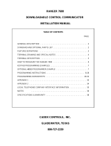
The typical configuration consists of the GE/CADDX NX-8 security panel w/ NX-584 serial interface or NX-8e security panel
with P0003 adaptor kit and at least one GE/CADDX LCD type keypad (for alarm system programming and backup for alarm
system control).
GE/CADDX NX-584
Serial Interface
STARGATE
DB9-RJ11
adaptor
6-conductor
DATA cable
Connection to GE/CADDX NX-8 Connection to GE/CADDX NX-8e
P0003 Adapter
(plugs into connector J11
on NX-8e circuit board -
red stripe toward back)
6-conductor
DATA cable
STARGATE STARGATE
GE/CADDX
NX-8
NX-584
Application Note 4.3
Interfacing STARGATE to a GE/CADDX
NX-8/6/4 or NX-8e Security System
APPLICATION NOTE 4.3
3 wire connection
to GE/Caddx panel
keypad terminals
STARGATE
DB9-RJ11
adaptor

INSTALLATION AND SETUP
Follow the steps described below to install and configure the system.
1) Install Security System
You must first install the security system; refer to the GE/CADDX documentation for details.
For the GE/Caddx NX-8, NX-6 or NX-4, you must also install an NX-584 serial interface board into the security system.
The NX-584 connects to the POS, GND, and DATA keypad
screw terminals on the GE/CADDX panel and provides the RS-232
serial interface (DB-9) that STARGATE connects to.
NOTE: The NX-584 has four jumpers (J7, J8, J9, J10)
that control the functions of the DB-9 serial port pins.
Leave the NX-584 jumpers in their default positions.
Jumpers J7 & J10 toward DB-9 serial connector (J6),
Jumpers J8 & J9 away from DB-9 serial connector.
The GE/CADDX NX-8e has built-in serial communication and does not require a NX584. Instead, use a ZCIF232 interface
adaptor kit to provide a serial connection. (See connection diagram on page 1)
We strongly recommend you get the security system up and running before connecting it to STARGATE.
This will reduce the likelihood of problems and make troubleshooting much easier.
2) Configure Security System Communication Settings
The GE/CADDX security system provides a variety of configurable settings that control how it works. These must be properly
set up before it can be used with STARGATE. The table below shows the required settings and the programming locations for
each. Refer to the GE/CADDX Installation Manual for further details on how to program these.
If your GE/CADDX security panel is set to its default settings, press * 8 9 7 1 3 7 2 # for NX-8/6/4 or * 8 9 7 1 3 0 # for NX-8e from
the Caddx keypad to begin programming. Then continue programming the following settings.
Set to ASCII Mode 0 1 1 _ _ _ _ _ _ _
Set to 9600 baud 1 1 _ _ _ 4 _ _ _ _
Enable Transitions 2 1 _ _ _ _ _ 6 7 _
Command/Request Enables 3 1 _ 2 _ 4 5 6 7 8
Request functions 3 2 1 2 3 _ _ _ _ _
3 3 _ _ _ _ _ _ _ _
Enable keypad functions 3 4 _ _ 3 4 5 6 7 8
(none)
NX584 Enabled 207 1 1 _ _ _ _ _ _ _
Set to 9600 baud 208 1 _ 2 _ _ _ _ _ _
Set to ASCII Mode 209 1 1 _ _ _ _ _ _ _
Enable Transitions 210 1 _ _ _ _ _ 6 7 _
Command/Request Enables 211 1 _ 2 _ 4 5 6 7 8
Request functions 211 2 1 2 3 _ _ _ _ _
211 3 _ _ _ _ _ _ _ _
Enable keypad functions 211 4 _ _ 3 4 5 6 7 8
(none)
NX-8/6/4
NX-8e
NX-584
DB-9
LEDS
J8
J10
J7
J9
J6
To
STARGATE
To
GE/CADDX
Keypad
Terminals
POS
COM
DATA
REQUIRED SETTING Location Segment Bits to turn ON
REQUIRED SETTING Location Segment Bits to turn ON

SECURITY SYSTEM COMMANDS
The following security system commands can be used as THEN - SECURITY actions anywhere in your schedule.
Arm partition in Home Mode
This command arms the partition(s) in the Home (Stay) mode. There will be separate check boxes on the screen for each
partition in your system. You can select any or all of the partitions to arm.
Arm partition
This command arms the partition(s) specified. There will be separate check boxes on the screen for each partition in your
system. You can select any or all of the partitions to arm.
Disarm partition
This command disarms the partition(s) specified. There will be separate check boxes on the screen for each partition in your
system. You can select any or all of the partitions to disarm. If an alarm is going off, this command will silence it.
Bypass zone
This command bypasses a particular zone.
Un-Bypass zone
This command un-bypasses a particular zone.
Turn partitions chime mode ON
This command turns on the chime mode for the partition(s) specified. There will be separate check boxes on the screen for
each partition in your system. You can select any or all of the partitions to turn on.
Turn partitions chime mode OFF
This command turns off the chime mode for the partition(s) specified. There will be separate check boxes on the screen for
each partition in your system. You can select any or all of the partitions to turn off.
Toggle partitions instant mode
This command toggles the “instant” mode for the partition(s) specified. There will be separate check boxes on the screen for
each partition in your system. You can select any or all of the partitions to control. If the partition instant mode is currently off,
it will turn on. If it is currently on, it will turn off.
Sound partitions Fire Panic
This command sounds the “fire panic” alarm for the partition(s) specified. There will be separate check boxes on the screen for
each partition in your system. You can select any or all of the partitions to sound.
Sound partitions Medical Panic
This command sounds the “medical panic” alarm for the partition(s) specified. There will be separate check boxes on the
screen for each partition in your system. You can select any or all of the partitions to sound.
Sound partitions Police Panic
This command sounds the “police panic” alarm for the partition(s) specified. There will be separate check boxes on the screen
for each partition in your system. You can select any or all of the partitions to sound.
Load user_VAR with User Number
This command loads the most recent User Number entered into the user_VAR. There will be separate check boxes on the
screen for each partition in your system. You can select any or all of the partitions.
INSTALLATION AND SETUP (cont’d)
3) Use a P0003 adapter kit to connect the GE/CADDX circuit board (connector J11) to Stargate’s COM2 or COM3.
4) Configure WinEVM Software:
· Open the Security System Configuration screen under the Define menu.
· In the “Security system type” box, select “CADDX NetworX”.
· In the “Serial Port Used” box, select the STARGATE serial port number the security system is connected to.
· For each zone, you can enter a descriptive name. This name will be used in your schedule.
Click OK. WinEVM will configure the STARGATE serial port for use with the GE/CADDX Security Panel.
At this point, you can use the IF and THEN SECURITY statements in your schedule.
Use the MegaController to monitor security panel activity to verify STARGATE is communicating with the security system properly. If
no activity is observed, click “Logging Messages” (above the MegaController Activity Log box) and verify SECURITY is selected.
If still no activity is observed: a) Remove power from the security system then reapply it. b) Verify the serial cable is properly
connected between STARGATE and the GE/CADDX panel. c) Be sure you have the correct cable type. d) Verify the parameters were
set up properly.

SECURITY SYSTEM CONDITIONS
The following security system conditions can be used as IF - SECURITY conditions anywhere in your schedule.
Transition Activated
At the start of every schedule pass, STARGATE will process the information the GE/CADDX security panel has sent.
Any changes to partitions or zones will cause an internal “transition” state to be set for that pass through the schedule,
the “transition” state will be cleared at the end of the schedule pass.
When the “Transition Activated” checkbox is selected, the IF condition will be TRUE when the condition goes active.
When not selected, the IF condition will be TRUE when the condition is active. This is best explained in an example:
EVENT: Partition Armed
If
SEC: Partition ARMED[Partion 1] TRANSITION
Then
LCD: Red LED ON [KP:ALL]
End
In the above example the LCD Keypads Red LED will be turned ON at the time the security panel becomes armed.
EVENT: Security Lights
If
SEC: Partition ARMED[Partion 1]
and Sunset SMTWTFS
Then
X10: F-1 Front Porch Lt ON
End
In this example the Front Porch light will turn ON if the security panel IS armed (as opposed to becomes armed) and
the time is Sunset. Note: if “Transition Activated” was used, the Security Lights event would trigger only if the security
panel became armed exactly at Sunset.
User Number
Events can be created based on the last user to arm or disarm the Caddx panel.
NOTE: If the same User Number is repeated, Stargate will not see the repeated User Number become true and
therefore not respond until a different User Number is received. To accommodate repeated User Numbers, add the
“Partition ARMED” or “Partition Not ARMED” condition. Example:
EVENT: Hall Light On for User 1
If
SEC: Partition Not ARMED[Partion 1]
and SEC: User Number is 1 [Partition 1]
Then
X10: F-2 Hall Lt ON
End

SECURITY SYSTEM CONDITIONS
The following security system conditions can be used as IF - SECURITY conditions anywhere in your schedule.
Partition ARMED
This condition is true if the specified partition is currently ARMED.
Partition ARMED & in Home Mode
This condition is true if the specified partition is currently armed in the Home (Stay) mode. It will be false if armed in the
Away mode or disarmed.
User Number
This condition is true if the specified User Number is the most recent to be entered.
Partition Not Armed
This condition is true if the specified partition is currently disarmed.
Partition is READY
This condition is true if the specified partition is currently ready to arm.
Partition is Not READY
This condition is true if the specified partition is currently not ready to arm.
Partition has alarm condition
This condition is true if the specified partition currently has an alarm condition.
Partition has no alarm condition
This condition is true if the specified partition currently does not have an alarm condition.
Partition chime mode is ON
This condition is true if the specified partition’s chime mode is currently on.
Partition chime mode is OFF
This condition is true if the specified partition’s chime mode is currently off.
Partition Entry Delay Active
This condition is true if the specified partition has its Entry Delay in progress.
Partition Entry Delay Not Active
This condition is true if the specified partition’s Entry Delay is not in progress.
Partition Exit Delay Active
This condition is true if the specified partition has its Exit Delay in progress.
Partition Exit Delay Not Active
This condition is true if the specified partition’s Exit Delay is not in progress.
Zone is faulted
This condition is true if the specified zone is currently faulted.
Zone is not faulted
This condition is true if the specified zone is not currently faulted.
Zone is bypassed
This condition is true if the specified zone is currently bypassed.
Zone is not bypassed
This condition is true if the specified zone is not currently bypassed.

SECURITY SYSTEM CONDITIONS (Cont’d)
Zone is in trouble condition
This condition is true if the specified zone is currently in a “trouble” condition.
Zone is not in trouble condition
This condition is true if the specified zone is not currently in a “trouble” condition.
Zone has alarm in memory
This condition is true if the specified zone has an alarm stored in its memory (i.e., this zone is currently or was
previously in an alarm condition).
Zone does not have alarm in memory
This condition is true if the specified zone does not have an alarm stored in its memory.
Any zone is faulted
This condition is true if any of the system zones are currently faulted.
Any zone is bypassed
This condition is true if any of the system zones are currently bypassed.
Any zone is in trouble condition
This condition is true if any of the system zones are currently in a “trouble” condition.
Any zone has an alarm in memory
This condition is true if any of the system zones currently have an alarm stored in memory.
CADDX Controls, Inc.
1420 North Main Street
Gladewater, TX 75646
(800) 727-2339
(903) 845-6811 (fax)
internet:
www.caddx.com
JDS Technologies
12200 Thatcher Court
Poway, CA 92064
(858) 486-8787
(858) 486-8789 (fax)
e-mail: [email protected]
internet: www.jdstechnologies.com
REFERENCES
/