Page is loading ...

CHROMA METER
CR-400/410
Instruction Manual
Advanced Test Equipment Rentals
www.atecorp.com 800-404-ATEC (2832)
®
E
s
t
a
b
l
i
s
h
e
d
1
9
8
1

Safety Symbols
The following symbols are used in this manual to prevent accidents which may occur as a result of
incorrect use of the instrument.
Denotes a sentence regarding a safety warning or note.
Read the sentence carefully to ensure safe and correct use.
Denotes a prohibited operation.
The operation must never been performed.
Denotes an instruction.
The instruction must be strictly adhered to.
Denotes an instruction.
Disconnect the AC adapter from the AC outlet.
Denotes a prohibited operation.
Never disassemble the instrument.
Notes on This Manual
• Copying or reproduction of all or any part of the contents of this manual without MINOLTA’s
permission is strictly prohibited.
• The contents of this manual are subject to change without prior notice.
• Every effort has been made in the preparation of this manual to ensure the accuracy of its contents.
However, should you have any questions or find any errors, please contact a Minolta-authorized
service facility.
• MINOLTA will not accept any responsibility for consequences arising from the use of the instru-
ment.

1
Safety Precautions
To ensure correct use of this instrument, read the following points carefully and adhere to them. After
you have read this manual, keep it in a safe place where it can be referred to anytime a question arises.
WARNING
(Failure to adhere to the following points may result in death or
serious injury.)
Do not use the instrument in places where
flammable or combustible gases (gasoline
etc.) are present. Doing so may cause fire.
Do not disassemble or modify the in-
strument or the AC adapter. Doing so
may cause a fire or electric shock.
Always use the AC adapter supplied as
a standard accessory or the optional AC
adapter, and connect it to an AC outlet
of the rated voltage and frequency. If the
AC adapters other than those specified
by MINOLTA are used, this may result
in damage to the unit, fire or electric
shock.
The instrument should not be operated if
it is damaged or AC adapter is damaged,
or if smoke or odd smells occur. Doing so
may result in a fire. In such situations, turn
the power OFF immediately, disconnect
the AC adapter from the AC outlet (or re-
move the batteries if they are used) and
contact the nearest Minolta-authorized ser-
vice facility.
If the instrument will not be used for a long
time, disconnect the AC adapter from the
AC outlet. Accumulated dirt or water on
the prongs of the AC adapter’s plug may
cause a fire and should be removed.
Do not connect or disconnect the AC
adapter with wet hands. Doing so may
cause electric shock.
Take special care not to allow liquid or
metal objects to enter the instrument.
Doing so may cause a fire or electric
shock. Should liquid or metal objects en-
ter the instrument, turn the power OFF im-
mediately, disconnect the AC adapter from
the AC outlet, and contact the nearest
Minolta-authorized service facility.
Do not dispose of batteries in fire, short
their terminals, apply heat to them, or
disassemble them. Also, do not recharge
them. Doing so may cause explosion or
heat generation, resulting in fire or in-
jury.
CAUTION
(Failing to adhere to the following points may result in injury
or damage to the instrument or other property.)
Do not perform measurement which the
measurement aperture directed towards
your face. Doing so may damage them.
Do not place the instrument on an un-
stable or sloping surface. Doing so may
result in its dropping or overturning,
causing injury. Take care not to drop the
instrument when carrying it.
Do not use batteries other than those speci-
fied by MINOLTA. When installing bat-
teries in the instrument, make sure that
they are correctly oriented according to the
(+) and (-) marks. Failure to adhere to these
instructions may cause batteries to explode
or leakage of electrolytes, resulting in fire,
injury or air pollution.
When using an AC adapter, make sure
that the AC outlet is located near the in-
strument and that the AC adapter can be
connected to and disconnected from the
AC outlet easily.

2
Chapter 1 Measuring Head 1 (P.21- )
Chapter 2 Measuring Head 2 (P.53- )
Chapter 3 Data Processor (P.57- )
When using the measuring head alone.
When using the measuring head separately from the data processor after setting.
• The measuring head cannot be set by itself, but functions which run by setting the head using the
optional CR-400 utility software CR-S4w or the Color data software ChromaMagic CR-S3w are
described.
When using the measuring head and the data processor together.
Introduction
Thank you for buying a Minolta product. This instrument is a high-precision, light-weight Chroma
Meter developed for Absolute Measurement and Difference Measurement in a wide range of fields.
Measurement can be made in conjunction with a multi-functional data processor or with the Measur-
ing Head alone.
Layout of This Manual
• This manual describes the CR-400 and CR-410. The CR-400 is used for illustrations, and any
differences have been pointed out clearly so the manual may be used equally for both models.
• The manual is divided into two sections covering the Measuring Head and one section on the data
processor. See following chapters for your use.

3
Conventions
<Illustrations for Operating Procedures>
Key panel used for operation and po-
sition of instrument.
Numbered order for operating pro-
cedure.
The Measuring Head has the key
and the data processor has the
key. Their functions are followings:
(Data Processor)
key: moves cursor or scrolls screen left and right.
key: moves cursor or scrolls screen up and down.
Screen display.
Differs according to user settings.
<Example>
The section within this manual.

4
Notes on Use
<Operating Environment>
• The CR-400/410 should be used at ambient temperature between 0 and 40 ˚C .
Do not use the instrument in areas of rapid temperature change.
• Do not leave the CR-400/410 in direct sunlight or near sources of heat, such as stoves etc.
The internal temperature of the instrument may become much higher than the ambient temperature
in such cases.
• Do not use the CR-400/410 in areas where dust, cigarette smoke, or chemical gases are present.
Doing so may cause deterioration in performance or breakdown.
• Do not use the CR-400/410 near equipment which produces a strong magnetic field (such as speak-
ers, etc.)
• The CR-400/410 is classified as an Installation Category II (equipment which is powered by an AC
adapter connected to a commercially available power source).
• The CR-400/410 is classified as a Pollution Degree 2 (equipment which may cause temporary
electrical hazards due to contamination or condensation, or products which are used in such an
environment).
• Do not use the CR-400/410 at altitudes of higher than 2000m.
• The CR-400/410 is designed for indoor use only, and should never be used outside as there is a
danger that rain and other environmental factors may damage the instrument.
<The Instrument>
• Do not subject the CR-400/410 to strong impact or vibration.
Doing so may cause deterioration in performance or breakdown.
• The measurement aperture should be protected from dirt and strong impacts. Always attach the
protective cap when not in use.
• The CR-400/410 may cause interference if used near a television, radio, etc.
• Due to the effect of electrostatic discharge on or in the vicinity of CR-400, erroneous can occur. In
this cace please repeat the last mesurement. If strong static electricity is received at the moment
measurement is made, the measurement values may be adversely affected, but the following mea-
surement will be ok.
<Measurement>
• When using the Measuring Head upside-down, make sure no dirt or dust get into the aperture.
• When using the instrument for long periods of time, the displayed value may change depending on
changes in the environment. Therefore, in order to achieve accurate measurements, we recommend
that white calibration be done regularly using the white calibration plate. Doing this will automati-
cally correct other calibration channels, so there is no need to calibrate them.
• Changes in the temperature will cause the color of the specimen to change, resulting in changes in
the measurement data even if white calibration has been done. Therefore, calibration, setting of
color difference target colors, and measurement should all be done at the same temperature.
• When performing continuous measurements, remove the batteries and use the AC adapter.
<Displayed Data>
• Although this instrument is designed for increased accuracy in operations by internally calculating
more digits than are actually displayed, the minimum number of digits displayed may differ by one
digit during rounding off, color space conversion, and in other situations.
<White Calibration Plate>
• The white calibration plate is placed near the middle. When doing a calibration, use the area near the
middle.
• Do not allow the white calibration plate to get scratched or stained.
• If you are not going to use the white calibration plate, close the cover to the white calibration plate
to prevent entry of ambient light, as any areas exposed to such light will discolor.

5
<Roll Paper>
• This roll paper is special paper (thermal paper) which displays color as the result of a heat-induced
chemical reaction.
• Do not store in hot and/or humid places.
• Do not expose to direct sunlight, fluorescent light, or other outside light for long periods of time.
• Using roll paper which has become discolored because of the way it was stored will result in print-
ing which is difficult to read. Use new roll paper whenever possible.
• Printed data may become difficult to read because of the way the paper has been stored. We recom-
mend you copy any data for long-term storage.
<Printing>
• Since the printer uses a thermal mechanism, the ambient temperature may affect the speed and/or
consistency of print.
<Power Source>
• Make sure that the power switch is set to OFF when the CR-400/410 is not in use.
• Always use the AC adapter (AC-A17) supplied as a standard accessory and connect it to an AC
outlet of the rated voltage and frequency.
• Use an AC power source which is within 10% of the rated voltage and frequency.
<Recommended Batteries>
• A low ambient temperature will cause a drop in battery performance, with similar results for perfor-
mance in terms of number of measurements and printing speed and consistency. We therefore rec-
ommend you use lithium or nickel metal-hydride batteries which can withstand changes in tem-
perature.
<Backup Batteries>
• Measurement data and settings are stored in memory which is backed up by the internal backup
batteries. The backup batteries are charged during operation of the instrument, and can retain the
contents of memory for 10 months if they have been fully charged. At time of purchase, the batter-
ies may have already been partially discharged, so turn the power on to charge them. The batteries
can be fully charged about 20 hours.
• Do not replace the internal backup batteries (type: ML2020 3V) yourself. Contact the nearest Minolta-
authorized service facility to replace the backup batteries.
• We recommend that you backup all important data and store it separately.

6
Notes on Storage
• The CR-400/410 should be stored at temperatures between -20 and 40 ˚C and a maximum relative
humidity of 85%. Do not store it in areas subject to high temperatures, high humidity, or rapid
changes of temperature, or where condensation may occur. For added safety, we recommend that it
is stored with a drying agent (such as silica gel) at room temperature.
• Do not leave the CR-400/410 inside a car or in the trunk of a car. Under direct sunlight in summer,
the increase in temperature can be extreme and may result in malfunction.
• Do not store the CR-400/410 in areas where dust, cigarette smoke, or chemical gases are present.
Doing so may cause deterioration in performance or breakdown.
• When not using the white calibration plate, close the cover and store it.
• Do not throw away the packing materials (cardboard box, cushioning material, plastic bags, etc.).
They can be used to protect the instrument during transportation to a service facility for mainte-
nance (re-calibration etc.).
• If you are not going to be using the CR-400/410 for more than two weeks, the batteries must be
removed. If the batteries are left in the instrument, leakage may occur resulting in damage to the
instrument.
Notes on Cleaning
• If the CR-400/410 becomes dirty, wipe it with a soft, clean dry cloth. Never use solvents such as
thinner and benzene.
• If the white calibration plate becomes dirty, wipe it gently with a soft, clean dry cloth. If dirt is
difficult to remove, wipe it with lens cleaner and cloth, then dry.
• If the CR-400/410 break down, do not try to disassemble and repair it by yourself. Contact a Minolta-
authorized service facility.

7
Contents
Safety Precautions .................................................................................................................. 1
Introduction ............................................................................................................................. 2
Layout of This Manual............................................................................................................ 2
Conventions .............................................................................................................................. 3
<Illustrations for Operating Procedures> ............................................................................. 3
Notes on Use ............................................................................................................................. 4
<Operating Environment> .................................................................................................... 4
<The Instrument> ................................................................................................................. 4
<Measurement> .................................................................................................................... 4
<White Calibration Plate> .................................................................................................... 4
<Roll Paper> ......................................................................................................................... 5
<Printing> ............................................................................................................................. 5
<Power Source> .................................................................................................................... 5
<Recommended Batteries> ................................................................................................... 5
<Backup Batteries> ..............................................................................................................5
Notes on Storage ...................................................................................................................... 6
Notes on Cleaning .................................................................................................................... 6
Contents .................................................................................................................................... 7
Before Use ................................................................................................................................ 11
Standard Accessories ............................................................................................................... 11
Optional Accessories ................................................................................................................ 12
System Configuration.............................................................................................................. 14
Names and Functions of Parts ................................................................................................ 15
<Measuring Head> ............................................................................................................... 15
<Measuring Head Key Panel> .............................................................................................. 16
<Data Processor> .................................................................................................................. 17
<Data Processor Key Panel> ................................................................................................ 18
Chapter 1 -- Measuring Head 1 --
This section describes use of the measuring head by itself.
Function guide ......................................................................................................................... 22
Preparation .............................................................................................................................. 23
Inserting the Batteries ............................................................................................................. 23
Connecting the AC Adapter.................................................................................................... 25
<Power Supply> ................................................................................................................... 26
Turning the Power ON ( | ) and OFF (Ο)............................................................................... 27
<Turning the Power ON> ..................................................................................................... 27
<Turning the Power OFF> .................................................................................................... 27
<Auto Power Save Function> ............................................................................................... 27
<Data Memory and Memory Backup> ................................................................................. 27
Setting Language mode ...........................................................................................................28
LCD Display and Communication Setting ............................................................................ 29
1) Contrast 2) Back light 3) Baud rate 4) PC mode
Displaying Measurement Results ........................................................................................... 30
<Screen Display> .................................................................................................................. 30
<Selecting the Color Space> ................................................................................................ 31
<Color Space and Changing the Display> ............................................................................ 32
<Color Space and Color Difference Setting> ....................................................................... 33
Attaching the Wrist Strap.......................................................................................................34

8
Measurement ........................................................................................................................... 35
Basic Operating Procedure Flow ........................................................................................... 35
White Calibration .................................................................................................................... 36
Absolute Measurement ........................................................................................................... 38
Color Difference Measurement .............................................................................................. 40
<Setting the Color Difference Target Color> ....................................................................... 40
<Measuring the Color Difference> ....................................................................................... 42
1) Setting a new color difference target color before every measurement ...................... 42
2) Selecting a pre-existing color difference target color before measurement................ 46
Functions .................................................................................................................................. 48
Displaying the Stored Data ..................................................................................................... 48
Deleting/Undoing the Latest Data .......................................................................................... 48
User Index ................................................................................................................................ 48
Connecting to External Devices ............................................................................................. 49
<Connecting the PC> ............................................................................................................ 49
SIP/SOP Connections .............................................................................................................. 50
<Changing to PC Mode> ...................................................................................................... 50
Chapter 2 -- Measuring Head 2 --
Using the measuring head by setting it using the data processor and then disconnecting it.
This section describes functions which run by setting the measuring head using the optional CR-400
utility software CR-S4w or the Color data software ChromaMagic CR-S3w, although the head cannot
be set by itself.
Additional Functions ............................................................................................................... 54
1. Measurement ....................................................................................................................... 54
<Setting the Number of Measurements for Automatic Average> ......................................... 54
2. Display .................................................................................................................................. 54
<Changing the Display> ....................................................................................................... 54
3. User Calibration .................................................................................................................. 54
<Multi-Calibration> .............................................................................................................. 54
<Manual Select Calibration> ................................................................................................ 54
4. Color Difference Target Color ............................................................................................ 55
<Changing the Color Difference Target Color Name> ......................................................... 55
<Setting color difference target color using value entry> .................................................... 55
<Judgment (PASS/WARN/FAIL)> ....................................................................................... 55
<Deleting the Color Difference Target Color> ..................................................................... 55
5. Processing Stored Data .......................................................................................................56
<Freeing Memory Space by Import> ................................................................................... 56
<Delete all data> ................................................................................................................... 56
6. Setting ................................................................................................................................... 56
<Initial setting> ..................................................................................................................... 56
<6 Language Display> .......................................................................................................... 56
<Date & Time> ..................................................................................................................... 56
<Illuminant> ......................................................................................................................... 56
<Data Protection> ................................................................................................................. 56
<Displayed Color Limit> ...................................................................................................... 56
<CMC parameter setting> .................................................................................................... 56

9
Chapter 3 -- Data Processor --
This section describes use of the measuring head connected with the data processor.
Function guide ......................................................................................................................... 58
Preparation .............................................................................................................................. 59
Inserting the Batteries ............................................................................................................. 59
<Power Supply> ................................................................................................................... 60
Connecting the AC Adapter.................................................................................................... 61
<Power Supply> ................................................................................................................... 62
Connecting the Measuring Head and Data Processor ......................................................... 63
Setting Status of Connected Measuring Head and Data Processor .................................... 64
Turning the Power ON ( | ) and OFF (Ο)............................................................................... 65
<Turning the Power ON> ..................................................................................................... 65
<Turning the Power OFF> .................................................................................................... 65
<Recognizing Connection of Measuring Head and Data Processor>................................... 66
<Auto Power Save Function> ............................................................................................... 66
<Data Memory and Memory Backup> ................................................................................. 66
Inserting the Roll Paper .......................................................................................................... 67
Adjusting the Contrast of the LCD ........................................................................................ 69
Attaching the shoulder strap .................................................................................................. 69
Setting Language Mode .......................................................................................................... 70
Setting Date & Time ................................................................................................................ 71
Basic Setting ............................................................................................................................. 72
1) Printer 2) Printing color spaces 3) Data protection
4) Number of measurements for automatic average 5) Illuminant 6) Back light
7) Buzzer 8) Displayed color limit 9) Remote mode
<Setting the Displayed Color Limit> ................................................................................... 74
<CMC Parameter Setting> ................................................................................................... 75
Initial Setting ............................................................................................................................ 76
Displaying Measurement Results ........................................................................................... 78
<Selecting the Color Space> ................................................................................................ 78
<Color Space and Changing the Display> ............................................................................ 79
<Color Space and Color Difference Setting> ....................................................................... 80
<Screen Display and Changing the Display> ....................................................................... 81
Measurement ........................................................................................................................... 85
Basic Operating Procedure Flow ........................................................................................... 85
White Calibration .................................................................................................................... 86
Absolute Measurement ........................................................................................................... 88
Color Difference Measurement .............................................................................................. 90
<Setting the Color Difference Target Color> ....................................................................... 90
1) Measuring a specimen and setting the data as the color difference target color ......... 90
2) Using the keys to set the color difference target color ................................................ 93
<Deleting the Color Difference Target Color> ..................................................................... 96
<Measuring Color Difference> ............................................................................................. 98
1) Setting a new color difference target color before every measurement...................... 98
2) Selecting a pre-existing color difference target color before measurement................ 102
Functions .................................................................................................................................. 105
Updating the Page ................................................................................................................... 105
Selecting the Page .................................................................................................................... 106

10
Displaying the Stored Data ..................................................................................................... 107
<One Displaying Individual Data Sets> ............................................................................... 107
<Displaying Individual Data Sets> ....................................................................................... 108
Statistical Operations on Stored Data ................................................................................... 110
Deleting the Stored Data ......................................................................................................... 112
<Deleting/Undoing the Latest Data> .................................................................................... 112
<Deleting/Undoing the Selected Data> ................................................................................ 112
<Deleting by Page/All Page> ............................................................................................... 114
Optional Setting ....................................................................................................................... 115
<Setting the Color Difference Tolerance> ............................................................................ 116
- Elliptical tolerance ........................................................................................................ 117
- Box tolerance ................................................................................................................ 119
- ∆E.................................................................................................................................. 121
- Box tolerance and ∆E ................................................................................................... 123
<Setting the Automatic Measurement> ................................................................................ 125
<Importing the Measurement Data> ..................................................................................... 126
<Setting the Multi-calibration> ............................................................................................ 127
User Index ................................................................................................................................ 127
Connecting to External Devices ............................................................................................. 128
<Connecting the PC> ............................................................................................................ 128
SIP/SOP Connections .............................................................................................................. 129
<Changing to Remote Mode> .............................................................................................. 129
Applications ............................................................................................................................. 131
User Calibration Procedure Flow .......................................................................................... 131
User Calibration ...................................................................................................................... 132
<What is User Calibration?> ................................................................................................ 132
<Setting the User Calibration Data>..................................................................................... 132
<Setting the Multi-calibration> ............................................................................................ 135
<Setting the Manual Select Calibration> .............................................................................. 137
<Deleting the User Calibration Channels> ........................................................................... 139
Chapter 4 -- Description --
Principles of Measuring .......................................................................................................... 142
Illumination Optics ................................................................................................................. 143
User Calibration ...................................................................................................................... 144
<Multi-Calibration Function> .............................................................................................. 145
<Manual Select Calibration Function> ................................................................................. 145
<Using Multiple Instruments> .............................................................................................. 145
Error Messages ........................................................................................................................ 146
Troubleshooting ....................................................................................................................... 148
Specifications ........................................................................................................................... 150
<Measuring Head> ............................................................................................................... 150
<Data Processor> .................................................................................................................. 152
Dimensions ............................................................................................................................... 154
<Measuring Head> ............................................................................................................... 154
<Data Processor> .................................................................................................................. 156

11
White Calibration Plate
CR-A43 (for CR-400 Head)
CR-A44 (for CR-410 Head)
Used during white calibration.
Back side of the cover lists calibration data.
Protective Cap
CR-A72 (for CR-400 Head)
CR-A104 (for CR-410 Head)
Attaches to the tip of the light projection tube of the
measuring head to protect the optics.
Roll Paper - 1 roll
(for data processor)
Thermal paper for the printer.
RS-232C Cable (for connecting the Head to the DP)
CR-A101 (for data processor)
Used to connect the measuring head to the data pro-
cessor. (for this instrument only 13-pin specification,
1.3m long)
AC Adapter
AC-A17
Supplies power from an AC outlet to the instrument.
Input: 120V 50-60Hz 0.4A (for N.America)
Input: 230V 50-60Hz 0.4A (for worldwide except
N.America)
Output: Voltage 5Vdc Current 2.8A (max.)
Wrist Strap
CR-A73 (for measuring head)
Attaches to the measuring head.
AAA Size Battery (x4)
(for measuring head)
AA Size Battery (x4)
(for data processor)
Before Use
Standard accessories are available with this instrument.
In the text, “Head” indicates the Measuring Head and “DP” indicates the Data Processor.
Standard Accessories

12
Optional Accessories
The following optional accessories should be purchased as needed.
Roll Paper-5 rolls
DP-A22 (for data processor)
Thermal paper for the printer.
Shoulder Strap
SS-01 (for data processor)
This shoulder strap is attaches to the data processor.
Hard Case
CR-A103
Used for storing measuring head, data processor and
accessories. Do not use for transportation.
Glass Light Projection Tube
CR-A33a, A33f (for CR-400 Head)
CR-A33e (for CR-410 Head)
The glass on the tip can be used when measuring wet
objects or when flattening woven cloth, etc., for mea-
surement.
Light Projection Tube
CR-A33c, A33d (for CR-400 Head)
CR-A33c (no disc) CR-A33d (with ø22mm disc)
CR-A33a
Convex glass
CR-A33f
Concave glass
CR-A33e

13
Pivoting Base
CR-A12 (for CR-400 Head)
Switching the light projection tube for the CR-400
measuring head to the CR-A33c and attaching it to
the pivoting base CR-A12 allows more stable mea-
surement as well as more accurate determining of
the measuring point.
Granular Attachment
CR-A50
This allows easy, reliable, and accurate measurement
of powder, grain, or paste objects.
Color Tiles (for CR-400 Head)
12-color set CM-A101, 6-color set CM-A102, 14
single colors CM-A101** (** is depending on the
color), case CM-A68 (stores four tiles)
The color tiles are 12 BCRA colors and white and
black.
CR-400 Utility Software CR-S4w
(CD-ROM)
This software uploads measurement data, uploads and
downloads of user index, converts to Excel format,
and helps tweak and re-use measurement data.
Ver 1.0 or later is required for connection to this in-
strument.
Excel
®
is a trademark of Microsoft Corporation (USA) registered
in US and other countries.
Color Data Software ChromaMagic CR-S3w
(CD-ROM)
Equipped with a variety of functions to operate the
instrument using a computer, this software also pro-
vides data processing and file management functions.
Ver 1.1 or later is required for connection to this in-
strument.
RS-232C Cable (for PC)
CR-A102
Used to connect the measuring head or data proces-
sor to a PC.(PC connector D-sub 9 pins, 2m long)
CR-A33c accessory

14
System Configuration

15
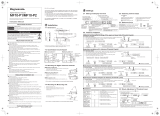
Names and Functions of Parts
<Measuring Head>
1. Power switch : Turns ON and OFF the power.
2. RS-232C terminal : Connect the RS-232C cable when transmitting data back and forth to
the data processor or a PC.
3. AC adapter terminal : Connect the connector plug for the AC Adapter (AC-A17) here when
using the adapter.
4. Measurement button : Press this to measure.
5. Battery chamber cover : Open and close when replacing batteries. When inserting the 4 AAA
size batteries, make sure their polarity orientation is as shown.
6. Light projection tube : The CR-400 light projection tube can be replaced with the optional CR-
A33a, c, d, and f light projection tubes. The CR-410 light projection
tube can be replaced with the optional CR-A33e light projection tube.
7. LCD : Displays measurement data and setting items.
8. Ready lamp : Ready to measure (and fully charged) when green. Always check the
lamp before measuring.
9. Tripod socket : For attaching a tripod to fix the measuring head.
10. Wrist strap attachment : The wrist strap is attached.
RS 232C
DC-IN
5V 2.8A
POWER
*
WARNING : Do not remove covers.
WARNUNG : Niemals das gehäuse öffnen.
(Do not disassemble or modify the instrument.)

16
Names and Functions of Parts
<Measuring Head Key Panel>
1. Calibration key
CAL
• Used when doing a white calibration.
2. Delete/Undo key • Pressing this key while in the measurement screen deletes the latest
data. Pressing again, deleted data comes back. Deleted data is main-
tained until next measurement.
• Moves the cursor forward while pressed in the white calibration screen.
3. key • Moves the cursor in the menu screen.
• Goes back through and displays data in the measurement or color dif-
ference target color screens.
• Adds +1 to the value at the cursor position while in the white calibra-
tion screen.
4. Escape key
ESC
• Used to return to the measurement screen while in the menu screen.
• Used to cancel operations while in the white calibration or color differ-
ence target color screens.
• Returns to normal mode in the PC mode.
• Displays the latest data in the measurement screen.
• Returns to display of selected color difference target color data while in
the color difference target color screen.
5. Color Space key
COLOR
• Changes color space in the measurement screen.
6. Enter key
ENTER
• Pressing this key displays the menu screen while in the start-up screen.
• Changes settings for each item in the menu screen.
• Confirms the selected color difference target color in the color differ-
ence target color screen.
7. Target Color key • Displays the color different target color screen.
• Displays the new color different target color in the color difference
target color screen.

17
<Data Processor>
1. Power switch : Turns ON and OFF the power .
2. RS-232C terminal : Connect the RS-232C cable when transmitting data back and forth to
the data processor or a computer.
3. AC adapter terminal : Connect the connector plug for the AC Adapter (AC-A17) here when
using the adapter.
4.
Roll paper storage chamber
: This is where the roll paper (thermal paper) is stored.
5. Printer : Prints data on the roller paper (thermal paper).
6. LCD : Displays measurement data and setting items.
7. Display contrast : Turning the dial adjusts the contrast of the display to the most appro-
priate level.
8. Battery chamber cover : Open and close when replacing batteries. When inserting the 4 AA size
batteries, make sure their polarity orientation is as shown.
9. Shoulder strap attachment : The optional shoulder strap is attached.
10. Buzzer : Buzzer sounds.

18
Names and Functions of Parts
<Data Processor Key Panel>
Each key sometimes works to activate a function and sometimes simply to input a number or a letter.
[As function keys]
1. Calibration key • Used when doing a white calibration. (only when connected to the
measuring head)
2. Delete/Undo key • Pressing this key while in the measurement screen deletes the latest
data. Pressing again, deleted data comes back. Deleted data is main-
tained until next measurement.
• Deletes or undo a data displayed in the data list.
• Deletes a page while data list is displayed in the page data list.
• Deletes a color difference target color while a color difference target
color list is displayed in the color difference target color.
• Deletes user calibration channels while the calibration channel list is
displayed.
3.
Print/Paper Feed key
• Prints currently displayed measurement results, statistical operation re-
sults, stored data in a data list, or all data in a page.
• Feeds the roll paper when pressed for a long time.
4. Option key
Option
• Displays the option screen (tolerance, automatic measurement, date &
time, import, multi-calibration). (only when connected to the measur-
ing head)
/