Page is loading ...

ISS 506 • Setup Guide
NOTE: For full installation, configuration, and operation details, refer to
the ISS 506 User Guide, available at www.extron.com.
This guide provides quick start instructions for an experienced installer to set up and operate the
Extron ISS 506 Integration Seamless Switchers, a family of seamless, scaling, video and stereo audio switchers.
Installation and Cabling Features
100-240V
50/60 Hz
2A MAX
R/
R-Y
SDI
G/Y
VID
S
B/C
B-Y
H
H/HV
V
H/HV
RS232/422
1
L
R
R/
R-Y
1
2
G/Y
VID
B/C
B-Y
R/
R-Y
G/Y
VID
B/C
B-Y
H/HV
V
H/HV
V
V
R/
R-Y
3
4
G/Y
VID
B/C
B-Y
VID
/Y
R-Y
VID
B-Y
/C
V
G
/Y
5
R
R-Y
RESET
O
U
T
P
U
T
S
6
YC
B/
B-Y
PROGRAM
PREVIEW
RGB/R-Y, Y, B-Y
RGB/R-Y, Y, B-Y
2
L
R
3
L
R
4
L
R
5
L
R
6
L
R
I
N
P
U
T
S
L
R
PREVIEW
FIXED
L
R
PROGRAM
VARIABLE
L
R
LAN
LO-
RES
OUT
R-Y/
R
C
Y/
G
VID
B-Y/
B
Y
Scan Converter
DVI
3G/HD-SDI
3G/HD-SDI
OUT
DVI
OUT
PICTURE
ADJUSTMENTS
CONFIG
DETAIL
ZOOM
BRIGHT/
CONT
COLOR/
TINT
SIZE
POSITION
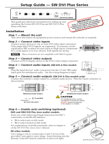
Rear Panel Front Panel
SDI
VID
/Y
5
6
RGB/R-Y, Y, B-Y
PREVIEW
PROGRAM
111 13 12 14
2
5 10 7
3 4 6 8
9
Connections
a
AC power connector
h
Preview Output 15-pin HD connector
(RGB or component)
b
Inputs 1 through 4 configurable BNC connectors
i
Optional Program Output connector(s)
(RGB, component, RGBcvS, S-video, or composite) (DVI, scan converted low resolution, or 3G/HD-SDI
†
)
c
Input 5 configurable BNC connectors
j
Output audio captive screw connectors
(component, S-video, composite)
d
Input 6 configurable mini-DIN and BNC connectors
k
LAN (Ethernet) RJ-45 port
(S-video, composite, SDI/HD-SDI*, auto SDI)
e
Input 1 through 6 audio captive screw connectors
l
RS-232/422 DB-9 port
f
Program Output BNC connectors
m
Reset button
(RGB or component)
g
Program Output 15-pin HD connector
n
Configuration port (front panel)
(RGB or component) (RS-232 only on a 2.5 mm TRS connector)
* An SDI or HD-SDI input is preset only when an optional SDI or HD-SDI input card is installed (DI/DVI, DI/SC, and DI/3G-SDI models).
†
The output for
i
depends on the optional output card installed (DI/DVI, SC, DI/SC, and DI/3G-SDI models).
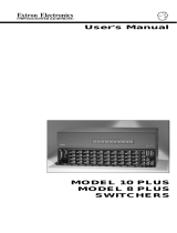
Step 1 — Mounting
Turn off or disconnect all equipment power sources. For tabletop use, affix
the rubber feet. For optional rack mounting, secure the supplied brackets
(see image at right) and mount in a rack.
Step 2 — Video inputs
a. Inputs 1 through 4 — Connect RGB video, component video,
S-video, or composite video to these female BNC connectors.
b. Input 5 — Connect NTSC or PAL component video,
S-video, or composite video to these female BNC
connectors as shown at right.
MBD 249
2U Rack Mount Bracket
(use four lower holes)
RGBHV
Video
Input 1 through 4 Configurations
RGsB or
Component
Video
S-Video
Composite
Video
RGBS or
RGBcvS
Video
H/HV
V
G/Y
VID
H/HV
V
R/
R-Y
R/
R-Y
B/C
B-Y
G/Y
VID
B/C
B-Y
H/HV
V
R/
R-Y
G/Y
VID
B/C
B-Y
H/HV
V
R/
R-Y
G/Y
VID
B/C
B-Y
H/HV
V
R/
R-Y
G/Y
VID
B/C
B-Y
Component Video
VID
/Y
R-Y
B-Y
/C
5
S-Video
VID
/Y
R-Y
B-Y
/C
5
Composite Video
VID
/Y
B-Y
/C
5
R-Y
Input 5 Configurations
ISS 506 • Setup Guide (Continued)

2
c. Input 6 — Connect S-video, composite video or SDI/HD-SDI video
to this female 4-pin mini-DIN or BNC connector as shown at right.
NOTE: The SDI or HD-SDI video input is available only
if the optional SDI input board is installed.
Step 3 — Video outputs
a. Program outputs — Connect video devices to the 15-pin HD output female connector (shown at right) and
the BNC connectors (shown below).
b. If an optional program output board is installed
(see the ISS 506 User Guide, available at
www.extron.com), connect a DVI-D (shown
at right), 3G/HD-SDI (shown below right), or
low resolution device (scan converted output),
shown below, to the board.
c. Preview output — Connect a video device to the 15-pin HD connector.
Step 4 — Audio
a. Connect up to six stereo or mono audio inputs to the 5-pole captive screw input connectors.
b. Connect balanced or unbalanced stereo audio or mono audio devices to one or both of the program captive screw output
connectors and the preview 5-pole captive screw output connector.
NOTE: The Variable Program audio output is adjustable
using the front panel Volume control. The other
audio outputs are not adjustable.
Step 5 — Serial ports
a. If desired, connect a control system or computer to the rear panel RS-232/RS-422 port, as shown below left.
b. If desired, connect a control system or computer to the front panel Configuration (RS-232) port. The optional 9-pin D to 2.5 mm
mini jack TRS RS-232 cable, part number 70-335-01, can be used for this connection, as shown below right.
CONFIG
Sleeve (Gnd)
Ring
Tip
RS-232FunctionPin Function
2
3
5
7
8
TX
RX
Gnd
—
—
Transmit data
Receive data
Signal ground
Not used
Not used
TX–
RX–
Gnd
RX+
TX+
Transmit data (–)
Receive data (–)
Signal ground
Receive data (+)
Transmit data (+)
RS-422
RS232/422
15
69
VID
6
YC
SDI
VID
6
YC
VID
6
YC
SDI
Composite Video SDI or HD-SDI S-Video
SDI
Input 6 Configurations
RGBHV
Video
RGBS
Video
RGsB and
Component
Video
S
H
V
G
/Y
R
R-Y
B/
B-Y
S
H
V
G
/Y
R
R-Y
B/
B-Y
S
H
V
G
/Y
R
R-Y
B/
B-Y
Program Output Configurations
DVI Video
3G/HD-SDI Video
R-Y/
R
C
Y/
G
VID
B-Y/
B
Y
Component Video
S-Video
R-Y/
R
C
Y/
G
VID
B-Y/
B
Y
Composite Video
R-Y/
R
C
Y/
G
VID
B-Y/
B
Y
Scan Converted Output Configurations
NOTE: The ISS outputs S-video and
composite video simultaneously.
Unbalanced Stereo Input
Balanced Stereo Input
Do not tin the wires!
Tip
Ring
Tip
Ring
LR
Sleeves
Tip
Sleeve
Sleeve
Tip
LR
Unbalanced Stereo Output Balanced Stereo Output
Tip
NO GROUND HERE
NO GROUND HERE
Tip
LR
Sleeves
Tip
Ring
Tip
Ring
LR
CAUTION: For unbalanced audio, connect the
sleeves to the ground contact. DO
NOT connect the sleeves to the
negative (-) contacts).
ISS 506 • Setup Guide (Continued)

Step 6 — LAN (Ethernet) port
If desired, connect a network WAN or LAN hub, a control system,
or computer to the Ethernet RJ-45 port. See the ISS 506 User
Guide, available at www.extron.com.
• Network connection — Wire as a patch cable.
• Computer or control system connection — Wire the interface
cable as a crossover cable.
NOTE: Defaults:
• RS-232 • 9600 baud
• IP: 192.168.254.254 • Subnet: 255.255.0.0
• Gateway: 0.0.0.0 • DHCP off
See “Configure Ethernet and RS-232/RS-422 ports,” on
the next page, to change the settings.
Step 7 — Power
AC power connector — Plug in a
standard IEC power cord from a 100 to
240 VAC, 50 - 60 Hz power source into
this receptacle.
Powering Up
Apply power by connecting the power cord to an AC source. The switcher performs a self-test
that displays the model name and the firmware version in the LCD screen. After approximately
2 seconds, the LCD screen reverts to its default display cycle, alternating between three displays:
two showing the selected program and preview inputs and their
rates, and the third showing the selected output rate.
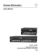
Front Panel Operations
Select an input
Press and release the desired Program or Preview input selection
button. The button lights and the selected input displays on the
program or preview monitor.
Switch the preview output to the program output
NOTE: Select the sub-effect and duration using the Effects
Configuration menu.
1. For an effect to accompany the switch, press one of the Effects buttons.
Wipe — The image in the preview output “unrolls” over the top of the
program output using the duration and sub-effect.
Dissolve — The previous program output fades out and the image from
the preview output fades into the program output using the duration.
PIP — The image in the preview output appears in the program output as
a picture-in-picture window using the duration and sub-effect.
Title — The image in the preview output appears on top of the program
output as a title.
2. Press either the Cut or the Take button.
Cut — If Wipe or Dissolve is selected, the preview output switches to the
program output with no effect.
If PIP or Title is selected, the preview output appears on top of the
program output as a PIP window or title, with no effect.
Take — If Wipe or Dissolve is selected, the preview output switches to the
program output with the effect selected in step 1 and sub-effect and duration.
If PIP is selected, the preview output appears on top of the
program output as a PIP window, with the sub-effect and duration.
If Title is selected, the preview output appears on top of the
program output as a title, with no effect.
A cable wired as T568A at one end
and T568B at the other (Tx and Rx pairs
reversed) is a "crossover" cable.
A cable wired the same at both ends is
called a "straight-through" cable, because
no pin/pair assignments are swapped.
12345678
RJ-45
Connector
Insert Twisted
Pair Wires
Pins:
Crossover Cable
Crossover Cable
Straight-through Cable
Pin
1
2
3
4
5
6
7
8
White-green
Green
White-orange
Blue
White-blue
Orange
White-brown
Brown
T568A T568B
White-orange
Orange
White-green
Blue
White-blue
Green
White-brown
Brown
Pin
1
2
3
4
5
6
7
8
White-orange
White-green
Blue
White-blue
White-brown
Brown
T568BT568B
White-orange
OrangeOrange
White-green
Blue
White-blue
GreenGreen
White-brown
Brown
Wire color Wire color
End 1 End 2 End 1 End 2
Wire color Wire color
2
sec.
2
sec.
2
sec.
Default Display Cycle
10
sec.
Extron
ISS 506 Vn.nn
2
sec.
Integration
SeamlessSwitcher
Power
on
Initializing
Please Wait...
Prog #n {format}
n.nkHz n.nHz
Prev #n {format}
n.nkHz n.nHz
Output Rate
{resolution) @{rate}
ISS 506
Integration Seamless Switcher
VOLUME
ADJUST
ADJUST
TRANSITION
PICTURE
ADJUSTMENTS
CONFIG
PROGRAM
PREVIEW
EFFECTS
MENU
NEXT
DETAIL
ZOOM
BRIGHT/
CONT
COLOR/
TINT
SIZE
POSITION
TAKE
CUT
PIP
TITLE
WIPE
DISSOLVE
LOGO 2
/BLACK
LOGO 1
/BLACK
1 2
3
4
5
6
1
2
3
4
5
6
LOGO 2
/BLACK
LOGO 1
/BLACK
FREEZE
FREEZE
CONFIG
Picture
Adjustments
LCD Volume
Effects
(Wipe/PIP/Dissolve/Title)
Program Bus
(Freeze/Input Selection/Logo)
Transition
(Cut/Take)
Program Bus
(Freeze/Input Selection/Logo)
EFFECTS
Menu Controls
Soft Right
Soft Left
Soft Up
Soft Down
Soft Center In
Soft Center Out
Soft Curtain In
Soft Curtain Out
Soft Square In
Soft Square Out
Soft Plus In
Soft Plus Out
Hard Right
Hard Left
Hard Up
Hard Down
Hard Center In
Hard Center Out
Hard Curtain In
Hard Curtain Out
Hard Square In
Hard Square Out
Hard Plus In
Hard Plus Out
Wipe and PIP sub-effects
ISS 506 • Setup Guide (Continued)

Extron Headquarters
+1.800.633.9876 (Inside USA/Canada Only)
Extron Europe
+31.33.453.4040
Extron Asia
+65.6383.4400
Extron Japan
+81.3.3511.7655
Extron China
+86.21.3760.1568
Extron Middle East
+971.4.2991800
Extron Korea
+82.2.3444.1571
Extron India
+91.80.3055.3777
© 2012 Extron Electronics All rights reserved. www.extron.com
68-1077-50 Rev. B 07 12
Recall and key a saved bitmapped image
NOTE: Bitmap images must first be captured using the
Logo Capture submenu or uploaded via the LAN
port.
1. Press and hold the Next button. Press and release the
desired logo button. Release the Next button.
2. Rotate either Adjust knob to select black screen or a
saved logo. Press the Next button.
3. Rotate the two Adjust knobs to position the logo as
desired on the screen. Press the Next button.
4. Rotate either Adjust knob to select (< >) the desired
method (RGB or level) for keying out (removing) the
unwanted logo material.
5. If you selected RGB as the keying method, rotate the
Adjust
[
knob to select the color plane to key.
6. Rotate the Adjust
{
knob to key out the unwanted
material.
Adjust the Variable Audio output
Rotate the Volume knob to increase or decrease the loudness
or the Variable Audio output.
Recall user presets
NOTE: You must have saved user presets using the menu
system (refer to the ISS 506 User Guide, available at
www.extron.com) before you can recall them.
Repeatedly press and release the input button to cycle
through the saved user presets (up to three) for that input.
Congure Ethernet and RS-232/RS-422 ports
1. Press and hold
Next while you
simultaneously
press Color/Tint,
and Detail to
access the Edit
Comm Settings
submenu.
2. Press Next to page through the submenu.
Serial Port Mode: Rotate the Adjust
[
knob to select the
baud rate and the Adjust
{
knob to select the protocol.
DHCP: Rotate either knob to select (< >) On or Off.
IP Address, Subnet Mask, and Gateway Address: Rotate
the Adjust
[
knob to select (blinking) an octet and the
Adjust
{
knob to change the selected octet.
ISS 506 Control Program
The control program is on the Extron Software Products
DVD. Run the program on a PC connected to either of the
serial ports or the LAN port (see
l
,
n
, or
k
, on page 1). The
program must be installed and cannot be run from the DVD.
NOTE: For details on installing and operating the
program, refer to the ISS 506 User Guide, available
at www.extron.com.
HTML Pages
The HTML pages are built into the switcher and can be
accessed using a Web browser such as Microsoft
®
Internet
Explorer. Enter the IP address of the unit in the Address field
of the browser (192.168.254.254 is the default value).
PICTURE
ADJUSTMENTS
NEXT
DETAIL
ZOOM
BRIGHT/
CONT
COLOR/
TINT
SIZE
MENU
POSITION
ISS 506 • Setup Guide (Continued)
/