Davey ASHS60-08T Operating instructions
- Category
- Sanitary ware
- Type
- Operating instructions
This manual is also suitable for

Installation and
Operating Instructions
Aquashield MAX
Packaged Ultra Violet
Water Treatment System
Incorporating RainBank and Torrium2 Controllers,
Microlene Filters and Sterio Disinfection
Please pass these instructions on to the operator of this equipment.
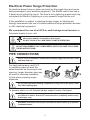
Maximum operating pressure for stainless steel UV chambers is 850kPa (125
psi). If this pressure can be exceeded or if operating close to this pressure t
a suitable pressure limiting valve in the supply to the UV chamber or mains
water line.
Minimum operating pressure is 0kPa. Installation on
a ooded suction is recommended. Installation under
vacuum is not advised, any damage to persons or
associated equipment will not be covered under this
guarantee.
WARNING: The pump, controller & UV Chamber operate under pressure.
Under no circumstances should they be disassembled unless the internal
pressure of the unit has been relieved. Failure to observe this warning will
expose persons to the possibility of personal injury and may result in damage
to the system or other property.
DO NOT DISASSEMBLE ANY COMPONENTS UNTIL YOU HAVE FULLY READ
THESE INSTRUCTIONS!
Ultra Violet radiation is harmful to skin & eyes.
DO NOT LOOK AT UV LAMP WHILE LAMP IS OPERATING.

2
Table of Contents
INTRODUCTION Page 3
PREPARING YOUR SYSTEM Page 4
Choosing a Site Page 5
Power Connection Page 5
Pipe Connections Page 6
PUMP CONTROLLERS – Torrium2 Page 7
– RainBank Page 9
PRE-TREATMENT – (FILTRATION) Page 12
Sterio – (DISINFECTION) Page 13
Lamp Installation Page 14
Operation Page 15
Maintenance Page 15
Water Quality Page 16
Lamp Alarm System Page 17
TROUBLE SHOOTING Page 18

3
INTRODUCTION
Congratulations on your purchase of a high quality, award winning
Aquashield
MAX Ultra Violet water treatment system.
Aquashield
MAX represents advances in safety and convenience of
rainwater harvesting technology for rainwater users. The range offers
increased water treatment quality and safety - producing water that is
biologically safe to drink, without the use of chemicals.
This all in one unit is pre tted with a correctly matched pump, Microlene
cartridges and housings and Sterio units and can come with either the
Rainbank or the Torrium2 pump controller.
Applications: Pressure boosting and disinfection of rainwater for:
• School shower and toilet blocks
• Commercial toilet ushing
• Large home potable water supply
• Industry process water treatment
• Guest house potable water supply
• Bacteria and algae growth control for aquaculture and water features
• Also suitable for bore and surface water treatment – *subject to a water
quality test
Features & Benets:
• Factory matched and tested package – ensures correct UV dosage and
high reliability
• Pump interlock detects lamp failure and locks pump out– ensures only
disinfected water is delivered
• Lamp count down timer with set limit of 9000 hours - ensures only
disinfected water is delivered
• Durable UV resistant cover – allows for exible, vandal resistant exterior
installation
• RainBank controller options – provides seamless automatic mains water
backup
• Torrium2 controller options – intelligent automatic pump control
maximizes pump efciency by adjusting run on time and cut in pressures
• 2 x 20” Jumbo cartridge lter housings – for low friction losses and long
cleaning intervals
• 20 micron ltration – for long cleaning intervals and dirt, rust, sediment
and debris reduction
• 1 micron ltration – for parasitic cyst reduction and high UV dosage rates

4
PREPARING YOUR SYSTEM
Your new Aquashield
MAX system incorporates a lamp failure system
design feature that enables you to be warned of a lamp failure by :-
1. A lamp failure LED
2. An audible alarm
3. Remote alarm contacts
4. Pump lock out feature
In addition when the alarm “beeps” on and off, the lamp is due to be
changed so effective treatment is maintained.
Aquashield
®
MAX
with RainBank
®
Aquashield
®
MAX
with Torrium
®
2
Before installing your new Aquashield
MAX please read all instructions
carefully as failures caused by incorrect installation or operation are not
covered by the guarantee. Your Ultra Violet water treatment system is
designed to handle clean water. The system should not be used for any other
purpose without specic referral to Davey Water Products. The use of the
system with ammable, corrosive and other materials of a hazardous nature
is specically excluded.
DO NOT DISASSEMBLE ANY COMPONENTS UNTIL YOU HAVE FULLY READ
THESE INSTRUCTIONS!
Torrium2
Controller
HM or
HS Pump
Steriflo
UV Lamp
Steriflo Lamp
Controller &
Power Pack
RainBank
Controller
HM or
HS Pump
Steriflo
UV Lamp
Steriflo Lamp
Controller &
Power Pack

5
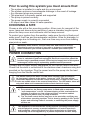
Prior to using this system you must ensure that:
• The system is installed in a safe and dry environment
• The system enclosure has adequate drainage in the event of leakage
• Any transport plugs are removed
• The pipe-work is correctly sealed and supported
• The pump is primed correctly
• The power supply is correctly connected
• All steps have been taken for safe operation
CHOOSING A SITE
Choose a site with a rm mounting position. Allow room for removal of the
cover, lamp and sleeve during servicing. Leave a chamber lengths space
above the lamp cover and connector end for lamp removal.
To protect your system from the weather, make sure the site is ood proof,
water proof, frost free and has adequate ventilation. Allow for drainage, to
avoid damage due to ooding etc., that over time may occur from leaking
pipe joints or seals.
POWER CONNECTION
Connect lead to power supply designated on the Sterio control box label.
Check that the earth is connected to the stainless steel chambers using bolt
provided on the chamber. Plug the power lead for the pump into the lead
hanging from the Sterio control box.
WARNING: Some insects, such as small ants, nd electrical devices
attractive for various reasons. If your site or enclosure is susceptible to
insect infestation you should implement a suitable pest control plan.
WARNING: When servicing or attending your Aquashield
MAX, always ensure
power is switched off and lead unplugged. Electrical connections should be
serviced only by qualied persons. If the electrical supply lead of this system
is damaged, it must only be replaced by qualied service personnel.
The Sterio control box has a red LED alarm indicator light mounted on
its front panel, adjacent to the amber “power on” LED. This light will be
illuminated whenever the Sterio control box senses no lamp current. There
is also an audible alarm in the event of lamp failure. The LED and/or alarm will
only work when unit is connected to the correct electrical supply.
NOTE:
a) For protection, the Davey pump motor is tted with an automatic
“over temperature” cut-out. Constant tripping of this overload device
indicates a problem e.g. low voltage at pump, excessive ambient
temperature (above 50°C) in pump enclosure.
b) The Torrium2 control device may have to be reset after rectifying any
of the above operating troubles. This is done by pushing in the “prime”
button and releasing it after 2 seconds, or switching the power supply
off then on.
This appliance is not intended for use by persons (including children) with
reduced physical, sensory or mental capabilities, or lack of experience
and knowledge, unless they have been given supervision or instruction
concerning use of the appliance by a person responsible for their safety.

6
Electrical Power Surge Protection
An electrical power surge or spike can travel on the supply lines and cause
serious damage to your electrical equipment. The Sterio control box has a
2 Amp fuse to protect the circuit. The fuse is not a lightning arrestor and may
not protect the Sterio if lightning or a very powerful surge hits the unit.
If the installation is subject to electrical power surges or lightning we
strongly recommend the use of suitable additional surge protection devices
on ALL electrical equipment.
We recommend the use of an RCD or earth leakage circuit breaker on
the power supply to your unit.
Ultra violet radiation is harmful to skin & eyes.
DO NOT LOOK AT UV LAMP WHILE LAMP IS OPERATING.
DO NOT DISASSEMBLE ANY COMPONENTS UNTIL YOU HAVE FULLY READ
THESE INSTRUCTIONS!
PIPE CONNECTIONS
NOTE: Prior to installation remove the transport plugs from the inlet, outlet
and lamp end cap.
For best performance use P.V.C.
or polythene pipes at least the
same diameter as the pump’s inlet
opening. Larger diameter pipe may
be used to minimise resistance
to ow when pumping longer
distances.
Do not use pipe thread sealing compounds on any part of this pump. ONLY
use Teon sealing tape.
To prevent strain on unit threads always support heavy inlet pipes.
NOTE: Suction leaks are the largest cause of poor pump performance and
are difcult to detect. Ensure all connections are completely sealed using
thread tape only.
RainBank controllers can only be connected to mains water, by a qualied
licensed plumber.

7
PUMP CONTROLLERS
Option 1 – Torrium2
Your new system incorporates ‘Torrium2’, electronic ow controller – a
Davey designed unit that enables the use of a highly efcient pump design
and offers the following benets:–
1. Enables the pump to deliver a constant ow of water particularly at
low ow rates – reducing the inconvenience of pressure variation in
showers etc.
2. Provides automatic “cut-out” protection should the pump run out of
water or overheat*.
3. Provides warning indications for critical and noncritical system faults.
4. Has adaptive pressure cut-in which allows the pump to start at
approximately 80% of the maximum pressure at last shut-down.
This allows the controller to accommodate varying inlet pressures and
pump performance.
5. Automatic retry functions in the event of a critical system fault.
* Motor overload / overheat protection included. Motor has its own overload
/ overheat protection.
The Davey Torrium2 tted to this pump has a status indicator light mounted
on its front panel. This light will be illuminated whenever the Torrium2
senses that there is electrical power available. The light will only work
when unit is connected to the correct electrical supply.
The electrical connections and checks must be made by a qualied
electrician and comply with applicable local standards.
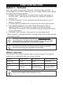
Status Indicator
The Torrium2 has a status indicator light on the front panel. This light will
enable you to understand what your pump is doing.
Condition Indicator readout Pump operation Restart / Reset Method
Standby mode Red light Standby Pressure drop
Running Green light Running N/A
Fault Yellow light
Stops, auto-retry &
‘water return’ activated
Push ‘Prime’ button or
cycle power off / on
Only one fault condition will be indicated at once.

8
Auto-retry and Water Return Modes
Should your Torrium2 detect a loss of prime, after stopping the pump, it
will wait ve minutes before activating Auto-retry and Water Return modes.
Auto-retry automatically starts the pump to see if the pump is now primed. It
does this after 5 mins, 30 mins, 1 hr, 2 hrs, 8 hrs, 16 hrs and 32 hrs. Water
return mode will restart the pump automatically if the Torrium2 detects water
ow through it.
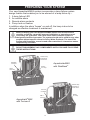
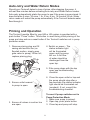
Priming and Operation
The Torrium2 module tted to your HM or HS system is provided with a
push button “Prime” button. This button is used during initial priming of the
pump and also acts as a reset button if the Torrium2 switches out in pump
protection mode.
1. Remove priming plug and ll
casing and suction line (on
ooded suction, simply open
gate valve to pump). When full,
replace priming plug.
2. Ensure outlet nearest
to pump is open.
3. Ensure all valves in suction line
are open.
4. Switch on power - The
status indicator light
will be illuminated
green and the pump
will run. A full ow
of water should be
discharged from the
open tap.
5. If the pump stops with the tap
open see troubleshooting
checklist.
6. Close the open outlet or tap and
the pump should stop after a
few seconds (the status indicator
light should be illuminated red
(constant). If not, consult the
troubleshooting checklist.
To reset if pump switches out in
Pump Protection Mode
1. Make sure pump is primed.
2. Open tap, push prime button.
3. Close tap and pump will stop.

9
Option 2 – RainBank – HOW IT WORKS
1. When there is demand for water from your toilet, washing machine or
garden tap RainBank senses this demand and checks the level of water
in the rainwater tank. Note: demand must be greater than 1.5 litres per
minute or mains water will be delivered.
2. If there is rainwater in the tank RainBank
switches on the pump. The
pressure of the pump is sufcient to overcome the pressure of the mains
water inside RainBank and this closes a dual check valve and allows the
rainwater to ow.
3. When there is no longer a demand for water, RainBank detects that
water has ceased to move inside the pipes, switches off the pump and
waits for another water demand.
4. If RainBank senses a water demand and detects insufcient water in the
rainwater tank it will automatically allow the mains water to ow.
5. If there is a power failure during a demand for water RainBank will
automatically supply the mains water as backup.

10
100
100
100
100
C
D
E
F
A
D
E
B
A
D
E
B
100
100
100
100
C
D
E
F
A
D
E
B
A
D
E
B
100
100
100
100
C
D
E
F
A
D
E
B
A
D
E
B
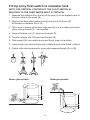
Underground tankAbove ground tank
Fit top entry oat switch to rainwater tank
NOTE: THE VERTICAL POSITION OF THE FLOAT SWITCH IN
RELATION TO THE PUMP WATER INLET IS CRITIaCAL
1. Measure the distance from the top of the tank (A) to the highest point of
the tank outlet to the pump (B).
2. Mark on the oat switch cable a length equal to A-B minus 200
millimeters or distance (B) to (D).
3. Drill a hole in the top of the tank large enough to suit a cable grommet or
strain relief grommet (F) - not supplied.
4. Snap off retainer clip (C) from top of weight (D).
5. Position retainer clip 100mm from oat ball (E).
6. Slide weight (E) over retaining clip and rmly snap into position.
7. Lower weight into tank and feed top of cable through hole drilled in Step 3.
8. Fasten with cable grommet to previously measured length (A) to (B).

11
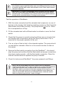
Test the operation of RainBank
®
.
1. With the mains connected and the rainwater tank empty turn on one of
the taps in the laundry that feeds the washing machine or ush the toilet.
Mains water should ow normally. The pump should not turn on. When
this is completed turn off tap.
2. Fill the rainwater tank with sufcient water to activate or cover the oat
switch.
3. Check that the pump is correctly primed and there are no air locks that
will interfere with its operation as per the Davey instructions. This is
essential for the proper operation of the unit.
4. Turn on a tap or ush a toilet in the rainwater system. The pump should
run and deliver rainwater. Allow to run for several minutes to clear air
from pipes.
5. Remove the oat switch connection from the RainBank
®
– this should
stop the pump and conrms that the oat switch and power connections
have been made correctly - ret the oat switch connection. Press the
manual override button to operate the pump if needed.
6. Check for leaks around RainBank
®
, the pump, pipework and ttings.
IMPORTANT: To allow easy connection it is strongly recommended that you
have exible copper pipes that allow some movement so that they can line
up exactly with the mains water and rainwater outlet. These pipes must be
3 ⁄4 inch in diameter.
IMPORTANT: It is highly recommended that an isolation valve be tted to
where the mains water enters RainBank
®
and between the pump and the
rainwater tank. This facilitates easy removal of the unit if required without
turning off the household water or losing stored rainwater.
NOTE: Do not install additional suction check valves on RainBank
®
systems except where a foot valve is required (eg. suction lift installations).
In the case of suction lifts, to allow for the correct operation of your
RainBank
®
and for movement of the tank and pump which may occur over
time, the suction pipe must have a length of exible suction hose from
pump to top of tank. This hose can be braided hose, reinforced suction
hose or polythene pipe at least 1 metre in length.

12
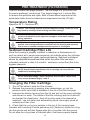
PRE-TREATMENT (FILTRATION)
This unit includes two-stage ltration. The rst stage is a 20 micron lter
to remove sediment, rust and grit. The second stage is a 1 micron lter
to remove ne particles and cysts. Both of these lters help ensure that
particulate matter does not shield micro-organisms from the UV light.
Temperature Rating
Maximum 50
o
C - Minimum 8
o
C
Sediment Cartridge Filter Life
Once the housing is properly installed, a reduction in ow/pressure (to
such an extent as to cause inconvenience) will indicate when the cartridge
is becoming clogged and needs replacing/cleaning. Sediment cartridges
should be replaced/cleaned/sanitised when the water ow has been
noticeably reduced or after 3-6 months - whichever comes rst (this is for
hygiene reasons).
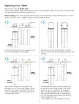
Changing the Filter Cartridge
1. Turn off the valve to stop the ow of water.
2. Release the pressure by opening a tap downstream, or use the
pressure relief valve that is available in the lid of the lter housings.
3. Unscrew the bottom housing from the lid and pull out the used cartridge
and discard or wash. The inside of the lter housing and the lid should
be checked for cleanliness - they will usually need to be cleaned or
sanitised - use hot water and dishwashing liquid, thoroughly scrub all
surfaces and then rinse.
4. Check that the o-ring is in position in the top of the housing base,
lubricate with a coating of white petroleum jelly (Vaseline), place the o-ring
into the groove and with two ngers wipe the o-ring down into the groove.
Do not wipe the o-ring clean of lubricant after it has been properly seated
Caution: The housing must be protected against freezing. Failure to do so
may result in cracking of the housing and water leakage.
NOTE: Actual ltration/purication life of cartridge can vary with the
condition of incoming water.
NOTE: Clean lter Stage 1 once a pressure drop of 100 to 150kPa from
clean occurs between Stages 1 and 2.
WARNING: CAREFULLY AND GENTLY TIGHTEN WITH HOUSING SPANNER
as the bowl should only be tightened enough to avoid water leaking
during operation.
WARNING: If the water system is not going to be used for extended
periods, the cartridge should be removed from the housing and replaced
with a new or cleaned cartridge when the system is used again.

13
IMPORTANT: When opening the lter housing to install or change the
cartridge (element) it is common for the o-ring seaI to lift out of the groove
and, at times, it may even stick to the cap.
CAUTION WHEN INSTALLING
1. This is a plastic product with a female thread. If you cross-thread a
male tting, and/or you over pack with sealing tape, you could do
permanent damage.
2. If you use a tapered thread male tting do not over tighten.
3. No warranty claims will be considered for damage due to incorrect
installation.
in the groove because the lubricant prevents “crawling” of the o-ring
during the tightening of the lid and thus prevents water leaks.
5. Screw the housing onto the lid and hand tighten. Open the tap
downstream of the lter and then open the inlet valve.
Sterio
Your new Sterio system incorporates a lamp failure system design feature
that enables you to be warned of a lamp failure by :-
1. A lamp failure LED
2. An audible alarm
3. Remote alarm contacts
In addition when the alarm “beeps” on and off, the lamp is due to be
changed so that effective treatment is maintained.
Lamp Lead
1 metre
Power Lead to Outlet
1.5 metr
e
Alarm LED (Red)
Alarm reset
On LED (Amber)
Lead to Power Pump (use is optional)
0.65 metre
Outlet 20mm BSP(F) - internal
25mm BSP(M) - external
Quartz Sleeve
TT600
UV Lamp
GPH550N2W
Inlet

14
Connect lead to power supply designated on control box label. Check that
the earth is connected to the stainless steel chambers using bolt provided
on the chamber.
CAUTION: The supply cord is necessary for lamp changing. The three pin
supply plug must remain accessible after installation. If installed to xed
wiring without the plug a two pole switch must be tted and its ON and OFF
positions shall be marked.
The Sterio control box has a red LED alarm indicator light mounted on
its front panel, adjacent to the amber “power on” LED. This light will be
illuminated whenever the Sterio control box senses no lamp current. There
is also an audible alarm in the event of lamp failure. The LED and/or alarm will
only work when unit is connected to the correct electrical supply.
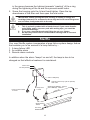
BSP Nipple
Earth Stud
S334A (Aluminium)
Quartz Sleeve
TT600
O-ring S24x3N70
Pressure Ring
S113
M3 Screws x 2
Lamp Connector
Earth Lug
Lock Washer
M6
Nut
Short Open Endcap
S333A
UV Lamp
GPH550N2/W
LAMP INSTALLATION
The Quartz Sleeve is pre-installed in the treatment chamber, and provided
the endcap has not been disturbed or undone, is able to withstand well in
excess of the maximum operating pressures.
Expose the connection end of the lamp from its transport tube and
protective wrapping. The lamp connection socket is “keyed” to ensure
correct alignment. Carefully remove the tube fully from its transport tube,
touching the lamp as little as possible. Handle the lamp by the ends where
possible. Wipe with clean cloth and methylated spirits if ngerprints or dirt
need removing.
Slide the lamp into the chamber, t lamp connection socket and then fasten
the end washer into the endcap, with the screws provided.

15
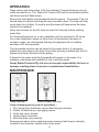
OPERATION
Open valves and allow water to ll the chamber. Connect three pin plug to
outlet and switch on. The “Mains On” Amber LED will be illuminated and the
red alarm light will ash slowly.
Ensure the reset button is pressed and held for approx. 10 seconds. The unit
should beep to indicate the lamp life timer has been reset. The timer will then
count down for a further 12 months and the alarm will beep when the lamp
needs to be replaced.
Allow two minutes for the UV lamp to reach full intensity before starting
water ow.
Full lamp performance for a new installation will be achieved in 24 hours.
On a new installation where no other form of sterilisation has been in
constant usage, we recommend ushing the pipework with a suitable
sanitiser such as Acquasafe.
The Acquasafe solution can be dosed to the water tank or if necessary
added as a shot dose to the bowl of any lter housing installed with the UV
system and slowly ushed into the piping.
If dosed to the water tank the Acquasafe will remain in the water. It is
tasteless, odourless and suitable for use in drinking water.
Davey Water Products Pty Ltd can not accept responsibility for loss or
damage resulting from incorrect or unauthorised installations.
MAINTENANCE
Lamp removal Quartz sleeve removal
Lamp changing (every year of operation) :
1. Shut valve(s) so that water cannot ow through steriliser.
2. Switch off steriliser by unplugging mains.
3. Undo end cover screws.
4. Unplug lamp connector.
5. Remove lamp very carefully.
Reverse procedure when replacing lamp, ensuring that lamp is centrally
located in the chamber. Handle only by the ends.

16
Quartz Sleeve Cleaning :
If dirt is allowed to build up on the quartz sleeve it will impair the UV output.
The quartz sleeve should be removed after one month and inspected for
deposits. Clean with calcium lime and rust remover (CLR). Apply some CLR
to a soft cloth and wipe the quartz sleeve. Once clean, wipe any residual
CLR off with a wet soft cloth. Handle the sleeve with tissue to keep it clean.
The sleeve should be cleaned every three months or as required.
Sleeve removal (use care-fragile) :
CAUTION: Handling lamp and quartz sleeve. Keep the quartz components
free of nger marks to avoid loss of output through dirt or grease shadows
- handle the lamps by their ends where possible. Wipe lamp and sleeve with
clean cloth or tissue if needed. The o-rings should be replaced annually or if
damaged – do not grease the o-rings.
1. Remove lamp as described.
2. Remove drain port cap and empty water from chamber.
3. Undo nut at top of the chamber and remove o-ring, withdraw sleeve
carefully. A thin piece of dowel can be used to assist.
NOTE: When withdrawing sleeve take care not to let the end drop into the
chamber as it could break.
4. Inspect o-rings for damage, replace annually.
Reverse procedure when replacing sleeve.
When replacing quartz sleeve after cleaning, the sleeve should stick out
about 1cm at the top. Place o-ring over closed nut end and t closed nut,
fastening it hand tight.
A tiny amount of silicon spray or CRC in the end of aluminium endcap
threads will aid easy tightening. Do not use excessive force when tightening
nuts. Do not re-use quartz sleeve or o-rings if damaged.
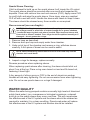
WATER QUALITY
Where the water being pumped contains unusually high levels of dissolved
solids (hard water), iron, manganese or biological organisms, a deposit
build up on the quartz sleeve may occur over time. This will compromise
the effectiveness of the UV system and the sleeve should be cleaned as
required to maintain it in a clean condition. Discoloured water will reduce
the effectiveness of the UV system and ltration should be installed.

17
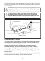
LAMP ALARM SYSTEM
If the UV lamp is out due to a failure or bad connection the alarm buzzer will
sound and the red LED will light. The alarm will disconnect power from the
pump preventing untreated water from being delivered. The alarm function
can be checked by switching the unit off, disconnecting the lamp and then
switching the unit back on.
The lamp should be replaced after a year’s running time. The alarm will
beep intermittently after the internal clock has measured this time as a
reminder to change the lamp. Pressing the recessed ‘reset’ button with a
ballpoint pen will silence it for 24 hours at a time to allow time for a new
lamp to be obtained. Once a new lamp is installed press the reset button for
5 seconds to start another year’s timing. Do this whenever a new lamp is
installed. The alarm light ashes slowly during normal operation to show the
timer circuit is running.
If alarm sounds when new lamp is inserted, turn power off for ve minutes
to allow for internal reset of the power supply.

18
TROUBLESHOOTING
Torrium2
a) PUMP HAS STOPPED OR MOTOR RUNS FOR SHORT PERIOD
ONLY WHEN SWITCHED ON OR PRIME BUTTON PUSHED, BUT
DOES NOT PUMP.
1. Suction line and pump body not lled with water.
2. Air leaks in suction lines or suction pipe not under water.
3. Air trapped in suction lines (also possible with ooded suction due to
uneven rise in piping; eliminate humps and hollows).
4. No water at source or water level too low.
5. Valve on suction lines closed. Open valve & pump will restart
automatically or press “Prime” button.
b) PUMP SWITCHES ON AND OFF FREQUENTLY (CYCLING)
1. Cycling may occasionally be caused by oat valves lling tanks.
2. Leaking taps, oat valves etc. check plumbing.
3. Leaking check valve/foot valve.
4. Discharge plumbing has been connected to the priming port.
c) MOTOR DOESN’T START WHEN SWITCHED ON - LOW PRESSURE
INDICATOR LIGHT NOT ILLUMINATED
1. Power not connected or no power available from supply outlet.
WARNING: Automatic reset thermal overloads may allow the pump to restart
without warning. Always disconnect the pump motor from the electrical supply
before maintenance or repairs.
WARNING: When servicing or attending pump and/or controllers, always
ensure power is switched off and lead unplugged. Electrical connections
should be serviced only by qualied persons.
d) PUMP WILL NOT STOP
1. Water leaks on discharge side of pump.
RainBank
a) PUMP WILL NOT SWITCH OFF
1. Yellow ‘manual override’ button pushed in too far. Pry out the section
of the yellow button that has been pushed into the RainBank housing
with a small at blade screwdriver.
2. Water is still being used. Check all taps, toilets and appliances
connected to RainBank system to ensure they are turned off.
3. Water is leaking on discharge side of RainBank system.
4. Rock or debris caught inside RainBank. Call your plumber to t a Y
strainer - RainBank will need to be returned to Davey.

19
b) PUMP WILL NOT SWITCH ON
1. Pump not plugged in. Plug pump into base of RainBank and
RainBank into power supply.
2. No power supply to pump. Contact electrician and have power
restored.
3. Float switch not connected to RainBank. Plug oat lead into base
of RainBank. The connection port is located next to the power lead
coming from the RainBank. To conrm the connection is correct,
depress yellow button, pump will start.
4. No water in tank. Check water level in tank.
5. Float switch located at water tank is installed incorrectly.
6. Mains water supply not connected to RainBank. RainBank system
must have a pressurised water supply connected to inlet. Press
yellow “manual override” button to simulate mains water owing.
7. Mains supply to RainBank turned off. Turn on mains water supply.
8. Pump is faulty. To conrm if the fault is within the pump, plug the
pump directly into power point and check to see if it starts. If the
pump starts plug the pump back into the RainBank
®
and continue
fault nding. If the pump does not start contact your supplier for
further advice.
9. Lead from oat switch to pump broken or damaged. Replace oat
and lead assembly.
10. Float switch defective. Contact your supplier for further advice.
11. Check power to the Sterio control box. Lamp may need to be
replaced – required yearly.
c) OTHER SYMPTOMS
Mains water is still in use when pump is running.
Possible cause - pump needs to be primed. Remove priming plug from
front top of pump (right above water inlet) and allow all air to escape
from pump. Replace the priming plug when water dribbles out of hole.
Mains water is still in use when pump is running.
Possible cause - pump impeller blocked. Have pump serviced. Fit rst
ush devices and Y strainer to pipework.
Mains water not passing through RainBank.
Possible cause - debris is blocking inlet to RainBank. Remove RainBank
and clean inlet.
Pump hums.
Possible cause - pump is jammed or seized. Have pump serviced.

20
Sterio
Principle. A ballast (choke) provides the correct voltage and current for the
lamp(s). The circuit board monitors the current to the lamp and if it is not
present, illuminates the red alarm light and sounds the alarm buzzer (a
“squealing” noise). An orange light indicates the power is on.
a) UV LAMP OUT, NO ORANGE “ON” LIGHT, NO ALARM
1. No mains voltage.
2. Internal fuse failed.
3. Check mains power connections inside power supply.
b) UV LAMP FLICKERING, ALARM ON
1. Failed lamp.
2. Incorrect lamp or ballast tted.
c) UV LAMP OUT, ALARM ON
1. Lamp failed.
2. Poor connection to lamp (check/clean connector/lamp pins).
3. Ballast failed (unlikely).
d) LAMP ON, ALARM ON
1. Faulty circuit board.
e) LAMP OUT, ALARM OFF
1. Loose connection or faulty circuit board, possibly short in lamp circuit.
Part Numbers
a) Lamp
GPH550N2/W
b) Sleeve
TT600
c) O-rings
All models S24x3N70 (2 per sleeve)
WARNING: When servicing or attending your Sterio, always ensure power is
switched off and lead unplugged. Electrical connections should be serviced
only by qualied persons. If the supply cord is damaged, it must be replaced
by the manufacturer, its service agent or similarly qualied persons in order
to avoid a hazard.
Care should also be taken when servicing or disassembling the unit and
associated pipework to avoid possible injury from pressurised water. Unplug
power, relieve pressure by opening a tap on the discharge side of the unit and
allow any water in the unit to cool before attempting to dismantle.
Page is loading ...
Page is loading ...
Page is loading ...
Page is loading ...
-
 1
1
-
 2
2
-
 3
3
-
 4
4
-
 5
5
-
 6
6
-
 7
7
-
 8
8
-
 9
9
-
 10
10
-
 11
11
-
 12
12
-
 13
13
-
 14
14
-
 15
15
-
 16
16
-
 17
17
-
 18
18
-
 19
19
-
 20
20
-
 21
21
-
 22
22
-
 23
23
-
 24
24


Davey ASHS60-08T Operating instructions
- Category
- Sanitary ware
- Type
- Operating instructions
- This manual is also suitable for
Ask a question and I''ll find the answer in the document
Finding information in a document is now easier with AI
Related papers
-
Davey eVo2 Operating instructions
-
Davey Water Products Steriflo UV50 Operating instructions
-
-
Davey HS60-08T Operating instructions
-
-
Davey 25301 Operating instructions
-
-
-
-
Other documents
-
 PRO+AQUA FC-PK-100E User manual
-
Viqua 602810-102 User manual
-
Philips AIB6320/93 User manual
-
US Water Sterilight Ultraviolet System User manual
-
Pelican Water PUV-16-Lamp Installation guide
-
 PRO+AQUA PRO-100-E Operating instructions
-
3P Technik 1000500 Installation guide
-
 Aquawise Aquapro Installation And Maintenance Booklet
-
 Bio Energiser D-tox Spa Classic Owner's manual
-
vitapur VPS1140 Operating instructions


