
We’re here to help 866-558-5706
Hrs: M-F 9am to 5pm EST
IS-8T-US
1
2
3
4
5
6
1
2
3
4
5
6
1
2
3
4
5
6
1
2
3
4
5
6
1
2
3
4
5
6
1
2
3
4
5
6
Best Practices...
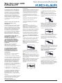
With a copper weight that extends the
tape run length and installer friendly
features of a push in connector system
with universal polarity, Kichler® 8T
tape light offers commercial grade
24/7 operation. Pair with our plug-
and-play power supplies, connectors
and extruded channels for numerous
applications.
Installation Instructions
For Use in Dry Locations Only
All installations should comply with
national and local electrical codes. If you
have any doubts concerning installation,
contact a qualied, licensed electrician.
Supply leads and Accessories are
not listed for In Wall use. Read all
instructions thoroughly before starting
installation.
• This xture can only be used with
Kichler® Class 2, 24V DC power
supplies and accessories.
• Standard output (8T1xxxSxxxx) tape
is “Suitable for installation in the
storage area of a clothes closet” in
US only.
• Note: High (8T1xxxHxxxx) and Ultra
High (8T1xxxUxxxx) output tape is not
rated for use in a clothes closet.
• Voltage drop limits the linear run
length of 24V DC xtures, and these
lengths differ between the products
listed below.
a.8T1xxxSxxxx = 67 feet (Standard)
b.8T1xxxHxxxx = 33 feet (High)
c.8T1xxxUxxxx = 10 feet (Ultra High)
• Total wattage of tape light should
not exceed power supply wattage. To
determine the total wattage of tape light,
multiply the total number of feet used
by the wattages listed below for the
appropriate tape light type.
a. 8T1xxxSxxxx = 1.5 W/ft. (Standard)
b. 8T1xxxHxxxx = 3 W/ft. (High)
c. 8T1xxUxxxx = 7.2 W/ft. (Ultra High)
* Maximum linear run length is
determined using a 96W power supply &
a 1’ power supply lead with a continuous
linear run of LED tape light.
Please contact Kichler’s Advanced
Technical Support team for questions
about the maximum run length at
techsupport@kichler.com
Pre Installation Checklist
• Prepare the location that the LED tape
light will be installed. Make sure that the
area has been thoroughly cleaned and is
dry. If installing underneath a cabinet, it is
recommended to install tape light at least
1-1/2” away from cabinet lip to prevent
shadowing on counter top surface.
• Determine location for power supply and
length of supply lead wire that will be needed.
• Determine how many sections of tape light
and Accessories that will be needed.
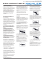
Installation
1. Install power supply.
Note: The power supply should be installed
by a qualied electrician and be installed in
accordance with national and local electric
codes. Refer to the power supply installation
instructions for further detail.
2. Run supply lead wire from power supply to
beginning of tape light run. Do not connect
lead wire to power supply yet.
3. Measure and if necessary, cut the rst
section of tape light, leaving a minimum
of one inch of space on each end for
connections.
Note: To cut the tape light, use a pair of
sharp scissors or snips and cut on the dotted
cut line only.
4. Connect tape light to supply lead wire
using a Tape-to-Wire Accessory (8T1TWxx)
or direct solder connection.
Note: Make sure +/- symbols on the
Accessory or tape light solder locations line
up with the +/- symbols of the supply lead
wire.
Note: The Tape-to-Wire Accessory will
accept 20-22AWG wire. Strip wire to .15”. If
necessary, twist and pull to extract wire no
more than 3 times per accessory.
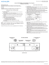
To Connect
1. Gently remove the pin protector from any
Accessory in line.
2. Press the Accessory connector into the
desired Tape Light connector.
Note: The Accessory is designed such that
polarity will always be maintained, regardless
of the orientation of the Accessory to the
Tape Light.
Note: An Accessory can be disconnected
from the Tape Light by holding down the
tape light (away from the LEDs and other
components) and pulling the Accessory
directly away from the Tape Light. To
prevent damage, do not attempt more than 3
connection cycles.
3. Remove 3M backing from tape light and
apply making sure to press between the
LED’s and other components. Pressing on
the LED’s and other components will result in
damage to the tape.
Note: For best results, peel off backing and
apply tape light in small sections starting at
the beginning of the run.
Note: Avoid using excessive force to
prevent damage to LEDs and other
components.
4. Install any additional sections of tape light
and connectors in the same manner.
5. Connect power supply lead to power
supply and turn on.
Note: Before powering on the system,
double check that the supply lead and any
subsequent wired connections have polarity
(+/-) symbols that are oriented in the same
direction.
8T LED Tape Light
Page is loading ...

We’re here to help 866-558-5706
Hrs: M-F 9am to 5pm EST
IS-8T-CB
1
2
3
4
5
6
1
2
3
4
5
6
1
2
3
4
5
6
1
2
3
4
5
6
1
2
3
4
5
6
1
2
3
4
5
6
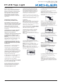
Best Practices...
With a copper weight that extends the
tape run length and installer friendly
features of a push in connector system
with universal polarity, Kichler® 8T
tape light offers commercial grade
24/7 operation. Pair with our plug-
and-play power supplies, connectors
and extruded channels for numerous
applications.
Installation Instructions
For Use in Dry Locations Only
All installations should comply with
national and local electrical codes. If you
have any doubts concerning installation,
contact a qualied, licensed electrician.
Supply leads and Accessories are
not listed for In Wall use. Read all
instructions thoroughly before starting
installation.
• This xture can only be used with
Kichler® Class 2, 24V DC power
supplies and accessories.
• Standard output (8T1xxxSxxxx) tape
is “Suitable for installation in the
storage area of a clothes closet” in
US only.
• Note: High (8T1xxxHxxxx) and Ultra
High (8T1xxxUxxxx) output tape is not
rated for use in a clothes closet.
• Voltage drop limits the linear run
length of 24V DC xtures, and these
lengths differ between the products
listed below.
a.8T1xxxSxxxx = 67 feet (Standard)
b.8T1xxxHxxxx = 33 feet (High)
c.8T1xxxUxxxx = 10 feet (Ultra High)
• Total wattage of tape light should
not exceed power supply wattage. To
determine the total wattage of tape light,
multiply the total number of feet used
by the wattages listed below for the
appropriate tape light type.
a. 8T1xxxSxxxx = 1.5 W/ft. (Standard)
b. 8T1xxxHxxxx = 3 W/ft. (High)
c. 8T1xxUxxxx = 7.2 W/ft. (Ultra High)
* Maximum linear run length is
determined using a 96W power supply &
a 1’ power supply lead with a continuous
linear run of LED tape light.
Please contact Kichler’s Advanced
Technical Support team for questions
about the maximum run length at
techsupport@kichler.com
Pre Installation Checklist
• Prepare the location that the LED tape
light will be installed. Make sure that the
area has been thoroughly cleaned and is
dry. If installing underneath a cabinet, it is
recommended to install tape light at least
1-1/2” away from cabinet lip to prevent
shadowing on counter top surface.
• Determine location for power supply and
length of supply lead wire that will be needed.
• Determine how many sections of tape light
and Accessories that will be needed.
Installation
1. Install power supply.
Note: The power supply should be installed
by a qualied electrician and be installed in
accordance with national and local electric
codes. Refer to the power supply installation
instructions for further detail.
2. Run supply lead wire from power supply to
beginning of tape light run. Do not connect
lead wire to power supply yet.
3. Measure and if necessary, cut the rst
section of tape light, leaving a minimum
of one inch of space on each end for
connections.
Note: To cut the tape light, use a pair of
sharp scissors or snips and cut on the dotted
cut line only.
4. Connect tape light to supply lead wire
using a Tape-to-Wire Accessory (8T1TWxx)
or direct solder connection.
Note: Make sure +/- symbols on the
Accessory or tape light solder locations line
up with the +/- symbols of the supply lead
wire.
Note: The Tape-to-Wire Accessory will
accept 20-22AWG wire. Strip wire to .15”. If
necessary, twist and pull to extract wire no
more than 3 times per accessory.
To Connect
1. Gently remove the pin protector from any
Accessory in line.
2. Press the Accessory connector into the
desired Tape Light connector.
Note: The Accessory is designed such that
polarity will always be maintained, regardless
of the orientation of the Accessory to the
Tape Light.
Note: An Accessory can be disconnected
from the Tape Light by holding down the
tape light (away from the LEDs and other
components) and pulling the Accessory
directly away from the Tape Light. To
prevent damage, do not attempt more than 3
connection cycles.
3. Remove 3M backing from tape light and
apply making sure to press between the
LED’s and other components. Pressing on
the LED’s and other components will result in
damage to the tape.
Note: For best results, peel off backing and
apply tape light in small sections starting at
the beginning of the run.
Note: Avoid using excessive force to
prevent damage to LEDs and other
components.
4. Install any additional sections of tape light
and connectors in the same manner.
5. Connect power supply lead to power
supply and turn on.
Note: Before powering on the system,
double check that the supply lead and any
subsequent wired connections have polarity
(+/-) symbols that are oriented in the same
direction.
8T LED Tape Light
Page is loading ...
-
 1
1
-
 2
2
-
 3
3
-
 4
4


Ask a question and I''ll find the answer in the document
Finding information in a document is now easier with AI
in other languages
Related papers


Other documents
-
Kichler 15PR100SS User manual
-
Good Earth Lighting AC1067-WHG-06LF0 Operating instructions
-
-
Forno FRHWM5029-48HB Owner's manual
-
Forno FRHWM502930HB Owner's manual
-
Kohler K-1110-G-0 Installation guide
-
-
Hamilton Beach 78218 User guide
-
Makita DML811 User manual
-
Haier 4000 User manual