EL-7500V
HDM/VGA/YUV/CV to HDMI/VGA & HDBaseT (48V)
Presentation Switch
OPERATION MANUAL


3
DISCLAIMERS
The information in this manual has been carefully checked and is
believed to be accurate. CYP (UK) Ltd assumes no responsibility for any
infringements of patents or other rights of third parties which may result
from its use.
CYP (UK) Ltd assumes no responsibility for any inaccuracies that may be
contained in this document. CYP (UK) Ltd also makes no commitment to
update or to keep current the information contained in this document.
CYP (UK) Ltd reserves the right to make improvements to this document
and/or product at any time and without notice.
COPYRIGHT NOTICE
No part of this document may be reproduced, transmitted, transcribed,
stored in a retrieval system, or any of its part translated into any language
or computer file, in any form or by any means—electronic, mechanical,
magnetic, optical, chemical, manual, or otherwise—without express
written permission and consent from CYP (UK) Ltd.
© Copyright 2011 by CYP (UK) Ltd.
All Rights Reserved.
Version 1.1 August 2011
TRADEMARK ACKNOWLEDGMENTS
All products or service names mentioned in this document may be
trademarks of the companies with which they are associated.

4
SAFETY PRECAUTIONS
Please read all instructions before attempting to unpack, install or operate
this equipment and before connecting the power supply.
Please keep the following in mind as you unpack and install this
equipment:
• Always follow basic safety precautions to reduce the risk of fire,
electrical shock and injury to persons.
• To prevent fire or shock hazard, do not expose the unit to rain,
moisture or install this product near water.
• Never spill liquid of any kind on or into this product.
• Never push an object of any kind into this product through any
openings or empty slots in the unit, as you may damage parts inside
the unit.
• Do not attach the power supply cabling to building surfaces.
• Use only the supplied power supply unit (PSU). Do not use the PSU if
it is damaged.
• Do not allow anything to rest on the power cabling or allow any
weight to be placed upon it or any person walk on it.
• To protect the unit from overheating, do not block any vents or
openings in the unit housing that provide ventilation and allow for
sufficient space for air to circulate around the unit.
REVISION HISTORY
VERSION NO. DATE SUMMARY OF CHANGE
v1.00 23/04/2018 First release
V1.01 14/11/2018 Corrected baud rate

5
CONTENTS
1. Introduction ...........................................6
2. Applications ...........................................6
3. Package Contents ..................................6
4. System Requirements ...........................7
5. Features ..................................................7
6. Operation Controls and Functions .......8
6.1 Front Panel ................................................... 8
6.2 Rear Panel ..................................................... 9
6.3 Remote Control ........................................ 11
6.4 IR Cable Pinouts .......................................11
6.5 OSD Menu ..................................................12
6.6 WebGUI Control .......................................19
6.7 RS-232 Control .......................................... 23
6.8 Telnet Control ............................................23
6.9 RS-232 and Telnet Commands ............24
7. Connection Diagram .......................... 34
8. Specifications ...................................... 35
8.1 Technical Specifications ........................35
8.2 Video Specifications................................37
8.3 Audio Specifications ............................... 38
9. Acronyms ............................................. 39

6
1. INTRODUCTION
This multi-input scaler has HDMI, as well as Composite Video, Component
Video, and PC (VGA) inputs which can be freely selected for output at a
scaled resolution of the user’s choosing over the mirrored HDMI, HDBaseT
and VGA outputs. This unit also includes analogue and digital audio out-
puts to provide additional playback exibility. Support for HDMI output
resolutions up to 1080p/WUXGA (RB) and Analogue to Digital Conversion
(ADC) functionality combine to allow for a wide range of AV signals to be
displayed on the connected displays.
The HDBaseT output provides a great solution to extend your audio and
video up to 70 metres over a single run of Cat.5e/6/7 cable. The HDBaseT
output can provide 48V PoH power to compatible HDBaseT Receivers. The
unit can be controlled via front panel buttons with an On-Screen Display
(OSD), WebGUI, IR remote, Telnet, and RS-232 making it exceptionally ver-
satile.
2. APPLICATIONS
Analogue and digital source integration
Upscaling standard denition video for high-denition displays
Conference centers
Lecture halls
Schools and universities
3. PACKAGE CONTENTS
1×Multi-format to HDMI/HDBaseT Scaler
1×24V/2.7A DC Power Adapter
1×Power Cord
1×15-pin D-sub to 3-RCA Cable
1×3.5mm to IR Extender Cable
1×Remote Control (CR-122)
1×Rackmount Ears (Set of 2)
1×Operation Manual

7
4. SYSTEM REQUIREMENTS
HDMI, VGA, component or composite video source equipment such as
media players, video game consoles, PCs, or set-top boxes.
HDMI or VGA receiving equipment such as HDTVs, monitors or audio
ampliers.
A compatible HDBaseT receiver with 48v PoH support is strongly
recommended.
The use of “Premium High Speed HDMI” cables is highly recommended.
The use of industry standard Cat.6, Cat.6a or Cat.7 cable is highly
recommended.
5. FEATURES
HDMI 1.3 and DVI 1.0 compatible
HDCP 1.x compliant
Multiple video and audio inputs: 3 HDMI, 3 VGA, 1 Component Video, 1
Composite Video, and 8 Stereo audio
Supports switching and scaling of multiple AV inputs for display over
mirrored HDMI, HDBaseT and VGA outputs
Supports input and output resolutions up to 1080p/WUXGA(RB)
Supports pass-through of LPCM 2.0 audio
Supports 3D de-interlace, noise reduction, and 3D comb ltering for
composite video sources
Frame rate conversion support
Supports analogue to digital (ADC) and digital to analogue (DAC)
audio conversion, insertion and extraction
Quick output resolution switching via hot keys
HDBaseT feature support: HD Video and Audio, Ethernet, 48V PoH, and
Control (bidirectional IR/RS-232 pass-through)
HDBaseT output provides 48V PoH (PSE) power to compatible HDBaseT
Receivers (PD)
Supports EDID and HDCP management
Remote control provides discrete input source selection
Controllable via front panel controls with OSD, RS-232, Telnet, WebGUI,
and IR remote

8
6. OPERATION CONTROLS AND FUNCTIONS
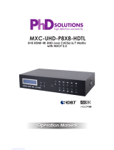
6.1 Front Panel
POWER
CV COMP
PC 1PC 2PC 3 HDMI 1 HDMI 2 HDMI 3
MENU
XGA
ENTER
-
+
720P
-
+
EL-7500V
2 3 4 5 61
1
POWER Button & LED: Press this button to power the unit on or place
it into stand-by mode. The LED will be lit when the unit is receiving
power.
Note: The power switch on the back of the unit must also be in the “On”
position for the unit to receive power.
2
IR Window: Accepts IR signals from the included IR remote for control
of this unit only.
3
CV/COMP/PC 1~3/HDMI 1~3 Buttons & LEDs: Press any of these
buttons to switch immediately to the corresponding input. An LED
will illuminate to indicate which source is currently selected.
4
MENU Button: Press to enter the OSD menu, or to back out from
menu items.
5
− & + Buttons: Press to navigate or to adjust selections within the
OSD menu.
6
ENTER Button: Press to confirm a selection within the OSD or to go
deeper into a menu item.
Note: Pressing “ENTER” and “+” together will reset the output resolution to
XGA (1024×768@60Hz). Pressing “ENTER” and “−” together will reset the
output resolution to 720p@60Hz.

9
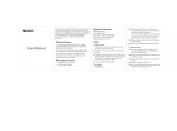
6.2 Rear Panel
RS-232 BYPASS RS-232
COAX. AUDIO
LAN
AUDIO
INPUT
SERVICE
HDMI HDMI 1 HDMI 2 HDMI 3PC 1PC 2PC 3Cr/Pr Cb/Pb YRLCVPOWER
DC 24V
PC/HD
OUTPUT
IR
BLASTER
IR
RL
EXTENDER
CAT5e/6/7
OUTPUT
1 7
8
9 10 13
2 3 4 5 6
11 12 14
1
CAT5e/6/7 OUT: Connect to a compatible HDBaseT Receiver with a
single Cat.5e/6/7 cable for transmission of all data signals.
HDMI OUT: Connect to an HDMI TV, monitor or amplifier for digital
video and audio output.
PC/HD OUT: Connect to a monitor/display for video output. For HD
(Component) output, use the supplied D-Sub 9-pin to 3 RCA adaptor
cable for HD resolutions from 480p~1080p.
Note: When the selected HDMI input source signal has HDCP content the
VGA/Component output will not display any image.
2
IR EXTENDER: Connect to the provided IR Extender to extend the
IR control range of remotely located devices. Ensure that the remote
being used is within direct line-of-sight of the IR Extender.
3
IR BLASTER: Connect to an IR Blaster to transmit IR signals to devices
within direct line-of-sight of the IR Blaster.
4
RS-232 BYPASS: Connect to a PC, laptop or other serial control device
for the extension of RS-232 signals across the HDBaseT connection.
5
RS-232: Connect directly to a PC, laptop or other serial control device
to send RS-232 commands to control the unit.
6
COAX OUT: Connect to an amplifier or active speakers for digital
audio output.
Note: When the AUDIO SOURCE setting is set to “AUTO” the coaxial output
supports passing standard HDMI 1.2 bitstream formats.
AUDIO OUT: Connect to an amplifier or active speakers for audio
output in stereo format.
Note: If the source format is bitstream, this output will be muted
automatically.
7
HDMI IN 1~3: Connect to HDMI source equipment such as media
players, game consoles or set-top boxes.

10
AUDIO IN 1~3: Connect to the stereo analogue output of the device
connected to the paired HDMI input port.
Note: If the AUDIO SOURCE setting is set to “AUTO” and the HDMI input
contains audio, it will have priority over the analogue input.
8
PC IN 1~3: Connect to VGA source equipment such as a PC or laptop.
AUDIO IN 4~6: Connect to the stereo analogue output of the device
connected to the paired VGA input port.
9
YPbPr & L/R IN: Connect to component (YPbPr) video source
equipment with stereo audio such as DVD players or set-top boxes.
10
CV & L/R IN: Connect to composite video source equipment with
stereo audio such as DVD players or VCRs.
11
LAN: Connect directly, or through a network switch, to your PC/
laptop to control the unit via Telnet/WebGUI and to extend the
network to both ends of the HDBaseT connection.
12
SERVICE: Reserved for manufacturer use only.
13
POWER Switch: Flip this switch to provide power to the unit or to turn
it completely off.
Note: This unit’s power stand-by functionality will not work if this switch is
in the “Off” position.
14
DC 24V: Plug the 24V DC power adapter into this port and connect it
to an AC wall outlet for power.

11
6.3 Remote Control
1
POWER: Press this button to power the unit on or
place it into stand-by mode.
2
HDMI 1~3/PC 1~3/CV/COMP: Press any of
these buttons to switch immediately to the
corresponding input.
3
MENU: Press this button to enter the OSD menu.
4
EXIT: Press this button to exit the menu or the
current selection in the OSD menu.
5
OK/
/
/
/
& VOL/−/+: Press OK to confirm the
selection or press the arrow buttons to navigate the
OSD menu. When the OSD menu is not active, use
the LEFT/RIGHT (
◄/►
) buttons to control the volume level.
6
AUTO ADJUST: Press this button to activate the Auto Adjust function
for VGA sources.
7
RESET: Press this button to reset the device back to the default
settings.
6.4 IR Cable Pinouts
3
1
2
Infrared
Power
Ground
IR Extender
3
1
2
IR Blaster
Power
Infrared
NC
2
1
4
3
5
7
6

12
6.5 OSD Menu
All functions of this unit can be controlled by using the OSD (On Screen
Display) which is activated by pressing the MENU button on the front of
the unit. Use the + (Plus), − (Minus), and ENTER buttons to navigate the
OSD menu. Press the MENU button to back out from any menu item and
then press it again to close the menu.
MAIN MENU
Display
Color
Audio
Setup
Information
The individual functions of the OSD will be introduced in the following
section. Items marked in BOLD are the factory default settings.

13
DISPLAY
2ND LEVEL 3RD LEVEL 4TH LEVEL
Output 640×480 60
800×600 60
1024×768 60
1280×768 60
1360×768 60
1280×720 60
1280×800 60
1280×1024 60
1440×900 60
1400×1050 60
1680×1050 60
1600×1200 60
1920×1080 60
1920×1200 60
Output 1280×720p 60
1920×1080i 60
1920×1080p 60
720×576p 50
1280×720p 50
1920×1080i 50
1920×1080p 50
Size Over Scan
FULL
Follow Input
Pan Scan
Letter Box

14
DISPLAY
2ND LEVEL 3RD LEVEL 4TH LEVEL
Size (Cont.) Under 2
Under 1
Mode Info Off
INFO
On
Input HDCP Off
ON
PC (PC Sources Only) Auto Setup
H Position
V Position
Phase
Clock
WXGA/XGA XGA
WXGA
Reset
1) Output: Selects the scaled output resolution to use.
2) Size: Selects the aspect ratio to use when outputting the source. “Full”
stretches the source to fill the output resolution, regardless of the original
aspect ratio, while “Follow Input” will always attempt to retain the original
source’s correct aspect ratio by adding black bars if necessary.
3) Mode Info: Enable or disable the information OSD. Selecting “INFO”
will result in the information display being visible after a source or
resolution change for only a short while.
4) Input HDCP: Enables or disables HDCP support for all HDMI inputs.
5) PC: These settings control the input specifications to use with the VGA
inputs. Activating the Auto Setup function forces the unit to attempt to
detect the correct values. Selecting reset will reset all VGA input settings.
Note: The "Auto Setup" function requires a VGA source with a bright, edge-
to-edge, image to accurately judge the dimensions of the signal.

15
COLOR
2ND LEVEL 3RD LEVEL 4TH LEVEL
Contrast 0~60 (30)
Brightness 0~60 (30)
Color R 0~1023 (512)
G 0~1023 (512)
B 0~1023 (512)
R Oset 0~1023 (512)
G Oset 0~1023 (512)
B Oset 0~1023 (512)
Hue 0~60 (30)
Saturation 0~60 (30)
Sharpness 0~30 (0)
NR OFF
Low
Middle
NR High
1) Contrast: Provides control over the overall contrast of the scaled
output image.
2) Brightness: Provides control over the overall brightness of the scaled
output image.
3) Color (R/G/B): These controls provide control over the red, green, and
blue color level of the scaled output.
Color (R/G/B Offset): These controls provide control over the red,
green, and blue color offset level of the scaled output.
4) Hue: Provides control over the hue shift of the scaled output image.
5) Saturation: Provides control over the color saturation level of the
scaled output image.
6) Sharpness: Provides control over the amount of sharpness processing
to apply to the scaled output image.
7) NR: Provides control over the aggressiveness of the digital noise
reduction processing when applied to the scaled output image.
Selecting “Off” disables all noise reduction processing.

16
AUDIO
2ND LEVEL 3RD LEVEL
Volume 0~100 (100)
Delay OFF
40ms
110ms
150ms
Sound ON
Mute
Source (For HDMI inputs only) AUTO
Ext.
1) Volume: Provides control over the volume level of all audio outputs.
2) Delay: This control sets the amount of audio delay to use, in
milliseconds. Selecting “Off” will disable audio delay completely.
3) Sound: Mutes or unmutes all audio outputs.
4) Source: Selects the audio source selection method for the HDMI
inputs. Selecting “Auto” will prioritise HDMI audio, if present, over
audio from the associated analogue audio inputs. Selecting “EXT.” will
force the HDMI inputs to use the associated analogue audio inputs.

17
SETUP
2ND LEVEL 3RD LEVEL
Factory Reset
Key Lock OFF
On
Power Save OFF
On
IP Mode DHCP
Static
Set Static IP IP Address: 192.168.0.1
Subnet Mask: 255.255.255.0
Def. Gateway: 192.168.1.254
Free Run Color Black
BLUE
1) Factory Reset: Selecting this will reset the unit’s settings back to their
factory defaults.
2) Key Lock: Enable or disable the front panel key lock. When enabled,
no inputs or settings can be adjusted using the front panel buttons
other than disabling the key lock setting itself.
3) Power Save: Enabling this function will cause the unit to
automatically switch into stand-by mode if there is no live signal, and
no user interaction for a period of 3 minutes.
4) IP Mode: Select the IP address acquisition mode. When the unit is set
to DHCP mode it will attempt to automatically obtain an IP address
from a DHCP server. When set to Static mode the unit will use the user
defined static IP information.
5) Set Static IP: Manually set the IP address, netmask and gateway
address to use when the unit is in Static IP mode.
6) Free Run Color: Selects the free run color to use when no live input
source is detected.

18
INFORMATION
2ND LEVEL 3RD LEVEL
Input
[Current Status Details]
Output
Revision
IP Address
1) Information: This screen displays information about the unit’s current
state, input and output status, IP address, as well as the current
firmware version.

19
6.6 WebGUI Control
Device Discovery APP
Please obtain the “Device Discovery” software from your authorised dealer
and save it in a directory where you can easily nd it.
Connect the unit and your PC/Laptop to the same active network and ex-
ecute the “Device Discovery” software. Click on “Find Devices on Network”
and a list of devices connected to the local network will show up indicat-
ing their current IP address.
By clicking on one of the listed devices you will be presented with the
network details of that particular device.
1) IP Mode: If you choose, you can alter the static IP network settings for
the device, or switch the unit into DHCP mode to automatically obtain
proper network settings from a local DHCP server. To switch to DHCP
mode, please select DHCP from the IP mode drop-down, then click
“Save” followed by “Reboot”.
2) WebGUI Hotkey: Once you are satised with the network settings,
you may use them to connect via Telnet or WebGUI. The network
information window provides a convenient link to launch the WebGUI
directly.
Note: The unit’s default IP address is 192.168.1.50.

20
WebGUI Overview
All primary functions of this unit are controllable via the built-in WebGUI.
These controls are presented within a single main page. After connect-
ing to the unit’s IP address in a web browser, the main control web page
will display, allowing direct control of the unit. If desired, the numerical
value for many of the items can be entered directly by typing it in the box
above the slider bar. Press “Enter” to accept the newly entered value.
Note: If the IP address is changed then the IP address required for WebGUI or
Telnet access will also change accordingly. Consult the OSD’s Information tab
to view the current IP settings if necessary.
POWER
This section allows for the unit to be powered ON or placed into stand-by
mode (OFF).
Page is loading ...
Page is loading ...
Page is loading ...
Page is loading ...
Page is loading ...
Page is loading ...
Page is loading ...
Page is loading ...
Page is loading ...
Page is loading ...
Page is loading ...
Page is loading ...
Page is loading ...
Page is loading ...
Page is loading ...
Page is loading ...
Page is loading ...
Page is loading ...
Page is loading ...
Page is loading ...
/