ESAB Origo™ Arc 400 User manual
- Category
- Welding System
- Type
- User manual
This manual is also suitable for

GB
AE
S
B
Origo
TM
Arc
250/300/400
Bruksanvisning Instrucciones de uso
Brugsanvisning Instruzioni per l΄uso
Bruksanvisning Manual de instruções
Käyttöohjeet Οδηγίες χρήσεως
Instruction manual
Инструкция
Betriebsanweisung Instrukcja obslugi
Manuel d΄instructions Návod k používání
Gebruiksaanwijzing Kezelési utasítások
0700 160 033 Valid for serial no. 316-xxx-xxxx

35
GB
1 DIRECTIVE ........................................................................................36
2 SAFETY...............................................................................................36
3 INTRODUCTION ................................................................................38
3.1 Equipment ...................................................................................38
3.2 Field of application ......................................................................38
4 TECHNICAL DATA ............................................................................38
4.1 Static characteristics ..................................................................39
5 INSTALLATION ..................................................................................40
5.1 Placing .........................................................................................40
5.2 Lifting instructions ........................................................................40
5.3 Mains power supply .....................................................................40
6 OPERATION ......................................................................................41
6.1 Start-up ........................................................................................41
6.2 Overload protection .....................................................................41
7 MAINTENANCE .................................................................................41
8 FAULT TRACING ...............................................................................42
9 ORDERING OF SPARE PARTS .......................................................42
Diagram Origo
TM
Arc 250/300 ...................................................................131
Diagram Origo
TM
Arc 400 ..........................................................................131
Spare parts list ..........................................................................................132

36
GB
1 DIRECTIVE
DECLARATION OF CONFORMITY
ESAB Welding Equipment AB, S-695 81 Lax
å
, Sweden, declares that welding power source Origo
TM
Arc
250/300/400
from serial number 316 000 0001 onwards, conforms to standard EN 60974-1, in accordance with the requirements of
directive (73/23/EEC) and appendix (93/68/EEC) and with standard EN 50199, in accordance with the requirements of
directive (89/336/EEC) and appendix (93/68/EEC).
Lax
å
2003
Henry Selenius
Vice President
ESAB AB ARC Equipment
695 81 Lax
å
SWEDN Tel: + 46 584 81000 Fax: +46 584 411924
2 SAFETY
Users of ESAB welding equipment have the ultimate responsibility for ensuring that anyone who works
on or near the equipment observes all the relevant safety precautions. Safety precautions must meet the
requirements that apply to this type of welding equipment. The following recommendations should be
observed in addition to the standard regulations that apply to the workplace.
All work must be carried out by trained personnel well-acquainted with the operation of the welding
equipment. Incorrect operation
o
f th
e
equipment may lead hazardous situations which can result in
injury to the operator and damage to the equipment.
1. Anyone who uses the welding equipment must be familiar with:
• its operation
• location of emergency stops
• its function
• relevant safety precautions
• welding
2. The operator must ensure that:
• no unauthorised person is stationed within the working area of the equipment when it is started
up.
• no-one is unprotected when the arc is struck
3. The workplace must:
• be suitable for the purpose
• be free from draughts
4. Personal safety equipment
• Always wear recommended personal safely equipment, such as safety glasses, flame-proof
clothing, safety gloves.
• Do not wear loose-fitting items, such as scarves, bracelets, rings, etc., which could become
trapped or cause burns.
5. General precautions
• Make sure the return cable is connected securely.
• Work on high voltage equipment
may only be curried out by a qualified electrician.
• Appropriate fire extinguishing equipment must be clearly marked and close at hand.
• Lubrication and maintenance must
not
be carried out on the equipment during operation.

37
GB
WARNING
ARC WELDING AND CUTTING CAN BE INJURIOUS TO YOURSELF AND OTHERS. TAKE
PRECAUTIONS WHEN WELDING. ASK FOR YOUR EMPLOYER’S SAFETY PRACTICES WHICH
SHOULD BE BASED ON MANUFACTURER’S HAZARD DATA.
ELECTRICAL SHOCK - Can kill
•
Install and earth the welding unit in accordance with applicable standards.
•
Do not touch live electrical parts or electrode with bare skin, wet gloves or wet clothing.
•
Insulate yourself from earth and the workpiece.
•
Ensure your working stance is safe.
FUMES AND GASES – Can be dangerous to health
•
Keep your head out of the fumes.
•
Use ventilation, extraction at the arc, or both, to keep fumes and gases from your breathing zone and
the general area.
ARC RAYS – Can injure
eyes and burn skin.
•
Protect your eyes and body. Use the correct welding screen and filter lens and wear protective clothing.
•
Protect bystanders with suitable screens or curtains.
FIRE HAZARD
•
Sparks (spatter) can cause fire. Make sure therefore that there are no inflammable materials nearby.
NOISE – Excessive noise can damage hearing
•
Protect your ears. Use earmuffs or other hearing protection.
•
Warn bystanders of the risk
MALFUNCTION – Call for expert assistance in the event of malfunction,
READ AND UNDERSTAND THE INSTRUCTION MANUAL BEFORE INSTALLING OR OPERATING.
PROTECT YOURSELF AND OTHERS!
WARNING!
Read and understand the instruction manual
before installing or operating.
WARNING!
Do not use the power source for thawing frozen pipes.
Note! This product is solely intended for arc welding.
Do not dispose of electrical equipment together with normal waste!
In observance of European Directive 2002/96/EC on Waste Electrical and Electronic
Equipment and its implementation in accordance with national law, electrical equipment that
has reached the end of its life must be collected separately and returned to an
environmentally compatible recycling facility. As the owner of the equipment, you should get
information on approved collection systems from our local representative.
By applying this European Directive you will improve the environment and human health!

38
GB
3 INTRODUCTION
Origo
TM
Arc250, Origo
TM
Arc300 and Origo
TM
Arc400 are moving core power sources
intended for welding with coated electrodes (MMAwelding).
3.1 Equipment
The welding power source is delivered complete with mains cable (5 metres) and
instruction manual.
3.2 Field of application
The welding power source supply direct current, which allows you to weld most alloyed
and non-alloyed steels, stainless steel and cast iron.
Origo
TM
Arc250 and Origo
TM
Arc300 are suitable for welding with coated electrodes
diameter from 1,6 to 5 mm and Origo
TM
Arc400 accepts up to 6 mm diameter.
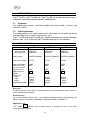
4 TECHNICAL DATA
Origo
TM
Arc250 Origo
TM
Arc300 Origo
TM
Arc400
Permissible load at:
40% duty cycle
100% duty cycle
Setting range
Open circuit voltage
Open circuit power
Power factor cos
ϕ
(at max. current)
Enclosure class
Application class
Weight
Dimensions:
Width
Depth
Height
Height with handle
250A/30V
140A/25,6V
50A/22V-250A/30V
65-75V
490W
0,52
IP23
S
98kg
544mm
510mm
615mm
930mm
285A/31,4V
150A/26V
55A/22,2V-300A/32V
65-75 V
590W
0,54
IP23
S
105 kg
544mm
510mm
615mm
930mm
400A/36V
230A/29,2V
65A/22,6V-400A/36V
70-80V
750W
0,58
IP23
S
158kg
560mm
570mm
770mm
1020mm
Duty cycle
The duty cycle refers to the time as a percentage of a ten-minute period that you can weld at a
certain load without overloading.
Enclosure class
The IP code indicates enclosure class, i.e. the degree of protection against penetration by solid
objects and water. Equipment marked
IP23
is designed for indoor and outdoor use.
Application class
The symbol indicates that the power source is designed for use in areas with
increased electrical hazard.
S

39
GB
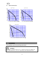
4.1 Static characteristics
(
Origo Arc250
TM TM
Origo Arc300
(
Origo Arc400
TM
5 INSTALLATION
The installation must be executed by a professional.
WARNING!
This product is intended for industrial use. In a domestic environment this product may
cause radio interference. It is the user's responsibility to take adequate precautions.

40
GB
Note!
Connect the power source to the electricity mains with a network impedance Zmax or
lower. If the network impedance is higher, there is a risk of flicker in the illuminators.
Zmax (
Ω
)
Origo
TM
Arc250
0,18
Origo
TM
Arc300
0,11
Origo
TM
Arc400
0,08
5.1 Placing
Place the machine so that there is nothing to prevent the cooling air from passing
through it (air being drawn into the machine through
a grill on the back).
5.2 Lifting instructions
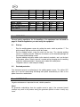
5.3 Mains power supply
• Check that the welding power source is connected for the available mains power
supply before connecting it to the mains.
• The mains cable is connected to the connection block XT1 (using terminals L1,
L2 and L3) and PE-terminal.
• Make sure that the connection blocks XT1 and XT2 are correctly wired for the
mains voltage used. (When delivered welding power source is wired for the
mains voltage 3x400-415V, 50Hz).
• Connect the mains cable to the mains power supply according to the relevant
regulations and install appropriate fuses in the main fuse box.
Origo
TM
Arc250
50/60 Hz
50 Hz
60 Hz
50 Hz
60 Hz
Mains voltage (V)
230
400-415
440-460 500
550
Max. eff. supply current (A)
34 19,5 17 15,5 15,5
Fuse slow (A)
35 20 20 16 16
Mains cable area (mm
2
)
4x6 4x4 4x4
4x2,5
4x2,5

41
GB
Origo
TM
Arc300
50/60 Hz
50 Hz
60 Hz
50 Hz
60 Hz
Mains voltage (V)
230
400-415
440-460 500
550
Max. eff. supply current (A)
36 21 18 16 16
Fuse slow (A)
35 25 20 16 16
Mains cable area (mm
2
)
4x6 4x4 4x4
4x2,5
4x2,5
Origo
TM
Arc400
50/60 Hz
50 Hz
60 Hz
50 Hz
60 Hz
Mains voltage (V)
230
400-415
440-460 500
550
Max. eff. supply current (A)
56 32 28 25 25
Fuse slow (A)
63 35 35 25 25
Mains cable area (mm
2
)
4x10 4x6 4x6
4x4
4x4
6 OPERATION
General safety regulations for the handling of the equipment can be found on
page 36. Read through before you start using the equipment!
6.1 Start-up
• Start the welding power source by setting the mains switch to position “I”. The
white lamp will light up and the fan will be started.
• Set the welding current, using the crank on the front. The selected welding
current is shown by the dial. Follow the instructions on the electrode package for
the recommended welding current.
• Connect welding and return cables to the terminals marked + and - on the front
of the power source. Polarity reversal is carried out by changing over the welding
and return cable connections. Connect return cable to the work piece.
• The power source is now ready for welding.
6.2 Overload protection
The thermostat prevents overheating of the welding power source. The yellow LED
lights up in case of overheating. Resetting takes place automatically as soon as the
power source has cooled down.
7 MAINTENANCE
Regular maintenance is important for safe, reliable operation.
Note!
All guarantee undertakings from the supplier cease to apply if the customer himself
attempts any work in the product during the guarantee period in order to rectify any
faults.

42
GB
7.1
Inspection and cleaning
Normally it is sufficient to blow the welding power source clean regularly using dry
compressed air at reduced pressure. In dusty and dirty environment the welding power
source should be cleaned at shorter intervals.
Where necessary, lubricate the chain and sprocket using heat-resistant grease. When
required, the gliding surfaces of the leakage cores can also be smeared with a thin
coating of this grease.
8 FAULT TRACING
Try these recommended checks and inspections before sending for an authorised
service technician.
Type of fault Measure
No arc.
•
Make sure the mains switch is on.
•
Check that the welding and return
cables are properly connected.
•
Make sure the welding current setting is
correct.
The welding current is interrupted in the
course of welding.
•
Check if the thermal cut-out has tripped
(the yellow indicating led on the front
panel is on).
•
Check the mains power supply fuses.
The thermal cut-out trips frequently.
•
Check that the ratings of the welding
power source have not been exceeded
(overload of the power source).
Poor welding result.
•
Check that the welding and return
cables are properly connected.
•
Make sure the welding current setting is
correct.
•
Check that the correct electrodes are
being used.
9 ORDERING OF SPARE PARTS
Origo
TM
Arc 250/300/400 is designed and tested in accordance with the
international and European standards IEC/EN 60 974-1 and EN 50 199.
It is the obligation of the service unit which has carried out the service or repair
work to make sure that the product still conforms to the said standard.
Spare parts may be ordered through your nearest ESAB dealer, see the last page of
this publication. When ordering, please state product type, serial number, designation
and spare part number in accordance with the spare parts list.
This facilitates dispatch and ensures correct delivery.
-
 1
1
-
 2
2
-
 3
3
-
 4
4
-
 5
5
-
 6
6
-
 7
7
-
 8
8
-
 9
9


ESAB Origo™ Arc 400 User manual
- Category
- Welding System
- Type
- User manual
- This manual is also suitable for
Ask a question and I''ll find the answer in the document
Finding information in a document is now easier with AI
Related papers
-
ESAB Origo™ Arc 250 User manual
-
ESAB Mig 500t User manual
-
ESAB Mig 410 User manual
-
-
ESAB Mig C340 PRO User manual
-
ESAB Mig 320 Origo™ User manual
-
ESAB Mig L305, Mig L405 User manual
-
ESAB Mag C140 User manual
-
-
