
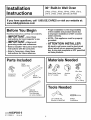
Installation
Instructions
30" Built-In Wall Oven
JTP20, JTP25, JTP28, JTP48, JTPh0, JT912,
JT915, JT952, JT955, ZET938, ZET958
If you have questions, call 1.800.GE.CARES or visit our website at:
www.GEAppliances.com
Before You Begin
Read these instructions carefully and completely.
• IMPORTANT-save these
instructions for local inspector's use.
• IMPORTANT-observe a,
governing codes and ordinances.
• Note to Installer--Be sure to leave these
instructions with the consumer.
• Note to ConsumermKeep these
instructions for future reference,
• Proper installation is the responsibility
of the installer and product failure due
to improper installation is NOT covered
under warranty.
• NOTE--This appliance must be properly
grounded.
• ATTENTION INSTALLER
All electric wall ovens must be hard wired
(direct wired) into an approved junction
box. A plug and receptacle is NOT permitted
on these products.
Parts Included
Screws For
Installation
Metal
Bottom Trim
Plastic
Bottom Trim
Optional
Metal Bottom
Trim Assembly
(on some models)
Materials Needed
__ @ Wireaunts
Strain Relief Clamp Junction
for 1/2" conduit Box €_ _
36" of String
Tools Needed
1/8" Drill Bit and
Electric or Hand Drill
Phillips
Screwdriver
229c4053P505-5
31-10524-5 o6-o4JR

Installation Instructions
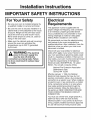
IMPORTANT SAFETY INSTRUCTIONS
For Your Safety
• Be sure your oven is installed properly by
a qualified installer or service technician.
• Be sure the oven is securely installed in a
cabinet that is firmly attached to the house
structure. Weight on the oven door could
cause the oven to tip and result in injury.
Never allow anyone to climb, sit, stand or
hang on the oven door.
• Make sure the cabinets and wall coverings
around the oven can withstand the
temperatures (up to 200°F) generated
by the oven.
WARNING: The electrical
power to the oven supply line
must be shut off while line
connections are being made. Failure
to do so could result in serious injury
or death.
Electrical
Requirements
This appliance must be supplied with the
proper voltage and frequency, and connected
to an individual, properly grounded branch
circuit, protected by a circuit breaker or fuse
having amperage as noted on rating plate.
(Rating Plate is located on oven frame.)
We recommend you have the electrical wiring
and hookup of your oven connected by a
qualified electrician. After installation, have the
electrician show you where your main oven
disconnect is located.
Check with your local utilities for electrical
codes which apply in your area. Failure to wire
your oven according to governing codes could
result in a hazardous condition. If there are no
local codes, your oven must be wired and fused
to meet the requirements of the National
Electrical Code, ANSI/NFPA No. 70-Latest
Edition. You can get a copy by writing:
National Fire Protection Association
Batterymarch Park
Quincy, MA 02269
Effective January 1,1996, the National
Electrical Code requires that new, but not
existing, construction utilize a four-conductor
connection to an electric oven. When installing
an electric oven in new construction, a mobile
home, recreational vehicle or an area where
local codes prohibit grounding through the
neutral conductor, follow the instructions in
the section on NEW CONSTRUCTION AND
FOUR-CONDUCTOR BRANCH CIRCUIT
CONNECTION.
You must use a three-wire, single-phase A.C.
208Y/120 Volt or 240/120 Volt, 60 hertz
electrical system. If you connect to aluminum
wiring, properly installed connectors approved
for use with aluminum wiring must be used.

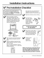
Installation Instructions
Pre-lnstallation Checklist
ALL INSTALLATION INFORMATION
ON THE FOLLOWING PAGES IS TO
BE USED FOR SINGLE AND DOUBLE
OVEN INSTALLATION!
Remove packaging materials.
Check behind hinges and under
false bottom. Remove labels on the
outside of the door, plastic on trims
and panel, all tape around the oven,
and any shipping screws securing
the oven to the base pad.
(-_,_
I
Brdil_rridPan _ Literature
Pack
Open oven door and remove literature
pack, broiler pan and grid, and oven
racks.
Remove Installation Instructions from
literature pack and read them carefully
before you begin.
Be sure to place all literature, Owner's
Manual, Installations, etc. in a safe place
for future reference.
L
Door removal is not a requirement for
installation of the product, but is an
added convenience. To remove the door:
Open the oven door as far as it will go.
[_1_ Push both hinge Hinge_..Ib= Unlocked
locks down toward __/_L. Position
the door frame, Hinge"_
to the unlocked slot _._
position. This may
require a flat blade Hinge
screwdriver. Arm
L_ BY THE HANDLE! _I
[_ lace hands on both sides of
the door, and close the oven
door to the removal position.
This is half way between the
broil stop and fully closed.
[_ ift door up and
out until the
hinge arms
clear the slots.
Hinge Clears Slot
NOTE: The oven door is very heavy, Be sure
you have a firm grip before lifting the oven
door off the hinges, Use caution once the
door is removed, Do not lay the door on its
handle, This could cause dents or scratches,
(Continued on following page)
3

Installation Instructions
[_ Pre-lnstallation Checklistcont.
[_ lace the oven on a table or platform
even with the cutout opening.
(Platform must support 150 Ibs. single,
275 Ibs. double.)
Remove the bottom trim from the top
of the oven. It will be installed at the
end of the installation process. The
trim is wrapped separately and taped
to the top of the unit.

Installation Instructions
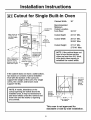
Cutout for Single Built-In Oven
Allow 11/16" for --_._
overlap of oven
over side edges
of cutout
21" _-_
//'"
Allow a minimum of
21" for clearance to
adjacent corners,
drawers, walls, etc.
when door is open
Cutout
Width
__28 1/2" Min.
28 5/8"
_F"Opening
Between
Inside Wall.<
Must Be
At Least
28 1/2" Wide
Allow 1"
minimum for
overlap of oven
top and 11/4"
overlap of oven
bottom of cutout
Cabinet
Width
30"
Recommended
Junction Box
F Location
¢,
22" to
Bottom o1
Junction Box
---1
minimum cutout
location from
floor 32 1/2"
Cabinet Width 30"
Recommended
Minimum
Cutout Location
from Floor
Cutout Depth
Cutout Width
Cutout Height
32 112"
23 112" Min.
28 1/2" Min.
28 5/8" Max.
27 1/4" Min.
27 5116" Max.
NOTE: If the cabinet does not
have a front frame and the
sides are less than 3/4" thick,
shim both sides equally to
establish the cutout width.
If the cabinet does not have a solid bottom,
two braces or runners must be installed
level with the bottom of the cutout to
support the weight of the oven. For single
ovens, the runners and braces must
support 150 Ibs.
NOTE: If marks, blemishes or the
cutout opening are visible above the
installed oven, it may be necessary to
add wood shims under the runners and
front trim until the marks or opening
are covered.
Suitable
Bracing
to Support
Runners --
-_i-_Ove 21 5/8"
r Centerline _-
of Cabinet
-- 2" x 4" or
equivalent
runners
level with
bottom
of cutout
This oven is not approved for
stackable or side by side installation.

Installation Instructions
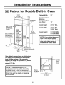
Cutout for Double Built-In Oven
Allow 11/16" for -_
overlap of oven
over side edges
of cutout
Allow a minimum of
21 " for clearance to
adjacent corners,
drawers, walls, etc.
when door is open
21"__"_
Cutout
Width
28 1/2" Min.
"<'-28 5/8" Max. -'_
Opening
Between
Inside Walls
Must Be
At Least
28 112" Wide
Allow 1"
minimum for
overlap of oven
top and 11_"
overlap of
oven bottom
of cutout
Cabinet
Width
_ .5"
I
;d
l
Height
51 13/16" Min.
51 15/16" Max.
Cabinet Width 30"
Recommended
Minimum
Junction Box Cutout Location
Location
j from Floor 12"
Cutout Depth 23 1/2" Min,
-1 Cutout Width 28 112" Min.28 5/8" Max.
47"to Cutout Height 51 13116" Min.
Bottom of
Junction Box 51 15/16" Max.
Recommended
minimum cutout location
from floor 12"
NOTE: If the cabinet does not
have a front frame and the
sides are less than 3/4" thick,
shim both sides equally to
establish the cutout width,
f the cabinet does not have a solid bottom,
two braces or runners must be installed
level with the bottom of the cutout to
support the weight of the oven, For double
ovens, the runners and braces must
support 275 Ibs,
NOTE: If marks, blemishes or the
cutout opening are visible above the
installed oven, it may be necessary to
add wood shims under the runners and
front trim until the marks or opening
are covered.
Suitable
Bracing
to Support
Runners --
-F-----_Ove 21 5/8"-_
r Centerline \
of Cabinet
-- 2" x 4" or
equivalent
runners
level with
bottom
o1 cutout

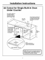
Installation Instructions
Cutout for Single Built-In Oven
Under Counter
Gas or electric cooktops may
be installed over this oven.
See cooktop installation
instructions for cutout size.
See label on top of oven for
approved cooktop models.
\
Top and/or side fillers
may
if unit is positioned
between existing
cabinets. Be sure
they are attached
securely, since they
will anchor the oven
in the cabinet.
28 1/2" Min.
28 5/8" Max.
1
27 1/4" Min.
27 5116" Max.
240V / 208V
Junction Box
Location
Allow 1" overla
top of oven and
11/16" overlap
side edges of
cutout
Gas and electrical connections for
30" gas cooktop must be located
in an adjacent accessible location
to the right. For 36" gas cooktop,
the connections may be made
to the left.
I'LII
22" Min. 36"
Above Typical
Support Countertop
Platform Height
314" ~..
.-" Support Platform
Required
I
MUST SUPPORT 150 LBS.
5 9/16"
Reference dimension for
maximum support height with
typical 36" countertop height
NOTE: This oven is not approved to be
installed under a solid disk, induction
or downdraft modular cooktop.

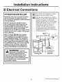
Installation Instructions
Electrical Connections
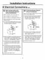
ATTENTION INSTALLER
All electric wall ovens must be hard wired
(direct wired) into an approved junction
box. A plug and receptacle is NOT permitted
on these products.
DO NOT shorten the flexible conduit.
The conduit strain relief clamp must be
securely attached to the junction box
and the flexible conduit must be securely
attached to the clamp. If the flexible
conduit will not fit within the clamp, do not
install the oven until a clamp of the proper
size is obtained.
NOTE TO ELECTRICIAN: The 3 power
leads supplied with this appliance are
UL recognized for connection to heavier
gauge household wiring. The insulation
of these 3 leads is rated at temperatures
much higher than the temperature rating
of household wiring. The current carrying
capacity of the conductor is governed
by the wire gauge and the temperature
rating of the insulation around the wire.
WARNING: Improper
connection of aluminum house
wiring to copper leads can
result in an electrical hazard or fire.
Use only connectors designed for
joining copper to aluminum and follow
the manufacturer's recommended
procedure closely.
Turn off the circuit breaker or remove
fuses to the oven branch circuit.
With the oven supported on a table or
platform in front of the cabinet opening,
connect the flexible conduit to the
electrical junction box as shown below.
Position the conduit in such a manner
that it will lie on top of the oven in
a natural loop when the oven is
installed. You will need to purchase
an appropriate strain relief clamp to
complete the connection of the conduit
to the junction box.
Junction Box
Location
Conduit
48 1/2"
long
Place oven on a
support to assist in
connecting conduit
Strain Relief Clamp
(not included)
must be used at
Junction Box
8 (Continued on following page)

Installation Instructions
IBIElectrical Connections cont
New Construction and
Four-Conductor Branch
Circuit Connection
• When installing in new construction, or
• When installing in a mobile home, or
• When installing in a recreational vehicle, or
• When local codes do not permit grounding
through neutral:
a. Cut the neutral (white) lead from the crimp.
Re-strip the neutral (white) lead to expose
the proper length of conductor.
__ Ground
m_ __Wire
b. Attach the appliance grounding lead (green
or bare copper) in accordance with local
codes. If the residence grounding conductor
is aluminum, see WARNING on page 8.
c. Connect the oven neutral (white) lead to
the branch circuit neutral (white or gray)
in accordance with local codes, using a
wire nut.
d. Connect the oven red lead to the branch
circuit red lead and the oven black lead to
the branch circuit black lead in accordance
with local codes, using wire nuts. If the
residence red, black or white leads are
aluminum conductors, see WARNING on
page 8.
e. Install Junction Box Cover.
Three-Conductor Branch
Circuit Connection
When connecting to a three-conductor branch
circuit, if local codes permit:
a. Connect the bare oven ground conductor
with the crimped neutral (white) lead to
the branch circuit neutral (white or gray
in color), using a wire nut.
[___ round and
I _ Neutral Wires
JcnvCt_onBox
b. Connect the oven red lead to the branch
circuit red lead in accordance with local
codes, using a wire nut.
c. Connect the oven black lead to the branch
circuit black lead in accordance with local
codes, using a wire nut. If the residence
red, black or white leads are aluminum
conductors, see WARNING on page 8.
d. Install Junction Box Cover.

Installation Instructions
Securing the Oven in the Opening
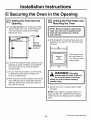
Sliding the Oven Into the
Opening
a. Loop (do not tie) a 36" string around the
conduit before the oven is slid into place.
This will keep the conduit from falling
behind the oven.
Pull out on
string loop
while pushing
the oven into
the cabinet
b. Lift oven into cabinet cutout using the oven
opening as a grip. Carefully push against
oven front frame. Do not push against
outside edges.
c. As you slide the oven back, pull the string
so that the conduit will lie on top of the
oven in a natural loop.
d. When you are sure the conduit is out of the
way, slide the oven 3/4 way back into the
opening. Remove the string by pulling on
one end of the loop.
Drilling the Pilot Holes and
Mounting the Oven
i
a,
NOTE: Before drilling the pilot holes,
make sure the oven is pushed as far
back into the opening as it will go
and centered.
J
Drill through the mounting holes (top and
bottom) of the side trim, for the #8 screws
provided.
Mounting
Hole
The screws must
be a minimum of
1/4" from the front
of the cutout.
WARNING: Mounting
screws must be used. Failure to
do so could result in the oven
falling out of the cabinet causing
serious injury.
i
b. Secure the oven to cabinet with screws
provided.
NOTE: If the cabinet is particle board, you
must use #8 x 3/4" particle board screws.
These may be purchased at any hardware
store.
10 (Continued on following page)

Installation Instructions
To install a single metal bottom trim assembly (on some models), use sections C3 and C4.
To install a metal bottom trim with a plastic bottom trim (on some models), use sections C3-C5.
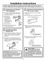
Preparing for the Bottom
Trim Installation
a. With oven installed, take the bottom trim
and center it on the bottom front edge of
the cabinet opening.
b. Using the trim
as a template,
mark the center
of each slot
(two total) where
the mounting holes
will be drilled.
With Lower Trim
in Position, Mark
(2) Mounting Hole
Locations
c. Remove the trim.
d. Drill pilot holes into the center
of each template mark.
\
Remove
Lower Trim
Before
Pre-drilling
Mounting
Holes
Installing the Metal
Bottom Trim
a. Place the bottom metal trim centered over
the pre-drilled mounting holes. Tape the
edges of the trim down to maintain the
alignment.
b. Using two trim screws provided, secure
the bottom trim to the bottom edge of the
cabinet. If a plastic bottom trim is supplied,
proceed to C5.
Side
j-Trim
Trim Screws
Side
Trim -_.
Metal Lower Trim
IMPORTANT: If this unit is ever
removed from the cabinet or the oven
is ever pulled out for service, the trim
must be removed first or damage to
the trim will occur.
Installing the Plastic Bottom
Trim (on some models)
a. Make sure flat side is up on the plastic
bottom trim.
b. Find the key slot on the back of the trim.
Key Hole Slot and Wide Flange at Top
c. Match the key slot with the rivet on the
bottom of the side trim, and lower the trim
onto the rivet.
_r_Tri m Mounting Rivet
on End of Metal Lower Trim
d. Push the trim down, at both ends, until it
snaps securely into place.
Push Trim Down at Both Ends
Until it Snaps Securely Into Place
CAUTION: Be sure you
do not tip the oven forward
during installation or you may
bend the bottom trim. The bottom trim
provides an opening for cooling air to
enter the cabinet. This opening should
never be blocked.
11

Installation Instructions
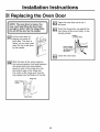
151Replacing the Oven Door
NOTE: The oven door is heavy. You
may need help lifting the door high
enough to slide it into the hinge slots.
Do not lift the door by the handle.
= /
Lift the oven door by
placing one hand on
each side. The door is
heavy, so you may need
help. Do not lift the door
by the handle.
With the door at the same angle as
the removal position (half way between
the closed and broil stop position,
seat the notch of the hinge arm into
the bottom edge of the hinge slot.
The notch of the hinge arm must be
fully seated into the bottom of the slot.
Bottom Edge
of Slot
Hinge Arm
/t
Hinge Notch
_'-_ Open the oven door as far as it
will open.
_"_ Push the hinge locks up against the
front frame of the oven cavity, to the
locked position.
Hinge in
Locked Position
Notch of Hinge
Securely Fitted
into Bottom
Hinge Slot
_'-_ Close the oven door.
12

Installation Instructions
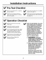
Pre-Test Checklist
Remove all protective film, if present,
and any stickers.
Check to be sure that all wiring is
secure and not pinched or in contact
with moving parts.
[_ heck that the bottom trim is installed
properly (see page 11).
[_ heck to be sure the mounting screws
are installed and flush with the side trim
(see page 10).
Operation Checklist
Remove all items from the inside
of the oven.
Check that conduit is securely
connected to the junction box.
Turn on the power to the oven. (Refer
to your Owner's Manual.) Verify that
the bake and broil units, and all
cooking functions operate properly.
Check that the circuit breaker is not
tripped nor the house fuse blown.
See your Owner's Manual for
troubleshooting list.
NOTE TO ELECTRICIAN: The power
leads supplied with this appliance
are UL recognized for connections
to larger gauge household wiring.
The insulation of these leads is
rated at temperatures much higher
than the temperature rating of
household wiring. The current
carrying capacity of a conductor
is governed by the wire gauge and
also the temperature rating of the
insulation around the wire.
NOTE: ALUMINUM WIRING
A.
a.
WARNING: IMPROPER
CONNECTION OF ALUMINUM
HOUSE WIRING TO THE COPPER
LEADS CAN RESULT IN AN
ELECTRICAL HAZARD OR FIRE.
Splice copper wires to aluminum
wiring using special connectors
designed and UL approved for
joining copper to aluminum,
and follow the manufacturer's
recommended connector
procedure closely.
NOTE: Wire used, location and
enclosure of splices, etc., must
conform to good wiring practice
and local codes.
13

NOTES
14

NOTES
15

NOTES
16
-
 1
1
-
 2
2
-
 3
3
-
 4
4
-
 5
5
-
 6
6
-
 7
7
-
 8
8
-
 9
9
-
 10
10
-
 11
11
-
 12
12
-
 13
13
-
 14
14
-
 15
15
-
 16
16


Ask a question and I''ll find the answer in the document
Finding information in a document is now easier with AI
Related papers
-
GE JRP20WJWW Installation guide
-
GE Profile JT912WFWW User manual
-
GE JT955SKSS Installation guide
-
GE JKP35SP1SS Installation guide
-
GE PT970WM1WW Installation guide
-
-
-
GE JTP86SF1SS Installation guide
-
GE JKP86BF1BB Installation guide
-
GE JT3800SH4SS Installation guide
Other documents
-
Kenmore 91147704200 Installation guide
-
Unbranded 165-SSCHFO-50 Operating instructions
-
Everbilt 165-SCH-FO-40 Installation guide
-
Kenmore 91147759200 Installation guide
-
Summit SEW24SS Installation guide
-
-
Gianni Industries GL-80F Installation guide
-
-
Yes PK7500DFBB Installation guide
-
Yes CT9070SHSS Installation guide