TRIANGLE TUBE Prestige Operating instructions
- Category
- Water heaters & boilers
- Type
- Operating instructions
This manual is also suitable for

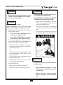
WARNING
Warranty Registration Card must be filled out by the customer and mailed within thirty (30) days of
installation in order to gain warranty coverage.
When receiving the PRESTIGE Excellence unit, any claims for damage or shortage in shipment must
be filed immediately against the transportation company by the consignee.
Leave all documentation received with appliance with owner for future reference.
* I N S T A L L A T I O N A N D M A I N T E N A N C E *
* I N S T A L L A T I O N A N D M A I N T E N A N C E *
2010-28 Manual Prestige Excellence
If the information in this manual is not followed exactly, a fire or explosion
may result causing property damage, personal injury or death.
FOR YOUR SAFETY
• Do not store or use gasoline or other flammable vapors and liquids in the vicinity
of this or any other appliance.
• WHAT TO DO IF YOU SMELL GAS
- Do not try to light any appliance
- Do not touch any electrical switch; do not use any phone in your building.
- Immediately call your gas supplier from a neighbor’s phone. Follow the gas
supplier’s instructions.
- If you cannot reach your gas supplier, call the fire department.
Installation and service must be performed by a qualified installer, service agency or
the gas supplier.
prestige
Water Boiler
Excellence
Revised Date: 06/9/10
Part 1 of 2
NOTICE

This manual outlines the requirements for installation of the PRESTIGE Excellence. Those require-
ments include Boiler Piping, Venting/Combustion Air, Start-Up and Maintenance.
- For detailed instructions regarding the installation of the vent/combustion air system reference the
PRESTIGE Vent Supplement and/or the various optional vent kit instructions.
- For instructions regarding the PRESTIGE Excellence Domestic Water Heater Installation require-
ments and piping, reference the PRESTIGE Excellence Indirect Water Heater Manual beginning
after page 70 of PRESTIGE Excellence Water Boiler Manual.
The PRESTIGE Vent Supplement is included in the unit’s installation envelope. For instructions or
information regarding the various optional vent kits contact the Engineering Department at Triangle
Tube.
WARNING
WARNING

PRODUCT AND SAFETY INFORMATION
Definitions. . . . . . . . . . . . . . . . . . . . . . . . . . . . . . . . . . . . . . . . . . . . . . . . . . . 1
Product and Safety Information . . . . . . . . . . . . . . . . . . . . . . . . . . . . . . . . . . 2
SECTION I - PRE-INSTALLATION ITEMS
Code Compliance . . . . . . . . . . . . . . . . . . . . . . . . . . . . . . . . . . . . . . . . . . . . . 3
Determining Product Location . . . . . . . . . . . . . . . . . . . . . . . . . . . . . . . . . . . 3
Boiler Replacement. . . . . . . . . . . . . . . . . . . . . . . . . . . . . . . . . . . . . . . . . . . . 3
Recommended Clearances . . . . . . . . . . . . . . . . . . . . . . . . . . . . . . . . . . . . . . 4
Residential Garage Installations . . . . . . . . . . . . . . . . . . . . . . . . . . . . . . . . . 4
Boiler Freeze Protection Feature . . . . . . . . . . . . . . . . . . . . . . . . . . . . . . . . . 4
SECTION II - COMBUSTION AIR AND VENTING
Combustion Air Contamination . . . . . . . . . . . . . . . . . . . . . . . . . . . . . . . . . . 5
Ventilation and Combustion Air Requirements - Direct Vent . . . . . . . . . . . 6
Ventilation and Combustion Air Requirements - Category IV . . . . . . . . . . 6
Methods of Accessing Combustion Air into a Space - Category IV . . . . . . 7
- Indoor Combustion Air. . . . . . . . . . . . . . . . . . . . . . . . . . . . . . . . . . 7
- Outdoor Combustion Air . . . . . . . . . . . . . . . . . . . . . . . . . . . . . . . . 7-8
- Combination of Indoor and Outdoor Combustion Air. . . . . . . . . . 8-9
Combustion Air and Vent Piping . . . . . . . . . . . . . . . . . . . . . . . . . . . . . . . . . 9
Removal of an Existing Boiler from a Common Vent System . . . . . . . . . . 10
Commonwealth of Massachusetts Installation . . . . . . . . . . . . . . . . . . . . . . . 11
SECTION III - UNIT PREPARATIONS
Handling Instructions . . . . . . . . . . . . . . . . . . . . . . . . . . . . . . . . . . . . . . . . . . 12
Wall Mounting Installation . . . . . . . . . . . . . . . . . . . . . . . . . . . . . . . . . . . . . . 12
Wall Mounting Guidelines . . . . . . . . . . . . . . . . . . . . . . . . . . . . . . . . . . . . . . 12
Stud Walls - Installation . . . . . . . . . . . . . . . . . . . . . . . . . . . . . . . . . . . . . . . 12
Wall Bracket Installation - Solid Walls . . . . . . . . . . . . . . . . . . . . . . . . . . . . 13
Boiler Mounting . . . . . . . . . . . . . . . . . . . . . . . . . . . . . . . . . . . . . . . . . . . . . . 13
SECTION IV - BOILER PIPING
General Piping Requirements . . . . . . . . . . . . . . . . . . . . . . . . . . . . . . . . . . . . 14
Pressure Relief Valve . . . . . . . . . . . . . . . . . . . . . . . . . . . . . . . . . . . . . . . . . . 14
Low Water Cut Off Device. . . . . . . . . . . . . . . . . . . . . . . . . . . . . . . . . . . . . . 14
Additional Limit Control . . . . . . . . . . . . . . . . . . . . . . . . . . . . . . . . . . . . . . . 16
Table of Contents
i

Table of Contents
ii
Backflow Preventer. . . . . . . . . . . . . . . . . . . . . . . . . . . . . . . . . . . . . . . . . . . . 16
Boiler System Piping Applications. . . . . . . . . . . . . . . . . . . . . . . . . . . . . . . . 16
Expansion Tank and Makeup Water . . . . . . . . . . . . . . . . . . . . . . . . . . . . . . . 16-17
Diaphragm Expansion Tank . . . . . . . . . . . . . . . . . . . . . . . . . . . . . . . 17
Closed-Type Expansion Tank . . . . . . . . . . . . . . . . . . . . . . . . . . . . . 17
Circulator . . . . . . . . . . . . . . . . . . . . . . . . . . . . . . . . . . . . . . . . . . . . . . . . . . . 17
Sizing Primary Piping. . . . . . . . . . . . . . . . . . . . . . . . . . . . . . . . . . . . . . . . . . 17
System Piping - Zone Circulators. . . . . . . . . . . . . . . . . . . . . . . . . . . . . . . . . 17
System Piping - Zone Valves . . . . . . . . . . . . . . . . . . . . . . . . . . . . . . . . . . . . 17
System Piping - Through Boiler. . . . . . . . . . . . . . . . . . . . . . . . . . . . . . . . . . 18
System Piping - Radiant Heating . . . . . . . . . . . . . . . . . . . . . . . . . . . . . . . . . 18
System Piping - Special Applications. . . . . . . . . . . . . . . . . . . . . . . . . . . . . . 18
System Piping - Multiple Units Installation . . . . . . . . . . . . . . . . . . . . . . . . . 18
Central Heating (CH) System Piping Diagrams. . . . . . . . . . . . . . . . . . . . . . 19-21
SECTION V - INSTALLING VENT / COMBUSTION AIR & CONDENSATE DRAIN
Installing Vent and Combustion Air . . . . . . . . . . . . . . . . . . . . . . . . . . . . . . . 22
Installing Condensate Drain Assembly. . . . . . . . . . . . . . . . . . . . . . . . . . . . . 22-23
SECTION VI - GAS PIPING
Gas Supply Piping Connection. . . . . . . . . . . . . . . . . . . . . . . . . . . . . . . . . . . 24
Natural Gas
Pipe Sizing -Natural Gas . . . . . . . . . . . . . . . . . . . . . . . . . . . . . . . . . 25
Natural Gas Supply Pressure Requirements. . . . . . . . . . . . . . . . . . . 25
Propane Gas
Pipe Sizing - Propane Gas . . . . . . . . . . . . . . . . . . . . . . . . . . . . . . . . 26
Propane Gas Supply Pressure Requirements . . . . . . . . . . . . . . . . . . 26
Gas Valve/Venturi Assembly . . . . . . . . . . . . . . . . . . . . . . . . . . . . . . 27
SECTION VII - INTERNAL WIRING
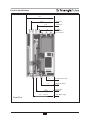
General Requirements. . . . . . . . . . . . . . . . . . . . . . . . . . . . . . . . . . . . . . . . . . 28
Control Module Circulator AMP Ratings. . . . . . . . . . . . . . . . . . . . . . . . . . . 28
Wiring Tool Instructions . . . . . . . . . . . . . . . . . . . . . . . . . . . . . . . . . . . . . . . . 28
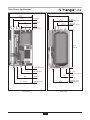
Internal Factory Wiring Diagram . . . . . . . . . . . . . . . . . . . . . . . . . . . . . . . . . 29
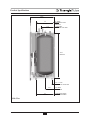
SECTION VIII - EXTERNAL WIRING
Installation Compliance . . . . . . . . . . . . . . . . . . . . . . . . . . . . . . . . . . . . . . . . 30
Line Voltage Connections. . . . . . . . . . . . . . . . . . . . . . . . . . . . . . . . . . . . . . . 30
Thermostat Wiring . . . . . . . . . . . . . . . . . . . . . . . . . . . . . . . . . . . . . . . . . . . . 30

iii
Table of Contents
System Circulator - Zone Valve Application . . . . . . . . . . . . . . . . . . . . . . . . 31
External Modulating Control . . . . . . . . . . . . . . . . . . . . . . . . . . . . . . . . . . . . 31
Outdoor Reset Control . . . . . . . . . . . . . . . . . . . . . . . . . . . . . . . . . . . . . . . . . 31
Additional 24V Limit Wiring . . . . . . . . . . . . . . . . . . . . . . . . . . . . . . . . . . . . 31
External Wiring Diagrams . . . . . . . . . . . . . . . . . . . . . . . . . . . . . . . . . . . . . . 31-33
SECTION IX - START-UP PREPARATION
Check Boiler System Water Chemistry
Water pH Level 6.0 to 8.0 . . . . . . . . . . . . . . . . . . . . . . . . . . . . . . . . 34
Water Hardness Less Than 7 Grains. . . . . . . . . . . . . . . . . . . . . . . . . 34
Chlorinated Water . . . . . . . . . . . . . . . . . . . . . . . . . . . . . . . . . . . . . . . 34
Flush System to Remove Sediment . . . . . . . . . . . . . . . . . . . . . . . . . . . . . . . 34
Check and Test Antifreeze . . . . . . . . . . . . . . . . . . . . . . . . . . . . . . . . . . . . . . 34
Use of Antifreeze in the Boiler System . . . . . . . . . . . . . . . . . . . . . . . . . . . . 35
Filling the Boiler System . . . . . . . . . . . . . . . . . . . . . . . . . . . . . . . . . . . . . . . 35
Check Low Water Cut-Off Device . . . . . . . . . . . . . . . . . . . . . . . . . . . . . . . 36
Check for Gas Leaks. . . . . . . . . . . . . . . . . . . . . . . . . . . . . . . . . . . . . . . . . . . 36
Check Thermostat Circuit. . . . . . . . . . . . . . . . . . . . . . . . . . . . . . . . . . . . . . . 36
Inspection of Condensate Drain Assembly. . . . . . . . . . . . . . . . . . . . . . . . . . 36
SECTION X- START-UP PROCEDURES
Final Checks Before Start-Up. . . . . . . . . . . . . . . . . . . . . . . . . . . . . . . . . . . . 37
PRESTIGE Excellence Start-Up . . . . . . . . . . . . . . . . . . . . . . . . . . . . . . . . . 37
If PRESTIGE Excellence Does Not Start Correctly . . . . . . . . . . . . . . . . . 37
Check the PRESTIGE Excellence and System . . . . . . . . . . . . . . . . . . . . . . 37-38
Operating Instructions. . . . . . . . . . . . . . . . . . . . . . . . . . . . . . . . . . . . . . . . . . 39
Set Boiler CH Target Temperature . . . . . . . . . . . . . . . . . . . . . . . . . . . . . . . . 40
Operation Verification - Space Heating . . . . . . . . . . . . . . . . . . . . . . . . . . . . 40-41
Set DHW Storage Temperature . . . . . . . . . . . . . . . . . . . . . . . . . . . . . . . . . . 41
Operation Verification - Domestic Hot Water . . . . . . . . . . . . . . . . . . . . . . . 41-42
Boiler Control Display
Standby Mode . . . . . . . . . . . . . . . . . . . . . . . . . . . . . . . . . . . . . . . . . . 42-43
Setting the Boiler Parameters
Parameter Mode . . . . . . . . . . . . . . . . . . . . . . . . . . . . . . . . . . . . . . . . 44
Accessing Boiler Information
Information Mode . . . . . . . . . . . . . . . . . . . . . . . . . . . . . . . . . . . . . . . 45
Error (Hard Lockout) Mode . . . . . . . . . . . . . . . . . . . . . . . . . . . . . . . . . . . . . 46

SECTION XI - OUTDOOR RESET CONTROL
Mounting the Outdoor Sensor . . . . . . . . . . . . . . . . . . . . . . . . . . . . . . . . . . . 47
Wiring the Sensor . . . . . . . . . . . . . . . . . . . . . . . . . . . . . . . . . . . . . . . . . . . . . 47
Summer/Winter Switch at Boiler . . . . . . . . . . . . . . . . . . . . . . . . . . . . . . . . . 48
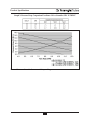
Adjusting Outdoor Reset Curve
CH Maximum Boiler Operating Setpoint (Parameter 4) . . . . . . . . . 48
CH Minimum Boiler Operating Setpoint (Parameter 10) . . . . . . . . 48
CH Reset Curve Coldest Day (Parameter 11) . . . . . . . . . . . . . . . . . 48
CH Reset Curve Warmest Day (Parameter 12) . . . . . . . . . . . . . . . . 49
Entering MCBA Access Code . . . . . . . . . . . . . . . . . . . . . . . . . . . . . . . . . . . 49
Changing a Parameter Setting . . . . . . . . . . . . . . . . . . . . . . . . . . . . . . . . . . . 49
Outdoor Reset Curve Example . . . . . . . . . . . . . . . . . . . . . . . . . . . . . . . . . . . 50
SECTION XII - EXTERNAL MODULATING CONTROL
Wiring the Modulating Controller . . . . . . . . . . . . . . . . . . . . . . . . . . . . . . . . 51
Parameter Adjustment. . . . . . . . . . . . . . . . . . . . . . . . . . . . . . . . . . . . . . . . . . 51
Programming of External Modulating Control . . . . . . . . . . . . . . . . . . . . . . 51
Factory Setting for Parameters . . . . . . . . . . . . . . . . . . . . . . . . . . . . . . . . . . . 52
SECTION XIII - CHECK-OUT PROCEDURES
Check-Out Procedures . . . . . . . . . . . . . . . . . . . . . . . . . . . . . . . . . . . . . . . . . 53
SECTION XIV - INSTALLATION RECORD
Installation Record . . . . . . . . . . . . . . . . . . . . . . . . . . . . . . . . . . . . . . . . . . . . 54
SECTIONS XV - MAINTENANCE SCHEDULE
Service Technician - General . . . . . . . . . . . . . . . . . . . . . . . . . . . . . . . . . . . . 55
Owner Maintenance . . . . . . . . . . . . . . . . . . . . . . . . . . . . . . . . . . . . . . . . . . . 55
SECTION XVI - MAINTENANCE PROCEDURES
Maintenance Procedures
Reported Problems . . . . . . . . . . . . . . . . . . . . . . . . . . . . . . . . . . . . . . 56
Check Surrounding Area. . . . . . . . . . . . . . . . . . . . . . . . . . . . . . . . . . 56
Inspect Burner Area . . . . . . . . . . . . . . . . . . . . . . . . . . . . . . . . . . . . . 56
Check System Piping . . . . . . . . . . . . . . . . . . . . . . . . . . . . . . . . . . . . 56
Clean Condensate Drain Assembly . . . . . . . . . . . . . . . . . . . . . . . . . 57
Table of Contents
iv

Check Ventilation Air Openings . . . . . . . . . . . . . . . . . . . . . . . . . . . . 57
Inspect Vent and Combustion Air Piping . . . . . . . . . . . . . . . . . . . . . 57
Check Boiler System . . . . . . . . . . . . . . . . . . . . . . . . . . . . . . . . . . . . 57
Check Expansion Tank . . . . . . . . . . . . . . . . . . . . . . . . . . . . . . . . . . . 58
Check Boiler Relief Valve . . . . . . . . . . . . . . . . . . . . . . . . . . . . . . . . 58
Inspection of Ignition Electrode . . . . . . . . . . . . . . . . . . . . . . . . . . . . 58
Check Ignition Wiring and Ground Wiring . . . . . . . . . . . . . . . . . . . 58
Check Control Wiring. . . . . . . . . . . . . . . . . . . . . . . . . . . . . . . . . . . . 59
Check Control Settings . . . . . . . . . . . . . . . . . . . . . . . . . . . . . . . . . . . 59
Perform Start-Up and Checkout Procedure . . . . . . . . . . . . . . . . . . . 59
Check Burner Flame . . . . . . . . . . . . . . . . . . . . . . . . . . . . . . . . . . . . . 59
Check Flame Signal . . . . . . . . . . . . . . . . . . . . . . . . . . . . . . . . . . . . . 60
Check Combustion Levels . . . . . . . . . . . . . . . . . . . . . . . . . . . . . . . . 60
Check Flue Gas Temperature . . . . . . . . . . . . . . . . . . . . . . . . . . . . . . 60
Clean Heat Exchanger . . . . . . . . . . . . . . . . . . . . . . . . . . . . . . . . . . . 60-61
Review with Owner . . . . . . . . . . . . . . . . . . . . . . . . . . . . . . . . . . . . . 61
Handling Previously Fired Combustion Chamber Insulation . . . . . 61
REPLACEMENT PARTS
Replacement Parts. . . . . . . . . . . . . . . . . . . . . . . . . . . . . . . . . . . . . . . . . . . . . 62-65
PRODUCT SPECIFICATIONS
Specifications . . . . . . . . . . . . . . . . . . . . . . . . . . . . . . . . . . . . . . . . . . . . . . . . 66-70
Table of Contents
v

Product & Safety Information
1
Indicates the presence of a hazardous
situation which, if ignored, will result in
death, serious injury or substantial
property damage.
Indicates a potentially hazardous situa-
tion which, if ignored, can result in
death, serious injury or substantial
property damage.
Indicates a potentially hazardous situa-
tion which, if ignored, may result in
minor injury or property damage.
Indicates special instructions on installa-
tion, operation or maintenance, which
are important to equipment but not
related to personal injury hazards.
Indicates recommendations made by
Triangle Tube for the installers which
will help to ensure optimum operation
and longevity of the equipment
WARNING
NOTICE
CAUTION
BEST PRACTICE
DANGER
The following terms are used throughout this manual to bring attention to the presence of
potential hazards or important information concerning the product.
Triangle Tube reserves the right to modify the technical specifications and components of
its products without prior notice.
NOTICE
Definitions

2
Do not use this appliance if any part
has been under water. Immediately call
a qualified service technician to inspect
the appliance and to replace any part of
the control system which has been
under water.
WHAT TO DO IF YOU SMELL GAS
- Do not try to light any appliance
- Do not touch any electrical switch; do
not use any phone in your building.
- Immediately call your gas supplier
from a neighbor’s phone. Follow the
gas supplier’s instructions.
- If you cannot reach your gas suppli-
er, call the fire department.
Installation and service must be per-
formed by a qualified installer, service
agency or the gas supplier.
Should overheating occur or the gas
supply fails to shut off, turn OFF the
manual gas control valve external to
the appliance.
DO NOT add cold make up water when
the boiler is hot. Thermal shock can
cause potential cracks in the heat
exchanger.
When servicing the boiler:
- Avoid electrical shock by discon-
necting the electrical supply prior to
performing maintenance.
WARNING
WARNING
WARNING
CAUTION
DANGER
Product & Safety Information
Qualified Installer:
Prior to installing this product read all
instructions included in this manual and all
accompanying manuals/documents with this
appliance. Perform all installation steps
required in these manuals in the proper
order given. Failure to adhere to the guide-
lines within these manuals can result in
severe personal injury, death or substantial
property damage.
Homeowner:
- This product should be maintained /
serviced and inspected annually by a
qualified service technician.
- This manual is intended for use by a
qualified Installer/Service Technician.
Please reference the unit’s model num-
ber and the serial number from the rat-
ing label on the backside of the control
panel when inquiring about service or
troubleshooting.
Triangle Tube accepts no liability for any
damage resulting from incorrect instal-
lation or from the use of components or
fittings not specified by Triangle Tube.
WARNING
NOTICE
NOTICE

Pre-Installation Items
3
SECTION I - Pre-Installation Items
Code Compliance
This product must be installed in accordance to
the following:
- All applicable local, state, national and
provincial codes, ordinances, regula-
tions and laws.
- For installations in Massachusetts -
code requires the boiler to be installed
by a licensed plumber or gas fitter, and
if antifreeze is utilized, the installation
of a reduced pressure backflow preven-
ter device is required in the boiler’s cold
water fill or make up water supply line.
- For installation in Massachusetts
All direct vented appliances must com-
ply with the guidelines as outlined on
page 11.
- The National Fuel Gas Code NFPA54/
ANSI Z 223.1 - Latest edition.
- National Electric Code ANSI/NFPA 70.
- For installations in Canada -“Installation
Code for Gas Burning Equipment”
CGA/B149.1 or B149.2 Canadian
Electrical Code Part 1 CSA C22.1.
- Standards for Controls and Safety
Devices for Automatically Fired Boilers,
ANSI/ASME CSD-1, when required.
The PRESTIGE Excellence boiler gas
manifold and gas controls meet the safe
lighting and other performance require-
ments as specified in ANSI Z21.13 latest
edition.
Determining Product Location
Before locating the PRESTIGE Excellence
check for convenient locations to:
- Heating system piping
- Venting
- Gas supply piping
- Electrical service
Ensure the boiler location allows the combus-
tion air/vent piping to be routed directly through
the building and terminate properly outside with
a minimum amount of length and bends.
Ensure the area chosen for the installation of the
PRESTIGE Excellence is free of any com-
bustible materials, gasoline and other flamma-
ble liquids.
Failure to remove or maintain the area
free of combustible materials, gasoline
and other flammable liquids or vapors
can result in severe personal injury,
death or substantial property damage.
Ensure the PRESTIGE Excellence and its con-
trols are protected from dripping or spraying
water during normal operation or service.
The PRESTIGE Excellence should be
installed in a location so that any water leaking
from the boiler or piping connections or relief
valve will not cause damage to the area sur-
rounding the unit or any lower floors in the
structure.
Boiler Replacement
If the PRESTIGE Excellence is replacing an
existing boiler, the following items should be
checked and corrected prior to installation:
- Boiler piping leaks and corrosion.
- Improper location and sizing of the
expansion tank on the boiler heating
loop.
- If applicable, level and quality of freeze
protection within the boiler system.
WARNING
NOTICE

Pre-Installation Items
Recommended Clearances
The PRESTIGE Excellence is approved for
zero clearance to combustibles, excluding
vent and boiler piping.
- Vent & Boiler Piping - 1/4 inch from
combustible materials.
To provide serviceability to the unit it is
recommended that the following clear-
ances be maintained:
Top boiler jacket - 24 inches.
Front - 24 inches.
Bottom boiler piping - 24 inches.
Rear - 0 inches
Sides - 6 inches
If the clearances listed above cannot be
maintained or the enclosure in which the
boiler is installed is less than 85 cubic feet,
the space must be ventilated. See page 6
for ventilation requirements.
When maintaining zero clearance or less
than recommended clearances, some
product labeling may become hidden
and unreadable
When installing the PRESTIGE
Excellence in a confined space, sufficient
air must be provided for proper combus-
tion and venting and to allow, under
normal operating conditions, proper air
flow around the product to maintain
ambient temperatures within safe limits
to comply with the National Fuel Gas
Code NFPA 54 - latest edition.
Residential Garage Installations
When installing the PRESTIGE Excellence in a
residential garage, the following special precau-
tions per NFPA 54/ANSI Z223.1 must be taken:
- Mount the unit with a minimum 18
inches above the floor level of the
garage. Ensure the burner and ignition
devices / controls are no less than 18
inches above the floor level.
- Locate or protect the unit in a matter
so it cannot be damaged by a moving
vehicle.
Boiler Freeze Protection Feature
The boiler control has an freeze protection fea-
ture built in. This feature monitors the boiler
temperature and responds as follows when no
call for heat is present:
- 46ºF Boiler circulator is ON
- 38ºF Boiler circulator is ON and burner
operates at low fire
- 50ºF Burner OFF and boiler circulator
operates for approximately 10 minutes
The boiler freeze protection feature is
disabled during a hard lockout, however
the CH circulator will operate and the 3-
way valve will open to the CH system.
The boiler freeze protection feature is
designed to protect the boiler and should
be installed in a primary/secondary pip-
ing arrangement. If it is installed in an
unheated space or exposed to water tem-
peratures of 46ºF or less, see Section IV
for primary/secondary piping examples.
See Section IX for antifreeze guidelines.
WARNING
WARNING
NOTICE
CAUTION
CAUTION
BEST PRACTICE
4

Combustion Air and Venting
5
SECTION II - Combustion Air and
Venting
Combustion Air Contamination
If the PRESTIGE Excellence combus-
tion air inlet is located in any area likely
to cause or contain contamination, or if
products, which would contaminate the
air cannot be removed, the combustion
air must be repiped and terminated to
another location. Contaminated com-
bustion air will damage the unit and its
burner system, resulting in possible
severe personal injury, death or substan-
tial property damage.
Do not operate a PRESTIGE Excellence
if its combustion air inlet is located near
a laundry room or pool facility. These
areas will always contain hazardous con-
taminants.
Pool and laundry products and common
household and hobby products often
contain fluorine or chlorine compounds.
When these chemicals pass through the
burner and vent system, they can form
strong acids. These acids can create cor-
rosion of the heat exchanger, burner
components and vent system, causing
serious damage and presenting a possi-
ble threat of flue gas spillage or water
leakage into the surrounding area.
Please read the information listed below.
If contaminating chemicals are located
near the area of the combustion air inlet,
the installer should pipe the combustion
air inlet to an outside area free of these
chemicals per SECTION V of this
installation manual.
Potential contaminating products
- Spray cans containing chloro/fluorocar-
bons
- Permanent Wave Solutions
- Chlorinated wax
- Chlorine - based swimming pool chem-
icals / cleaners
- Calcium Chloride used for thawing ice
- Sodium Chloride used for water soft-
ening
- Refrigerant leaks
- Paint or varnish removers
- Hydrochloric acid / muriatic acid
- Cements and glues
- Antistatic fabric softeners used in
clothe dryers
- Chlorine-type bleaches, detergents, and
cleaning solvents found in household
laundry rooms
- Adhesives used to fasten building prod-
ucts and other similar products
Areas likely to contain these products
- Dry cleaning / laundry areas and estab-
lishments
- Beauty salons
- Metal fabrication shops
- Swimming pools and health spas
- Refrigeration Repair shops
- Photo processing plants
- Auto body shops
- Plastic manufacturing plants
- Furniture refinishing areas and estab-
lishments
- New building construction
- Remodeling areas
- Garages with workshops
WARNING
WARNING

6
Combustion Air and Venting
Ventilation and Combustion Air
Requirements - Direct Vent
A Direct Vent appliance utilizes uncontaminat-
ed outdoor air (piped directly to the appliance)
for combustion)
For Direct Vent installations, involving only the
PRESTIGE Excellence, in which the minimum
service clearances are maintained as listed on
page 4, no ventilation openings are required.
For Direct Vent, zero service clearance installa-
tions involving only the PRESTIGE Excellence,
the space / enclosure must provide two openings
for ventilation. The openings must be sized to
provide 1 square inch of free area per 1,000
BTUH of boiler input. The openings shall be
placed 12 inches from the top of the space and 12
inches from the floor of the space.
For installations in which the PRESTIGE
Excellence shares the space with air movers
(exhaust fan, clothes dryers, fireplaces, etc.)
and other combustion equipment (gas or oil)
the space must be provided with adequate air
openings to provide ventilation and combus-
tion air to the equipment. To properly size the
ventilation / combustion air openings, the
installer must comply with the National Fuel
Gas Code NFPA 54, ANSI Z223.1 for installa-
tions in the U.S or CSA B149.1 and B149.2 for
installations in Canada.
The space must be provided with venti-
lation / combustion air openings proper-
ly sized for all make-up air requirements
(exhaust fans, clothes dryers, fireplaces,
etc.) and the total input of all appliances
located in the same space as the PRES-
TIGE Excellence, excluding the input of
a Direct Vent PRESTIGE Excellence
which uses combustion air directly from
the outside, thus additional free area for
the openings is not required. Failure to
provide or properly size the openings
could result in severe personal injury,
death or substantial property damage.
Ventilation and Combustion Air
Requirements - Category IV
A Category IV appliance utilizes uncontami-
nated indoor or outdoor air (surrounding the
appliance) for combustion.
In order to reduce the potential risks
associated with indoor contaminates
(listed on page 5), flammable vapors and
tight housing construction (little or no
infiltration air), it is recommended to
pipe uncontaminated combustion air
directly from the outdoors to the appli-
ance. This practice also promotes higher
system efficiency by reducing heated
indoor air from being exhausted from
the house and replaced by cold infiltra-
tion air into the house.
For installations in which the PRESTIGE
Excellence shares the space with air movers
(exhaust fan, clothes dryers, fireplaces, etc.) and
other combustion equipment (gas or oil) the
space must be provided with adequate air open-
ings to provide ventilation and combustion air to
the equipment. To properly size the ventilation
/ combustion air openings, the installer must
comply with the National Fuel Gas Code NFPA
54, ANSI Z223.1 for installations in the U.S or
CSA B149.1 and B149.2 for installations in
Canada, as referenced in this section of the man-
ual and titled Methods of Accessing
Combustion Air into a Space.
The space must be provided with venti-
lation / combustion air openings proper-
ly sized for all make-up air requirements
(exhaust fans, clothes dryers, fireplaces,
etc.) and the total input of all appliances,
including the PRESTIGE Excellence
when located in the same space as the
PRESTIGE Excellence. Failure to pro-
vide or properly size the openings could
result in severe personal injury, death or
substantial property damage.
WARNING
WARNING
BEST PRACTICE

7
Combustion Air and Venting
Methods of Accessing Combustion Air Into A
Space - Category IV
Indoor Combustion Air
The methods listed in this section for
accessing Indoor Combustion Air
assume that the infiltration rate is ade-
quate and not less than .40 ACH. For
infiltration rates less than .40 ACH, ref-
erence the NFPA 54 National Fuel Gas
Code for additional guidance.
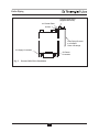
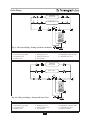
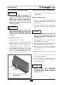
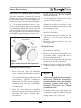
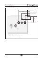
Opening Size and Location
Openings used to connect indoor spaces shall
be sized and located in accordance with the
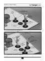
following. See Fig. 1:
- Combining spaces on the same story.
Each opening shall have a minimum
free area of 1 sq. in./1000 Btu/hr of the
total input rating of all gas utilization
equipment in the space, but not less than
100 sq. inches. One opening shall com-
mence within 12 inches of the top, and
one opening shall commence within 12
inches of the bottom of the enclosure.
The minimum dimension of air open-
ings shall be not less than 3 inches.
- Combining spaces in different stories.
The volumes of spaces in different sto-
ries shall be considered as communicat-
ing spaces where such spaces are con-
nected by one or more openings in
doors or floors having a total minimum
free area of 2 sq. in./1000 Btu/hr of
total input rating of all gas utilization
equipment.
Outdoor Combustion Air
Isolating the combustion appliance room
from the rest of the building and bring-
ing in uncontaminated outside air for
combustion and ventilation is always
preferred.
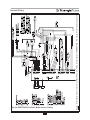
Opening Size and Location
The minimum dimension of air openings shall
be not less than 3 inches
Openings used to supply combustion and ven-
tilation air shall be sized and located in accor-
dance with the following:
One Permanent Opening Method. See Fig. 2
One permanent opening, commencing within 12
in. of the top of the enclosure, shall be provided.
The equipment shall have clearances of at least 1
inch from the sides and 6 in. from the front of the
appliance. The opening shall directly communi-
cate with the outdoors or shall communicate
through a vertical or horizontal duct to the out-
doors or spaces that freely communicate with the
outdoors and shall have a minimum free area of
the following:
- 1sq. in./3000 Btu/hr of the total input
rating of all equipment located in the
enclosures, and
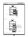
NOTICE
BEST PRACTICE
All Combustion Air from Adjacent
Indoor Spaces Through Indoor
Combustion Openings
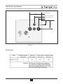
Fig. 1:

8
Combustion Air and Venting
- Not less than the sum of the areas of all
vent connectors in the space.
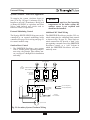
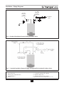
Two Permanent Openings Method.
Two permanent openings, one commencing
within 12 in. of the top and one commencing
within 12 in. of the bottom of the enclosure,
shall be provided. The openings shall commu-
nicate directly, or by ducts, with the outdoors
or spaces that freely communicate with the out-
doors, as follows:
- Where directly communicating with the
outdoors or where communication to the
outdoors is through vertical ducts, each
opening shall have a minimum free area
of 1 sq. in./4000 Btu/hr of total input rat-
ing of all equipment in the enclosure.
See Fig.3.
- Where communicating with the out-
doors is through horizontal ducts, each
opening shall have a minimum free
area of not less than 1 sq.in./2000
Btu/hr of total input rating of all equip-
ment in the enclosure. See Fig. 4.
Combination of Indoor and Outdoor
Combustion Air
Indoor Openings: Where used, openings con-
necting the interior spaces shall comply with
the Indoor Combustion Air section on page 7.
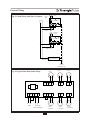
All Combustion Air from Outdoors
Through One Permanent Air
Opening
Fig. 2:
All Combustion Air from Outdoors
Through Ventilated Attic
Fig. 3:
All Combustion Air from Outdoors
through Horizontal Ducts
Fig. 4:

Outdoor Opening(s) Location. Outdoor open-
ing(s) shall be located in accordance with the
Outdoor Combustion Air section.
Outdoor Opening(s) Size. Outdoor opening(s) shall
be calculated in accordance with the following:
- The ratio of the interior spaces shall be
the available volume of all communi-
cating spaces divided by the required
volume.
- The outdoor size reduction factor shall
be 1 minus the ratio of interior spaces.
- The minimum size of outdoor open-
ing(s) calculated in accordance with the
above outdoor air section multiplied by
the reduction factor. The minimum
dimension of air openings shall not be
less than 3 in.
Do not install the PRESTIGE Excellence
into a common vent with other gas or oil
appliances. This may cause flue gas
spillage or appliance malfunction, result-
ing in possible severe personal injury,
death or substantial property damage.
Combustion Air and Vent Piping
The PRESTIGE Excellence requires a
Category IV venting system, which is designed
for pressurized venting and condensate.
The PRESTIGE Excellence is certified per
ANSI Z21.13 as a Category IV or Direct Vent
(sealed combustion) appliance. A Category IV
appliance utilizes uncontaminated indoor or
outdoor air (surrounding the appliance) for
combustion. A Direct Vent appliance utilizes
uncontaminated outdoor air (piped directly to
the appliance) for combustion.
In order to reduce the potential risks
associated with indoor contaminates
(listed on page 5), flammable vapors
and tight housing construction (little or
no infiltration air), it is recommended
to pipe uncontaminated combustion air
directly from the outdoors to the appli-
ance. This practice also promotes higher
system efficiency by reducing heated
indoor air from being exhausted from
the house and replaced by cold infiltra-
tion air into the house.
Install combustion air and vent pipe as
detailed in the PRESTIGE Vent
Supplement included in the boiler
installation envelope. Refer to optional
vent kit instructions for additional vent
installation instructions.
Verify installed combustion air and vent
piping are sealed gas tight and meet all
provided instructions and applicable
codes, failure to comply will result in
severe personal injury of death.
NOTICE
BEST PRACTICE
DANGER
DANGER
Combustion Air and Venting
9

Removal of an Existing Boiler from a
Common Vent System
When an existing boiler is removed from a
common venting system, the common vent-
ing system is likely to be too large for proper
venting of the remaining appliances. At the
time of removal of an existing boiler, the fol-
lowing steps shall be followed with each
appliance remaining connected to the com-
mon venting system placed in operation,
while the other appliances remaining con-
nected to the common venting system are not
in operation.
1. Seal any unused openings in the common
venting system.
2. Visually inspect the venting system for
proper size and horizontal pitch and deter-
mine there is no blockage or restriction,
leakage, corrosion and other deficiencies
which could cause an unsafe condition.
3. Insofar as is practical, close all building
doors and windows and all doors between
the space in which the appliances remain-
ing connected to the common venting sys-
tem are located and other spaces of the
building. Turn on clothes dryers and any
appliance not connected to the common
venting system. Turn on any exhaust fans,
such as range hoods and bathroom
exhausts, so they will operate at maximum
speed. Do not operate a summer exhaust
fan. Close fireplace dampers.
4. Place in operation the appliance being
inspected. Follow the lighting instructions.
Adjust thermostat so appliance will oper-
ate continuously.
5. Test for spillage at the draft hood relied
opening after 5 minutes of main burner
operation. Use the flame of a match or can-
dle, or smoke from a cigarette, cigar or pipe.
6. After it has been determined that each
appliance remaining connected to the
common venting system properly vents
when tested as outlined above, return
doors, windows, exhaust fans, fireplace
dampers, and any other gas-burning appli-
ance to their previous condition of use.
7. Any improper operation of the common
venting system should be corrected so the
installation conforms with the National
Fuel Gas Code, ANSI Z223.1/NFPA 54
and/or CAN/CGA B149, Installation
codes. When resizing any portion of the
common venting system, the common
venting system should be resized to
approach the minimum size as determined
using the appropriate tables in Part II of
the National Fuel Gas Code ANSI
Z223.1/NFPA 54 and/or CAN/CGA B149,
Installation codes.
Do not install the PRESTIGE Excellence
into a common vent with other gas or oil
appliances. This may cause flue gas
spillage or appliance malfunction, result-
ing in possible severe personal injury,
death or substantial property damage.
BEST PRACTICE
DANGER
Combustion Air and Venting
10

11
Combustion Air and Venting
For direct-vent appliances, mechanical-
vent heating appliances or domestic hot
water equipment, where the bottom of the
vent terminal and the air intake is installed
below four feet above grade the following
requirements must be satisfied:
1. If there is not one already present, on
each floor level where there are bed-
room(s), a carbon monoxide detector
and alarm shall be placed in the living
area outside the bedroom(s). The car-
bon monoxide detector shall comply
with NFPA 720 (2005 Edition).
2. A carbon monoxide detector shall be
located in the room that houses the
appliance or equipment and shall:
a. Be powered by the same electrical
circuit as the appliance or equip-
ment such that only one service
switch services both the appliance
and the carbon monoxide detector;
b. Have battery back-up power;
c. Meet ANSI/UL 2034 Standards and
comply with NFPA 720 (2005
Edition); and
d. Have been approved and listed by
the Nationally Recognized Testing
Laboratory as recognized under 527
CMR.
3. A Product-approved vent terminal must
be used, and if applicable, a Product-
approved air intake must be used.
Installation shall be in strict compliance
with the manufacturer’s instructions. A
copy of the installation instructions
shall remain with the appliance or
equipment at the completion of the
installation.
4. A metal or plastic identification plate
shall be mounted at the exterior of the
building, four feet directly above the
location of vent terminal. The plate
shall be of sufficient size to be easily
read from a distance of eight feet away,
and read “Gas Vent Directly Below”.
Installer must provide tag identification
plate and ensure the lettering meets code
requirements.
For direct-vent appliances, mechanical-
vent heating appliances or domestic hot
water equipment, where the bottom of the
vent terminal and the air intake are installed
above four feet above grade the following
requirements must be satisfied:
1. If there is not one already present, on
each floor level where there are bed-
room(s), a carbon monoxide detector
and alarm shall be placed in the living
area outside the bedroom(s). The car-
bon monoxide detector shall comply
with NFPA 720 (2005 Edition).
2. A carbon monoxide detector shall:
a. Be located in the rooms that houses
the appliances or equipment;
b. Be either hard wired or battery
powered or both; and
c. Shall comply with NFPA 720 (2005
Edition)
3. A Product-approved vent terminal must
be used, and if applicable, a Product-
approved air intake must be used.
Installation shall be in strict compliance
with the manufacturer’s instructions. A
copy of the installation instructions
shall remain with the appliance or
equipment at the completion of the
installation.
NOTICE
Commonwealth of Massachusetts Installations Only

12
Unit Preparations
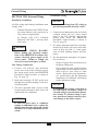
SECTION III - Unit Preparations
Handling Instructions
The PRESTIGE Excellence is generally easier
to handle and maneuver once removed from
the shipping carton and pallet.
To remove the shipping carton and pallet:
Use care not to lift the unit from, or place
the unit on the front plastic control
panel, damage can occur. Use care not to
drop, bump or rotate the boiler upside
down, as damage to the boiler will result.
1. Remove any shipping straps and open the
side of the shipping carton.
2. Slide the unit with the foam inserts out of
the carton.
3. Discard all packing materials.
Wall Mounting Installation
Due to the excessive weight, the PRESTIGE
Excellence should be wall mounted using the
bracket kit provided with the boiler. The
PRESTIGE is not designed for floor installa-
tion. If floor installation is required an optional
floor stand is available through Triangle Tube.
The wall used for mounting the PRES-
TIGE Excellence must be vertically
plumbed and capable of supporting a
minimum 250 pounds [113 Kg]. Failure
to comply with these requirements could
result in personal injury, death or sub-
stantial property damage.
Wall Mounting Guidelines
1. The wall frame kit is designed for stud
spacing of 12 inch or 16 inch on centers.
For unconventional stud spacing, a solid /
secure mounting surface must be provided
for installation of the bracket.
2. DO NOT mount or attempt to mount the
wall bracket to hollow sheet rock or lathe
walls using anchors. Only install boiler to
studs or equivalent wood structure.
3. For applications using solid walls (rock,
concrete, brick, cinder block, etc.), install
the wall bracket using anchors (double
expansion shields) and bolts with washers
provided with the boiler.
4. The boiler is too heavy and bulky for a sin-
gle person to lift and attempt to mount; a
minimum of 2 people is required for
mounting the boiler.
Use extreme care not to drop the boiler
or cause bodily injury while lifting or
mounting the boiler onto the bracket.
Once mounted verify that the boiler is
securely attached to the bracket and
wall. Failure to comply with the above
guidelines could result in property dam-
age, personal injury or death.
Stud Walls -Installation
1. To distribute the weight of the boiler even-
ly when mounting onto a stud wall it is rec-
ommended to use the PRESTIGE Wall
Frame kit.
2. When using the wall frame to mount the
boiler reference the kit installation instruc-
tions and ensure the frame is securely fas-
tened to the wall.
3. If the structure of wall is questionable, in
supporting a minimum weight of 250
pounds [113 Kg.], it is recommended to use
the optional floor stand.
WARNING
WARNING
CAUTION

13
Unit Preparations
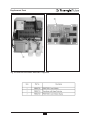
Wall Bracket Installation - Solid Walls
1. Locate the general area of the boiler place-
ment.
2. Place the wall-mounting bracket on the
wall ensuring the upper edge of the bracket
is away from the wall.
3. Level the bracket and use a pencil to mark
the location of the mounting slots on the
wall.
4. Remove the bracket from the wall and drill
a 5/8” diameter hole by 1-3/8” deep posi-
tioned in the center of each mark.
5. Install the anchors (provided) flush or
slightly recessed in the drilled holes with
threaded side facing down.
6. Reposition the bracket on the wall and
align mounting slots/holes. Insert the two
bolts (provided) through the mounting
slots/holes and loosely tighten.
7. Level bracket and tighten bolts securely.
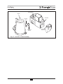
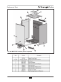
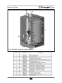
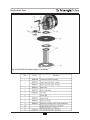
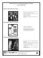
Boiler Mounting
1. Obtain assistance in lifting the boiler onto
the wall bracket.
2. Install the boiler making sure the boiler
mounting lip located along the upper edge
of the rear jacket panel engages the wall-
mounting bracket. Ensure the boiler is
seated properly and is secure.
Page is loading ...
Page is loading ...
Page is loading ...
Page is loading ...
Page is loading ...
Page is loading ...
Page is loading ...
Page is loading ...
Page is loading ...
Page is loading ...
Page is loading ...
Page is loading ...
Page is loading ...
Page is loading ...
Page is loading ...
Page is loading ...
Page is loading ...
Page is loading ...
Page is loading ...
Page is loading ...
Page is loading ...
Page is loading ...
Page is loading ...
Page is loading ...
Page is loading ...
Page is loading ...
Page is loading ...
Page is loading ...
Page is loading ...
Page is loading ...
Page is loading ...
Page is loading ...
Page is loading ...
Page is loading ...
Page is loading ...
Page is loading ...
Page is loading ...
Page is loading ...
Page is loading ...
Page is loading ...
Page is loading ...
Page is loading ...
Page is loading ...
Page is loading ...
Page is loading ...
Page is loading ...
Page is loading ...
Page is loading ...
Page is loading ...
Page is loading ...
Page is loading ...
Page is loading ...
Page is loading ...
Page is loading ...
Page is loading ...
Page is loading ...
Page is loading ...
Page is loading ...
Page is loading ...
Page is loading ...
Page is loading ...
Page is loading ...
Page is loading ...
Page is loading ...
Page is loading ...
Page is loading ...
Page is loading ...
Page is loading ...
Page is loading ...
Page is loading ...
Page is loading ...
Page is loading ...
Page is loading ...
Page is loading ...
Page is loading ...
Page is loading ...
Page is loading ...
Page is loading ...
Page is loading ...
Page is loading ...
Page is loading ...
Page is loading ...
Page is loading ...
Page is loading ...
Page is loading ...
-
 1
1
-
 2
2
-
 3
3
-
 4
4
-
 5
5
-
 6
6
-
 7
7
-
 8
8
-
 9
9
-
 10
10
-
 11
11
-
 12
12
-
 13
13
-
 14
14
-
 15
15
-
 16
16
-
 17
17
-
 18
18
-
 19
19
-
 20
20
-
 21
21
-
 22
22
-
 23
23
-
 24
24
-
 25
25
-
 26
26
-
 27
27
-
 28
28
-
 29
29
-
 30
30
-
 31
31
-
 32
32
-
 33
33
-
 34
34
-
 35
35
-
 36
36
-
 37
37
-
 38
38
-
 39
39
-
 40
40
-
 41
41
-
 42
42
-
 43
43
-
 44
44
-
 45
45
-
 46
46
-
 47
47
-
 48
48
-
 49
49
-
 50
50
-
 51
51
-
 52
52
-
 53
53
-
 54
54
-
 55
55
-
 56
56
-
 57
57
-
 58
58
-
 59
59
-
 60
60
-
 61
61
-
 62
62
-
 63
63
-
 64
64
-
 65
65
-
 66
66
-
 67
67
-
 68
68
-
 69
69
-
 70
70
-
 71
71
-
 72
72
-
 73
73
-
 74
74
-
 75
75
-
 76
76
-
 77
77
-
 78
78
-
 79
79
-
 80
80
-
 81
81
-
 82
82
-
 83
83
-
 84
84
-
 85
85
-
 86
86
-
 87
87
-
 88
88
-
 89
89
-
 90
90
-
 91
91
-
 92
92
-
 93
93
-
 94
94
-
 95
95
-
 96
96
-
 97
97
-
 98
98
-
 99
99
-
 100
100
-
 101
101
-
 102
102
-
 103
103
-
 104
104
-
 105
105


TRIANGLE TUBE Prestige Operating instructions
- Category
- Water heaters & boilers
- Type
- Operating instructions
- This manual is also suitable for
Ask a question and I''ll find the answer in the document
Finding information in a document is now easier with AI
Related papers
-
Prestige Prestige (PT) Installation guide
-
TRIANGLE TUBE PEA110 User manual
-
-
-
-
-
-
-
-
Other documents
-
Rheem XP40T09UHN50UO User guide
-
-
ATEN EA1340 Quick start guide
-
State Water Heaters ETC-52 User manual
-
Lochinvar Water heaters User manual
-
-
-
-
 TriangleTube Prestige Solo 110 Installation and Maintenance Manual
-
 T & S Brass & Bronze Works B-0490-01 Datasheet

