Page is loading ...

OPERATOR'S MANUAL
L I T
Liquid Propane Gas (LPG)Grill
Model141.16677
Natural Gas (NG)Grill
Model141.17677
• Safety
• Assembly
• Use and Care
• Cooking Guide
• Frequently Asked Questions
Call us first if you have any problem with
this product. We can help you with ques-
tions about assembly and grill operation or
if there are damaged or missing parts
when you unpack this unit from the ship-
ping box. Please call before contacting
your local retailer.
1-888-317-7642
8am-8pm CST, Monday throu,qh Friday
• NOTE TO ASSEM BLER/INSTALLER:
Leave this manual with the consumer.
• NOTETO CONSUMER:
Keep this manual for future reference.
• RECORDYOURSERIAL#
(see silver CSA label on main body of grill)
Failure to comply with these instructions could
result in a fire or explosion that could cause
serious bodily injury, death or property damage.
Whether this grill was assembled by you or
someone else, you must read thisentire manual
before using your grill to ensure the grill is
properly assembled, installed and maintained.
Use your grill at least 3 feet away from any
wall or surface. Use your grill at least 3 feet
away from combustible objects that can melt or
catch fire (such as vinyl or wood siding, fences
and overhangs) or sources of ignition including
pilot lights on water heaters and live electrical
appliances.
THIS GAS APPLIANCE IS DESIGNED FOR
OUTDOOR USE ONLY.
Combustion byproducts produced when using
this product contain chemicals known to the
State of California to cause cancer, birth
defects, or other reproductive harm.
This product contains chemicals known to
the State of California to cause cancer, birth
defects, or other reproductive harm.
Manual # P80106006P - Date:2007/05/22
Sears, Roebuck and Co., Hoffman Estates, IL 60179, USA www.sears.com

Primary Safety Warnings ........................... 1-3
Warranty Terms and Conditions .................. 2
Pre-Assembly Instructions .............................. 3
Part Diagrams and Lists .......................... 4-9
Assembly Instructions .............................. 10-11
LP Gas Tank Installation ...................... 12-14
Natural Gas Connection .............................. 15
Use & Care Instructions:
• Lighting Instructions ................................. 18
• Troubleshooting ......................................... 19
• Rotisserie Instruction ......................... 18--20
• Cleaning and Maintenance ................ 21-22
• Cooking Guide ................................... A1-A6
• Frequently Asked Questions ............ A7-A8
IF YOU SMELL GAS:
1. Shut off gas to the appliance.
2 Extinguish any open flame.
3. Open lid.
4. If odor continues, keep away from
the appliance and immediately call
your gas supplier or your fire
department.
Leaking gas may cause a fire or
explosion which could result in property
damage, personal injury or death.
Two-Year Full Warranty on Kenmore Elite Grill
If this grill fails due to a defect in material or work-
manship within two years from t_e date of pur-
chase, call 1-800-4-MY-HOME "_ to arrange for free
repair (or replacement if repair proves impossible).
Additional Limited Warranty on Specific Grill
Parts
After the second year from the date of purchase for
the time periods listed below, the following specific
grill parts will be supplied free of charge if they fail
due to defects in material or workmanship. You
pay for labor if you wish to have them installed.
• Stainless Steel Burners- Unlimited time period
• All other Stainless Steel Parts - 3 years
All warranty coverage excludes ignitor batteries and
grill part paint loss or rusting, which are either
expendable parts that can wear out from normal
use in less than two years, or are conditions that
can be the result of normal use, accident or
improper maintenance.
All warranty coverage is void if this grill is ever used
for commercial or rental purposes.
All warranty coverage applies only if this grill is
used in the United States.
This warranty gives you specific legal rights, and
you may have other rights which vary from state to
state.
Sears, Roebuck and Co.
Hoffman Estates, IL 60179
© Sears Brands, LLC
Grill Installation Codes
The installation must conform with local codes or, in
the absence of local codes, with either the National
Fuel Gas Code, ANSI Z223.1/NFPA 54, Natural Gas
and Propance installation Code, CSA B149.1, or
Propane Storage and Handling Code, B149.2.
1. Do not store spare LP cylinder
within 10 feet (3m) of this appliance.
2. Do not store or use gasoline or
other flammable liquids and
vapors within 25 feet (8m) of this
appliance.
3. When cooking with oil/grease, do
not allow the oil/grease to get
hotter than 350°F (177°C).
4. Do not leave oil/grease unattended.
The Grease Draining Tray and Grease
Receptacle must be visually inspected
before each grill use. Remove any grease
and wash Grease Draining Tray and
Grease Receptacle with a mild soap and
warm water solution. Failure to comply
with these instructions could result in
a grease fire or explosion that could
cause serious bodily injury, death or
property damage.
Never use charcoal in this gas grill.
Failure to comply with these instructions
could result in a grease fire or explosion
that could cause serious bodily injury, death
or property damage.

Failure to comply with these instructions could
result in a fire or explosion that could cause
serious bodily injury, death or property damage.
Spiders and small insects can spin webs and
nest in the grill Burner Tubes during transit and
warehousing whi< gas flow
obstruction around the
Burner Tube ,K FIRE"
can an
unsafe
To red_ you
must _efore
initial in
summer active
in your used
for an
1. Remove th_ Burner
using a Phillips
2. Carefully lift each Burner up and away from the
Gas Valve Orifice.
3. Check and clean Burner/Venturi Tubes for insects
and insect nests. A clogged tube can lead to a fire
beneath the grill.
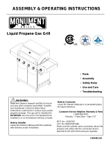
4. Refer to the figure below and perform one of
these 3 cleaning methods:
[] METHOD 1: Bend a stiff wire or wire coat
hanger into a small hook as shown and run
the hook through the Burner Tube and inside
the Burner several times to remove debris.
TO CLEAN BURNER TUBE,_
INSERT HOOK HERE
BureerTube
[] METHOD 2: Use a bottle brush with a flexible
handle and run the brush through the Burner
Tube and inside the Burner several times to
remove any debris.
[] METHOD 3: Use an air hose to force air
through each Burner Tube. The forced air
should pass debris or obstructions through
the Burner and out the Ports.
For safe operation ensure the Gas Valve Assem-
bly Orifice is inside the Burner Tube before
using your grill. See figure. If the Orifice is not
inside the Burner Tube, lighting the Burner may
cause explosion and/or fire resulting in serious
bodily injury and/or property damage.
Gas Valve AssembIy Orifice BurnerTube
LPG grill models must be used with Liquid
Propane Gas and the regulator assembly
supplied. Natural Gas models must be used
with Natural Gas only. Any attempt to convert the
grill from one fuel type to another is extremely
hazardous and will void the warranty.
• Never use your gas grill in a garage, porch, shed,
breezeway or any other enclosed area.
• Never obstruct the flow of ventilation air around
your gas grill housing.
Never disconnect the gas regulator or any gas
fitting while your grill is lit. A lit grill can ignite
leaking gas and cause a fire or explosion which
could result in property damage, personal injury
or death.
Keep gas regulator hose away from hot
grill surfaces and dripping grease. Avoid
unnecessary twisting of hose. Visually inspect
hose prior to each use for cuts, cracks,
excessive wear or other damage. If the hose
appears damaged do not use the gas grill. Call
Sears at 1-800-4-MY-HOME _ (1-800-469-4663)
for a Sears replacement hose.
PRE-ASSEMBLY
Read and perform the following pre-assembly instruc-
tions:
[] Tools Required for Assembly include:
• protective work gloves
• protective eyewear
• #3 Phillips Head Screwdriver
[] You will need assistance from another person to
handle the large, heaw parts.
[] Open Lid of shipping carton and remove parts box
and packing materials. Lay cardboard sheet on floor
and use as a work surface to protect floor and grill
parts from scratches.
[] Slice all four corners with a utility knife to lay open
the carton. This allows you to remove the compo-
nents packed inside.
[] Use the Hardware and Part Diagrams to ensure all
items are included and free of damage.
[] Do not assemble or operate the grill if it appears
damaged. If there are damaged or missing parts
when you unpack the shipping box or you have
questions during the assembly process, call the:
Grill Information Center 1- 888-317-7642
8am-8pm CST, Monday throu,qh Friday

PART #
P06001056A
S112G04081
$112G04081
$313G04081
$112G03061
Already Installed
PART DESCRI PTION
Hardware Pack
Phillips Head Screw 1/4"xl/2"
Phillips Head Screw 1/4"xl/2"
Flange Nut 1/4"
Phillips Head Screw 3/16"x3/8"
on the Cart Rear and Right
P05536001A Hose Holder
Already installed on the Cart Bottom Shelf
$233G05461 Wing Bolt 5/16"x4-1/2"
S303G0504D Special Nut 5/16"
QTY PURPOSE OF PART
1 For use in assemblyofLPG Model 16677
8 Attaches Side ShelfLeft to Bowl Side Panel
Attaches Side Burner Frame to Bowl Side Panel
4
2 Attaches Decorative Panel to Bowl Side Panel
Cart Side Panel
2 Attaches RegulatorAssemblyto Cart Rear Panel and Right
Cart Side Panel
1
Secures Gas Tank
1
©
Phillips Head Screw Flange Nut 1_"
1_" x 1/2" Qty. 4
Qty. 12 PaR# $3!3G04081
Part# $1!2G04081
F"
Already installed on the Cart Bottom Shelf
I/!/!/!/!/!/!/!/!/!/!/!/!/!/!1]
Wing Bolt 5/16"x4-1/2"
Qty. 1
Part. # S233G05461
Scale 1:2
Special Nut 5/16"
Qty. 1
Part. # S303G0504D
Scale 1:2
Already installed on the Cart Rear
and Right Side Panel
,__[ J Hose Holder
I Qty. 2
Part # P05536001A
• .L Scale 1:2
Phillips Head Screw 3/16"x3/8"
Qty. 2
Part # $1!2G03061
* Two Battery/AA included in the Hardware Pack.

4
5
1
2
10
G
B5__
80
79
\
76
13
8
12
B1
B4_ _
18 \ B2
15 % B9
19 _ BIO
26
28
33 \
77
24
20_
16
38
69
6
70

KEY DESCRIPTION PART # QTY
1 Lid P0014707MA 1
2 Temperature Gauge P00601071A 1
3 Lid Handle P00205068B 1
4 Protective Pad P055180021 4
5 Name Plate P00410039C 1
6 Cooking Rack/Secondary P01518004A 1
7 Cooking Grid P01604013B 2
8 Cooking Grid P01604010A 1
9 Cooking Grid P01615030F 1
10 Savor Plate® P01708007B 5
11 Burner/Main P02008032A 5
12 Grill Bowl P0071333ED 1
13 Grease Draining Plate P06902017C 2
14 Savor Plate® Bracket, Front P03328015A 5
15 Savor Plate® Bracket, Rear P03328017A 5
16 BurnerHeatShield P06906034C 1
17 GreaseTrayHeatShield P06901016C 1
18 Wind Shield, Rear P06906044C 1
19 Burner Bracket P0220509GA 1
Gas Valve/Manifold Assembly(LPG Only) Y0060410 1
20
Gas Valve/Manifold Assembly(NG Only) Y0060411 1
21 Gas Manifold P03708002C 1
22 Gas Manifold Connector P03715006D 1
23 Gas Collector Boxwith Electrode P02609009M 5
24 Electric Wire Set P02615101A 1
25 Electric Wire, 5-contact P02615102A 1
26 Control Panel, Upper P02911771S 1
Control Panel (LPG Only) P02911787S 1
27
Control Panel (NG Only) P02911797S 1
28 Electric Ignitor, 5-port P02502218C 1
29 Electric Ignitor, 2-port P02502172C 1
30 Electric Ignitor Protector, 5-port P03343007A 1
31 Electric Ignitor Protector, 2-port P03343006A 1
32 Control Knob For Main Burner P03428073H 5
33 Control Knob Seat P03413011J 7
Grease Tray (LPG Only) P02717234A 1
34
Grease Tray(NG Only) P02717244A 1
34A GreaseTrayHeatShield, Lower (LPG Only) P06901017C 1
35 Grease Tray Handle P0272003HC 1
36 Wheel for Grease Tray P05354002A 4
37 Regulator With Hose (LPG Only) P03601039A 1
38 Regulator (NG Only) P03628001B 1
39 Hose Holder (LPG Only) P05536001A 2
40 Hose, 12 ft. (NG Only) P03704001A 1
41 Extension Hose (NG only) P03705082F 1
42 Infrared Burner Assembly P02005010A 1
43 Therm ocouple Bracket P03327035A 1
44 Infrared Burner Electrode P02618007M 1
45 Infrared Burner Thermocouple P05305018A 1
46 Bowl Support Bracket, Left PO1301010B 1

KEY DESCRIPTION PART# QTY
47 BowlSupportBracket,Right P01302010B 1
CartBottomShelf(LPGOnly) PO102OOO2A 1
48
CartBottomShelf(NGOnly) PO102OOO3A 1
49 CartSidePanel,Left P07614010A 1
CartSidePanel,Right(LPGOnly) PO761502OA 1
50
CartSidePanel,Right(NGOnly) PO7615021A 1
51 CartPartitionPanel,Left P07512008N 1
52 CartPartitionPaneI,Right(NGOnly) P07512009N 1
53 CartBottomPanelBracket,LF/RR P03328024C 2
54 CartBottomPanelBracket,RF/LR P03328046C 2
55 CartRearPanel P07701070A 1
56 Caster2-1/2in. P05117010A 2
57 Caster2-1/2in.,withBrake P05110007A 2
58 CasterSeat,LF P05327009Q 1
59 CasterSeat,RF P05327011Q 1
60 CasterSeat,LR P05327010Q 1
61 CasterSeat,RR P05327012Q 1
62 Door,Left PO430204OA 1
63 Door,Right P04303040A 1
64 DoorHandle P00205073B 2
65 DoorHingeBracket,UpperLeft P03314041C 1
66 DoorHingeBracket,UpperRight P03314049C 1
67 CartBracket P03306028A 1
68 Weight P05344004Q 1
69 Handle/Drawer P00212003A 2
70 Drawer Y0420009 2
71 CartPartitionPanelBracket,FrontLeft P019070101 1
72 CartPartitionPanelBracket,FrontRight P01907009B 1
73 CartPartitionPanelBracket,Rear P019070111 2
74 DoorMagnet P05523005M 4
75 DrawerSlideSet P01907006B 4
76 SideShelf,Left P01106009B 1
77 DecorativePanelforSideShelf P07503007A 1
78 LightingStick P05507031E 1
79 ToolHolder P05209004B 1
80 TooIHooks PO5514131F 4
81 ControlKnobForInfraredBurner P03428073H 1
A1 SideBurnerFrame P01108013B 1
A2 DecorativePanelforSideBurnerFrame P07502017A 1
A3 SideBurnerBody P02301019B 1
A4 SideBurnerLid P01127007B 1
SideBurnerwithBrassRing(LPOnly) P02002007A 1
A5
SideBurnerwithBrassRing(NGOnly) P02002014A 1
A6 SideBurnerPotSupport P00805010A 1
A7 SideBurnerElectrode P02614014C 1
A8 SideBurnerGasValve Y0060399 1
A9 SideBurnerControIKnob P03401013H 1
A10 SideBurnerControlKnobSeat P03408053S 1
A11 SideBurnerConnectionHose,Plug P037050511 1
A12 SideBurnerConnectionHose,Bracket P03341001C 2
A13 SideBurnerBracket P03327037C 1

KEY DESCRIPTION PART# QTY
B1 BackBurnerAssembly P02007067A 1
BackBurnerOrifice(LPGOnly) P06527003A 1
B2
BackBurnerOrifice(NGOnly) P06527004A 1
B3 BackBurnerExtensionTube P03717044B 1
B4 BackBurnerElectrodeAssembly P02610005B 1
B5 BackBurnerWindShield P06905046B 1
B6 BackBurnerFrame P02007015D 1
B7 BackBurnerWindShield,Front P06905050C 1
B8 ControlKnobForBackBurner P03411423Y 1
B9 BackBurnerThermocouple P05305021A 1
B10 BackBurnerThermocoupleBracket P03328047C 1
RotisserieAssembly Y0250119 1
HardwarePack P06001056A 1
Operator'sManual P80106006P 1
Fortherepairorreplacementpartsyouneed:
anytime1-800-4-MY-HOME® (1-800-469-4663)
To obtain the correct replacement parts for your gas grill, please refer to the part numbers in this parts
list. The following information is required to ensure you receive the correct parts:
1. Model and Serial Number (see CSA label on grill)
2. Part Number
3. Part Description
4. Quantity of parts needed
Important: Use only Sears replacement parts. The use of any part that is not a Sears replacement part
can be dangerous and will also void your product warranty. Keep this Operator's Manual for
convenient referral and for part replacement.

7
6
3
5
7
KEY DESCRIPTION
PART# QTY
1. Rot. Motor Bracket
2. Rot. Screw #10-24x3/4" UNC
3. Rot. Hex Nut #10-24
4. Rot. Washer 3/16"
5. Rot. Spit
6. Rot. Holding Fork
7. Rot. Thumbscrew 3/8"x1/2"
8. Rot. Collar
9. Rot. Bushing
10. Rot. Motor/AC
P03307003A
S112G10121
S362G10121
S411G03081
P05508170A
P05508169A
S196G06081
P05508168A
P05508167A
P07101025A
1
2
2
2
1
2
3
1
1
1
_IIIIIIIIIIIIIIIIII]
©
Rot. Thumbscrew
3/8"xl/2"
Qty. 3
Part# $196G06081
Rot. Screw#10-24x3/4"
UNC
Qty. 2
Part# $1!2G10121
Rot. Washer 3/16"
Qty. 2
Part# $411G03081
Rot. Hex Nut#10-24
Qty. 2
Part# S362G10121

Install Left Side Shelf and Right Side Burner Frame
[] Place the Side Shelf over the Left Side Shelf Brackets and Side Burner Frame over the
Right Side Shelf Brackets.
[] Tighten securely by using Screws and Nuts provided.
[] Secure Decorative Panel to Bowl Side Panel using Phillips Head Screw 3/16"x3/8".
[] Remove 2 M4xl0mm screws from the Tool Holder. Slide the 4 Tool Hooks onto
the Tool Holder with the hooks facing the Left Side Shelf. Attach Tool Holder to
Side Shelf using these screws.
[] From the front of the grill, slide the assembled Tray side tabs over the side rails
underneath the Grill Bowl.
Phillips Head Screw
1/4" x 1/2"
Qty. 12
Part# $112G04081
©
Flange Nut 1/4"
Qty. 4
Part# $3!3G04081
Decorative Panel
Grease Tray
\
Phillips Head Screw 3/16"x3/8"
Qty. 2
Part # $1!2G03061
Install Side Burner Connection Hose
[] Push back Sleeve of the Socket. See Figure A.
insert Plug then release Sleeve. See Figure B.
Push Plug until sleeve snaps forward locking the
Plug into the Socket. See Figure C.
[] Push the Side Burner Hose into hose holder.
Hose Holders
Decorative Panel
Figure A
PLUG
Figure B
Figure C
SOCKET
SLEEVE
_\SLEEVE
Plug
10

Install Ignitor Batteries
[] Unscrew Ignitor Cap from Control Panel.
[] Place supplied AA batteries into the
ignitor Slots with positive pole facing
you.
[] Position the Caps and Springs over the
AA batteries and tighten onto Control
Panel.
Main Burners Electrode Check
Perform this Electrode Check with the
assistance of another person.
This test will ensure that the Spark Electrode Tips
are properly positioned so your grill lights easily
and properly.
Spring
H nstall Cooking Components
[] Place the Savor Plates ® on lower ledge
above Burners.
[] Place Cooking Grids on bowl ledge.
[] Place the Secondary Cooking Rack into
the slots on Grill Bowl Side Panels
Spark Receiver Spark Eiectrode Tip
[] Be sure all Control Knobs are set to
"OFF" and open the Grill Lid.
[] Have your assistant stand behind to the
right of the grill and look toward the front
of the grill bowl. Never put your face
inside the Grill Bowl.
[] Press the Ignitor Cap. You should hear
a "clicking" sound. Your assistant should
see a blue spark within each Gas
Collector Box. If a spark is present the
Electrode Tips are properly positioned.
[] If no spark is seen, the Spark Gap
needs to be adjusted as follows:
• Using an adjustable wrench, loosen the
inside Nut until the Gas Collector Box can
be turned upward.
• If the gap between the Spark Elec-
trode Tip and Receiver is more than
3/16" use long nose pliers to gently
squeeze the Gas Collector Box to
narrow gap.
• Return the Gas Collector Box to its
original position, secure the inside Nut
and try the Electrode Check again. If no
"clicking" sound is heard:
• AA Batteries may be installed back-
wards.
• Electric wires may be loose. Remove
the AA Batteries and inspect the
ignitor Junction Box found behind the
Control Panel and reconnect any
loose wires.
Side Burner Electrode Check
[] Open side burner lid. Remove plastic
shipping band from burner and pot
support.
[] Push and turn side burner Control Knob
to HIGH. Look for spark between tip of
electrode and burner.
[] If you don't see a spark from side burner elec-
trode, adjust gap between electrode and
burner surface to 3/16 in.
Secondary Cooking
Cookir
Slots for
Secondary
Cooking Rack
Savor Plates ®
When you have finished assembling your
grill be sure that all screws are tightened
for safe operation of your grill.
Failure to read and follow the Use and Care
Instructions could result in a fire or explosion
that could cause serious bodily injury, death or
property damage.
11

CORRECT LP GAS TANK USE
[] LP Gas grill models are designed for use with a
standard 20 lb. Liquid Propane Gas (LP Gas) tank,
not included with gdll. Never connect your gas grill to
an LP Gas tank that exceeds this capacity. A tank of
approximately 12 inches in diameter by 18-1/2 inches
high is the maximum size LP Gas tank to use. You
must use an "OPD" gas tank which offers a listed
Overfill Prevention Device. This safety feature
prevents tank from being overfilled which can cause
malfunction of LP Gas tank, regulator and/or grill.
[] The LP Gas tank must be constructed and marked in
accordance with the Specifications for LP-Gas Cylin-
ders of the U.S. Department of Transportation (D.O.T.)
or the National Standard of Canada, CAN/CSA-B339,
Cylinders, Spheres and Tubes for Transportation of
Dangerous Goods; and Commission, as applicable.
[] The LP Gas tank must have a shutoff valve, terminat-
ing in an LP Gas supply tank valve outlet, that is
compatible with a Type 1 tank connection device. The
LP Gas tank must also have a safety relief device
that has a direct connection with the vapor space of
the tank.
[] The tank supply system must be arranged for vapor
withdrawal.
[] The LP Gas tank used must have a collar
to protect the tank valve.
[] Never connect an unregulated LP gas tank to your
gas grill. The gas regulator assembly supplied with
your gas grill is adjusted to have an outlet pressure
of 11" water column (W.C.) for connection to an LP
gas tank. Only use the regulator and hose assembly
supplied with your gas grill. Replacement regulators
and hose assemblies must be those specified by
Sears. See Parts List.
[] Have your LP Gas dealer check the release valve
after every filling to ensure it remains free of defects.
[] Always keep LP Gas tank in upright position.
[] Do not subject the LP Gas tank to excessive heat.
[] Never store an LP Gas tank indoors. If you store
your gas grill in the garage always disconnect the
LP Gas tank first and store it safely outside.
[] LP Gas tanks must be stored outdoors in a well-
ventilated area and out of the reach of children.
[] Disconnected LP Gas tanks must not be stored in a
building, garage or any other enclosed area.
[] The regulator and hose assembly can be seen after
opening the doors (if applicable) and must be
inspected before each use of the grill. If there is
excessive abrasion or wear or if the hose is cut, it
must be replaced prior to using the grill again.
[] Never light your gas grill with the lid closed or
before checking to ensure the burner tubes are fully
seated over the gas valve orifices.
[] Never allow children to operate your grill. Do not
allow children or pets to play near your grill.
[] Use of alcohol or drugs may impair the ability to
assemble and operate the appliance.
[] Keep fire extinguisher readily accessible. In the
event of a oil/grease fire, do not attempt to
extinguish with water. Use type B extinguisher
or smother with dirt, sand or baking soda.
[] In the event of rain, cover the grill and turn off
the burner and gas supply.
[] Use your grill on a level, stable surface in an
area clear of combustible materials.
[] Do not leave grill unattended when in use.
[] Do not move the appliance when in use.
[] Allow the grill to cool before moving or storing.
[] Do not use your grill as a heater.
[] This grill is not intended to be installed in or on
recreational vehicles and/or boats.
[] Never use charcoal in this gas grill.
A. Do not store a spare LP-Gas tank under or near
this appliance.
B. Never fill the tank beyond 80 percent full; and
C. If the information in "(a)" and "(b)" is not followed
exactly, a fire causing death or serious injury may
occur.
• Use your grill at least 3 feet away from any
wall or surface. Use your grill at least 3 feet
away from combustible objects that can melt
or catch fire (such as vinyl or wood siding,
fences and overhangs) or sources of ignition
including pilot lights on water heaters and live
electrical appliances.
• Outdoor cooking gas appliance shall not be
used under overhead combustible construction.
• Never use your gas grill in a garage, porch, shed,
breezeway or any other enclosed area.
• Never obstruct the flow of ventilation air around
your gas grill housing.
12

NOTE about LP Gas Tank Exchange Programs
• Many retailers that sell grills offer you the option of
replacing your empty LP Gas tank through an ex-
change service. Use only those reputable exchange
companies that inspect, precision fill, test and certify
their tanks. Exchange your tank only for an OPD safety
feature-equipped tank as described in the LP Gas tank
section of this manual.
• Always keep new and exchanged LP Gas tanks in an
upright position during use, transit or storage.
• Leak test new and exchanged LP Gas tanks BEFORE
connecting one to your grill.
How to Leak Test your LP Gas Tank
For your safety:
• All leak tests must be repeated each time your LP
Gas tank is exchanged or refilled.
• When checking for gas leaks do not smoke.
• Do not use an open flame to check for gas leaks.
• Your grill must be leak tested outdoors in a well-
ventilated area, away from ignition sources such as
gas fired or electrical appliances. During the leak test,
keep your grill away from open flames or sparks.
• Do not use household cleaning agents. Damage to
gas assembly components can result.
[] Use a clean paintbrush and a 50/50 mild soap and
water solution.
[] Brush soapy solution onto LP Gas tank in the
areas indicated by the arrows. See diagram.
[] If growing bubbles appear do not use or move the
LP Gas tank. Call an LP Gas Supplier or your Fire
Department.
4-
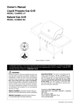
To Install LP Gas Tank (LPG model only):
Secure a 201b LP Gas Tank to Gas Grill
[] Screw the Wing Bolt and Special Nut to Cart
Bottom Shelf.
[] Turn your LP Gas Tank Valve clockwise to the
closed or OFF positon.
[] Place LP Gas tank into tank hole on bottom shelf
or (on select models) slide the Tank Tray out of
the cabinet until it is fully extended. The Tank Tray
has an auto lock position and may need to be
pulled firmly.
[] install the tank so the Tank Valve faces the front
right corner of cabinet.
[] Secure Gas Tank with Special Nut and Wing Bolt.
The Special Nut has
to be mounted to the
Wing Bolt BEFORE
inserting tank into
tank hole.
With the Special Nut,
the Wing Bolt holds
the tank foot firmly.
[I!t!t//!Iflt/t/!N///!/!/!/!/A
Special Nut 5/16" Wing Bolt 5/16"x4-1/2"
Qty. 1 Qty. 1
Part. # S303GO504D Part. # $233G05461
Scale 1:2 Scale 1:2
If growing bubbles appear do not use or move
the LP Gas tank. Contact an LP Gas Supplier
or your fire department!
NOTE: Many different size propane gas tank bottom
collars are available in the market, especially with the
popularity of tank exchange programs, tf your tank
bottom collar does notfit into the tank hole after attaching
the special nut tothe wing bolt, simply remove the special
nut and secure the tank using the wing bolt only.
13

LP Gas Model only:
Connect Regulator with Hose to your LP Gas Tank
[] Turn all Burner Valves to the OFF position.
[] Inspect the valve connection port and regulator
assembly for damage or debris. Remove any
debris. Never use damaged or plugged equip-
ment.
[] Connect the regulator assembly to the tank valve
and HAND TIGHTEN nut clockwise to a full stop.
DO NOT use a wrench to tighten because it could
damage the Quick Coupling Nut and result in a
hazardous condition.
[] Open the tank valve 1/4 to 1/2 (counterclockwise)
and use a soapy water solution to check all
connections for leaks before attempting to light
your grill. See "Checking for LP Gas Leaks". If
a leak is found, turn the tank valve off and do not
use your grill until the leak is repaired.
TyPsl 12_n5zatt_°coZer
Quick
Coupling Nut
CAUTION: When the appliance is not in use the gas
must be turned off at the tank.
Check all connections for LP Gas Leaks
Never test for leaks with a flame. Prior to first use,
at the beginning of each season, or every time
your LP Gas tank is changed, you must check for
gas leaks. Follow these three steps:
[] Make a soap solution by mixing one part liquid
detergent and one part water.
[] Turn the grill Control Knobs to the full OFF
position, then turn the gas ON at source.
[] Apply the soap solution to all gas connections
indicated by the arrows. See diagram. If
bubbles appear in the soap solution the
connections are not properly sealed. Check
each fitting and tighten or repair as necessary.
Manifold Assembly
I
I
LP Gas Tank
If you have a gas leak that cannot be repaired
by tightening, turn off the gas at the source,
disconnect fuel line from your grill and call
1-800-4-MY-HOME ° or your gas supplier for
repair assistance.
Disconnecting A Liquid Propane Gas (LPG)
Tank From Your Grill
[] Make sure the Burner Valves and LP Gas tank
valve are off. (Turn clockwise to close.)
[] Detach the hose and regulator assembly from
the LP Gas tank valve by turning the Quick
Coupling Nut counterclockwise.
14

Natural Gas Model only:
Connecting Natural Gas To Your Grill
[] Connect the Swivel nut of the 12' Natural Gas
Hose to the vertical fitting of NG Regulator as
shown in Fig. 1. Connect the other hose end
(male plug) to the gas supply line from house.
Also, read and follow all natural gas safety
instructions below.
Natural Gas Safety Instructions
[] Your natural gas grill is designed to operate on
natural gas only, at a pressure of 4" water column
(W.C.) with natural gas regulator. The gas pres-
sure Regulator supplied with this appliance must
be used. This Regulator is set for an outlet
pressure of 4" W.C.
[] Install a Shutoff Valve at the gas supply source
outdoors at a point after the gas pipe exits the
outside wall and before the quick-disconnect
hose. Or install it at the point before the gas line
piping enters the ground. See Fig. 2.
[] Pipe sealing compound or pipe thread tape
resistant to the action of natural gas must be used
on all male pipe thread connections.
[] Disconnect your gas grill from fuel source when
the gas supply is being tested at high pressures.
This gas grill and its individual shutoff valve must
be disconnected from the gas supply pipe system
during any pressure testing of that system at
pressure in excess of 1/2 psi (3.5kpa).
[] Turn off your gas grill when the gas supply is
being tested at low pressures. The grill must be
isolated from the gas supply pipe system by
closing its individual manual shutoff valve during
any pressure testing of the gas supply pipe
system at pressures equal to or less than 1/2 psi
(3.5kpa).
Figure 1 S
Vertical fitting _ _ __
Swwel nut _
Check all connections for NG Leaks
Never test for leaks with a flame. Prior to first use,
at the beginning of each season, you must check
for gas leaks. Follow these three steps:
[] Make a soap solution by mixing one part liquid
detergent and one part water.
[] Turn the grill Control Knobs to the full OFF
position, then turn the gas ON at source.
[] Apply the soap solution to all gas connections
indicated by the arrows. See Fig. 3. If bubbles
appear in the soap solution the connections are
not properly sealed. Check each fitting and
tighten or repair as necessary.
Figure 3
Gas Valve / Manifold Assembly
/
Figure 2
NG Regulator J
Inside Wall
Gas
Hose, 12 ft./NG
Outside Wall
Male Fitting
Shut Off
Locking
Shut Off
Quick
Disconnect
If you have a gas leak that cannot be repaired
by tightening, turn off the gas at the source,
disconnect fuel line from your grill and call
1-800-4-MY-HOME ® or your gas supplier for
repair assistance.
15

Grill Lighting Instructions
1. Before each use, check all hoses for cracks, nicks, cuts,
burns or abrasions, if a hose is damaged in any way, do
not use your grill before replacing the hose with an
authorized part from the Parts List. Also make sure all
gas supply connections are securely tightened.
2. Familiarize yourself with the safety and Use and Care
instructions in this manual. Do not smoke while lighting
grill or checking gas supply connections.
3. Be sure the LP Gas tank is filled.
4. Open the Grill Lid.
5. Check that the end of each Burner Tube is properly
located over each Valve Orifice.
Failure to replace a faulty hose, secure gas supply
connections or to open the Lid before proceeding
to the Lighting Procedures could result in a fire
or explosion that could cause serious bodily injury,
death, or property damage.
6. Set Control Knobs to OFF and open the LP Gas
tank valve SLOWLY 1/4 of a turn. For Natural Gas
open the Shut Off Valve at source.
| Open LP Gas tank _-"_
OFF
7. Push and turn one Control Knob to IGN and hold it in
3-4 secs to ignite the Burner._Once the burner is lit,
turn the knob back to HIGH,
!
IGN
Low_
OFF
8. If ignition does not occur in 5 seconds, turn gas off at
source and turn Control Knobs OFF. Wait at least 5
minutes for gas to clear, then retry. If your grill still fails
to light turn the burner Control Knob(s) and gas source
OFF and conduct a leak test of ALL gas connections
and gas sources as explained in the Use and Care
section of this manual, if no leaks are detected, wait 5
minutes for any gas to clear and repeat the lighting
procedure.
9. After one Burner is lit, turn the tank valve SLOWLY one
more 1/4 of a turn for 1/2 of one complete turn.
10. Repeat steps to light each burner individually. Turn
Knob for each other burner and light as you move
toward the fuel source.
Burner Control Knobs on Control Panel
Main Burner Back Infrared
Burner Burner
16
Back Burner Lighting Instructions
1. Follow steps 1 through 6 of the Grill Lighting
instructions.
2. Push and turn the Control Knob to IGN and hold it in
3-4 seconds to ignite the Burner.
3. Keep pressing and turning knob to HIGH and hold in
5-10 seconds before releasing.
4. if ignition does not occur in 5 seconds, turn gas off
at source and turn Control Knobs OFF. Wait at least
5 minutes for gas to clear, then retry. If your grill still
fails to light turn the Control Knob(s) and gas
source OFF and conduct a leak test as explained in
the Use and Care section of this manual. If no
leaks are detected, wait 5 minutes for any gas to
clear and repeat the lighting procedure.
5. After Burner is lit, turn the tank valve SLOWLY one
more 1/4 of a turn for 1/2 of one complete turn.
IMPORTANT: Do not use the Back Burner and Main
Burners at the same time. Backburner is for Rotisserie
Cooking only.
BACK BURNER KNOB:
!
IGN
OFF
Infrared Burner Lighting
1.
2.
3.
4.
INFRARED BURNER
KNOB: |
IGN
Low_
OFF
Instructions
Follow steps 1 through 6 of the Grill Lighting
instructions.
Push and turn the Control Knob to IGN and hold it in
3-4 secs to ignite the Burner.
Keep pressing and turning knob to HIGH and hold in
5-10 seconds before releasing.
if ignition does not occur in 5 seconds, turn the
burner Control Knob(s) and gas source OFF and
conduct a leak test as explained in the Use and
Care section of this manual. If no leaks are de-
tected, wait 5 minutes for any gas to clear and
repeat the lighting procedure.
5. After Burner is lit, turn the tank valve SLOWLY one
more 1/4 of a turn for 1/2 of one complete turn.
Side Burner Lighting Instructions
1. Follow steps 1 through 5 of the Grill Lighting
Instructions.
2. Open Side Burner Lid.
3. Set Control Knobs to OFF and open the LP Gas
tank valve SLOWLY 1/4 of a turn.
4. Push and turn control knob to HIGH ._
5. You may have to push and turn the Control Knob up
to 3 or 4 times to light.
6. If ignition does not occur, turn gas off at source and
turn Control Knobs OFF. Wait at least 5 minutes for
gas to clear, then retry, if your grill still fails to light turn
the burner Control Knob and gas source OFF and
conduct a leak test of ALL gas connections and fuel
sources. If no leaks are detected, wait 5 minutes for
any gas to clear and repeat the lighting procedure.
Manually Lighting Your Grill By Paper Match
To light your gas grill by match, insert a match into the
Lighting Stick and follow steps 1 through 6 of the Grill
Lighting Instructions. Then, light the match and place
(continue over page)

LightingStickthroughtheLightingHoleontheleftside
ofthegrillasshownbelow.TurnthenearestControl
KnobtotheHIGHsettingtoreleasegas.TheBurner
shouldlightimmediately.
LightingH_
[]
[]
[]
Disconnected Electric Wires
Correction: inspect the Electric ignitor (see Parts
List) found behind the Control Panel. Connect loose
Electric wires to Junction Box and try to light the grill.
Weak AA battery
Correction: Unscrew the Ignitor Cap and replace
the battery.
If the grill still does not light you may need to
purge air from the gas line or reset the
regulator excess gas flow device. Note: This
procedure should be done every time a new
LP Gas tank is connected to your grill.
Lighting
Match
Troubleshooting
If the grill fails to light :
2.
3.
[]
[]
[]
[]
[]
Turn gas off at source and turn Control Knobs to
OFF. Wait at least 5 minutes for gas to clear, then
retry.
If your grill still fails to light, check gas supply
and connections.
Repeat lighting procedure. If your grill still fails
to operate, turn the gas off at source, turn the
Control Knobs to OFF, then check the following:
Misalignment of Burner Tubes over Orifices
Correction: Reposition Burner Tubes over Orifices.
Obstruction in gas line
Correction: Remove fuel line from grill. Do not
smoke! Open gas supply for one second to clear
any obstruction from fuel line. Close off gas supply
at source and reconnect fuel line to grill.
Plugged Orifice
Correction: Remove Burners from grill by remov-
ing the screw from the rear of each Burner using a
Phillips Head Screwdriver. Carefully lift each
Burner up and away from gas valve Orifice.
Remove the Orifice from gas valve and gently clear
any obstruction with a fine wire. Then reinstall all
Orifices, Burners and cooking components.
If an obstruction is suspected in Gas Valves or
Manifold, call the Grill Information Center.
Obstruction in Burner Tubes
Correction: Follow the Burner Tube cleaning
procedure on page 22 of this Operator's Manual.
Misalignment of Ignitor on Burner
Correction: Check for proper position of the
Electrode Tip as shown in step 4 page 11. The
gap between the Spark Electrode Tip and Spark
Receiver should be approximately 3/16". Adjust
if necessary. With the gas supply closed and all
Control Knobs set to OFF press the Electric
Ignitor cap and check for the presence of a spark
at the Electrode.
To purge air from your gas line and/or reset
the regulator excess gas flow device:
[] Turn Control Knobs to the OFF position.
[] Turn off the gas at the tank valve.
For Natural Gas shut off NG valve.
[] Disconnect regulator from LP Gas tank.
For Natural Gas disconnect regulator from 12 ft.
Natural Gas Hose.
[]
[]
Let unit stand 5 minutes to allow air to purge
from gas line.
Reconnect regulator to the LP Gas tank.
For Natural Gas reconnect regulator to 12 ft.
Natural Gas Hose.
[] Turn tank valve on SLOWLY 1/4 of a turn.
For Natural Gas open Shut Off valve.
[] Open the Grill Lid.
[] Push and turn the LEFT Control Knob to HIGH.
[] Press Electric ignitor for 3-4 seconds to light
the burners.
Should a FLASHBACK fire occur in or around
the Burner Tubes, follow the instructions below.
Failure to comply with these instructions could
result in a fire or explosion that could cause
serious bodily injury, death, or property damage.
• Shut off gas supply to the gas grill.
• Turn the Control Knobs to OFF position.
• Open the Grill Lid.
• Put out any flame with a Class B fire
extinguisher.
• Once the grill has cooled down, clean
the Burner Tubes and Burners according
to the cleaning instructions in this
Operator's Manual.
GRILL INFORMATION CENTER
Call 8am to 8pm CST 1-888-317-7642 Monday through Friday
17

Never lean over the grill cooking area while
lighting your gas grill. Keep your face and body
a safe distance (at least 18 inches) from the
Lighting Hole or Burners when lighting your grill
by match.
Keep any electrical supply cord and the fuel
supply hose away from any heated surface.
CORRECT ROTISSERIE USE
1. Read all instructions before initial use.
IMPORTANT: When using electrical appliances, basic
safety precautions should always be used.
The Rotisserie Motor is set for 120V, 60Hz AC current.
The Rotisserie is for outdoor use only.
Do not let children operate or play nearby your grill or
Rotisserie.
Connecting Rotisserie
2. Always attach the assembled Rotisserie to your grill first
and then plug the Cord into an outlet.
Operating Rotisserie
3. Do not operate the Rotisserie if the cord or plug be-
comes damaged, or if the Rotisserie malfunctions or
has been damaged in any manner.
The use of accessory attachments is not recommeded
by the manufacturer and may cause injuries. Do not use
this Rotisserie other than for its intended use.
Do not immerse Electrical Cord, Plug or Motor in water
or expose to rain, as this may result in an electrical
shock.
Disconnect Rotisserie
Be careful as all surfaces will be hot, both grill and
Rotisserie parts. Use protective mitts to handle the
Rotisserie.
Unplug the Rotisserie from electrical outlet when not in
use and before cleaning. Allow to cool before adding or
removing parts.
When Roitsserie cooking place a Cooking Pan under
the food to be cooked as this will capture the drippings
and keep your grill clean of excess grease which could
cause a fire.
CAUTION: Handle with care when moving a Cooking
Pan with hot oils
Should a grease fire occur, turn the burners and gas off
and leave the grill lid Closed until the fire is out.
Store the Rotisserie indoors
5. When Rotisserie is not in use, store it indoors in a dry
place.
18

.
2.
Remove all components from the carton.
Attach the Motor Bracket on the outside of the left grill bowl panel. Align the two holes of the Bracket
with the holes on the grill bowl. Tighten securely using two Screws #10-24x3/4" UNC, Plain Washers
and Nuts provided.
Washer
#10-24 Nut
[ 111111111111111111/
Rot. Screw #10-24x3/4" UNC x2
©
Rot. Washer x2
Motor Bracket ._
Rot. Nut #10-24 x2
/(_, J'f'J
Rot. Screw#10-24x3/4"
UNC with washers
and nuts
Outside of left grill
bowl panel
.
Slide the Spit through the piece of meat or poultry and the Holding Forks onto each end of the Rotisserie
Spit. Adjust spacing between Holding Forks to accommodate your food, then tighten the Thumbscrews
to keep the Holding Forks in position. Slide the Collar and Bushing onto the threaded end of the Spit.
Do not tighten the Collar Thumbscrew until the Rotisserie is placed into your grill.
Thumbscrew
3/8"xl/2"
Rot.Thumbscrew 3/8"xl/2" x3
Holding Forks
Spit
Bushing
Collar
Thumbscrew
3/8"x1/2"
19

4. InstalltheAC(alternatingcurrent)RotisserieMotorontotheMotorBracketasshownbelow.Besure
theMotorattachesto the Bracketwiththe electricalcorddown.This installationinsuresthatonce
the Spitis insertedinto the Motorit will alsorestsecurelyintotheslotof yourgrillbowl.
Rotisserie Motor
Motor Bracket
.
Rotisserie Spit must rest securely
into the slot of your grill bowl.
Insert the assembled Rotisserie into the Motor as shown below. The Motor should be on the left side
of your grill. Place the Bushing into the slot opening on the right side of your grill bowl, then tighten
the Collar Thumbscrew to the right of the Bushing. The Collar will stabilize the Rotisserie during the
cooking process and the Bushing allows the Rotisserie Spit to turn smoothly. Plug the Rotisserie into
an outlet and turn on to test.
Motor
Thumbscrew Holding Forks Thumbscrew
Bushing
z
Spit
Collar
The Bushinq and Collar must always be used with this Rotisserie.
BEFORE rotisserie cooking you will need to remove the Cooking Grid(s) and possibly the Savor Plates ®
from your grill. When rotisserie cooking place a Cooking Pan under the food to be cooked. This will
capture the drippings and keep your grill clean of excess grease which could cause a fire. Use caution
when moving a Cooking Pan containing hot oils.
20
/