
UK
Brine/Water Heat Pumps
Professional
Operating Manual
SWP – Series
83050900dUK – Translation into English of the original German operating manual

2
Subject to change without notice | 83050900dUK – Translation into English of the original German operating manual | ait-deutschland GmbH
Please read rst
These operating instructions provide information on
how to use the appliance. They are an integral element
of the product and must be kept within easy reach in
close proximity to the appliance. They must remain
available throughout the entire service life of the appli-
ance. They must be handed over to new owners or us-
ers of the machine.
Read the operating instructions before commencing all
work on and with the appliance. In particular, the Safe-
ty section. Follow all instructions to a full and unrestrict-
ed extent.
These operating instructions may contain descriptions
which appear unintelligible or unclear. If questions or un-
clear points arise, please contact the works customer
service or the local representative of the manufacturer.
As these operating instructions have been written for
several device types, you must always adhere to the pa-
rameters applicable for the relevant device type.
The operating instructions are only intended for persons
working on or with the appliance. Treat all elements in
condence. They are protected by copyright. They may
not be reproduced in any form, transferred, duplicated,
saved in electronic systems or translated into another
language, either in whole or in part, without the written
consent of the manufacturer.
Symbols
Symbols are used in the operating instructions. They
have the following signicance:
Information for uers.
Information or instructions for qualied
technicians.
DANGER!
Indicates a directly imminent hazard,
which will result in serious injuries or
death.
WARNING!
Indicates a potentially hazardous situa-
tion, which could result in serious injuries
or death.
CAUTION!
Indicates a potentially hazardous situa-
tion, which could result in moderate or
minor injuries.
AT TE NTIO N.
Indicates a potentially hazardous situation which
could result in material damage.
NOTE.
Emphasised information.
€
ENERGY SAVING TIP
Indicates suggestions that help to save energy,
raw materials and costs.
Reference to other sections in the operating in-
structions.
Reference to other help tips by the manufac-
turer.

3
Subject to change without notice | 83050900dUK – Translation into English of the original German operating manual | ait-deutschland GmbH
Table of Contents
INFORMATION FOR USERS AND QUALIFIED
PERSONNEL
PLEASE READ FIRST ..................................................................2
SYMBOLS .....................................................................................2
INTENDED USE .......................................................................... 4
EXCLUSION OF LIABILITY ...................................................... 4
EC CONFORMITY .....................................................................4
SAFETY .........................................................................................4
CUSTOMER SERVICE ................................................................5
WARRANTY / GUARANTEE ...................................................5
DISPOSAL ....................................................................................5
HOW HEAT PUMPS FUNCTION ............................................5
AREA OF APPLICATION ..........................................................5
HEAT QUANTITY RECORDING ............................................6
OPER ATION ................................................................................ 6
CARE OF THE DEVICE .............................................................6
DEVICE MAINTENANCE ..........................................................6
Cleaning and Rinsing of device components ....................6
FAULTS .........................................................................................7
INSTRUCTIONS FOR QUALIFIED TECHNICIANS
SCOPE OF SUPPLY ..................................................................... 7
SET-UP AND INSTALLATION .................................................8
Installation area ..................................................................... 8
Transport to the installation site .......................................8
Installation ..............................................................................9
ASSEMBLY OF THE HYDRAULIC CONNECTIONS .........10
RINSING, FILLING AND VENTILATING THE SYSTEM ...12
Rinsing, filling and bleeding the heat source ..................12
flushing and filling the heating circuit ..............................13
Water quality ....................................................................... 13
ISOLATION OF THE HYDRAULIC CONNECTIONS ......14
INSTALLATION OF THE CONTROL ELEMENT ...............15
INSTALLATION AND REMOVAL OF THE SCREEN .........16
BUFFER TANK...........................................................................17
CIRCULATION PUMPS ...........................................................17
DOMESTIC HOT WATER PREPARATION ..........................18
DOMESTIC HOT WATER TANK ..........................................18
COMMISSIONING ...................................................................18
DEIN STALL ATION ................................................................... 19
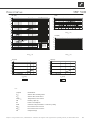
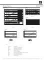
TECHNICAL DATA/SCOPE OF SUPPLY
SWP 1100 – SWP 1600 ......................................................20
SWP 700H – SWP 1000H .................................................22
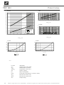
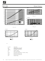
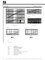
POWER CURVES
Heating Power/COP / Power Consumption /
Heat Pump Pressure Loss
SW P 110 0 .............................................................................24
SWP 1250 .............................................................................25
SWP 1600 .............................................................................26
SWP 700H ..........................................................................27
SWP 850H ............................................................................28
SWP 1000H .........................................................................29
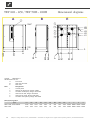
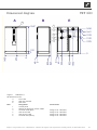
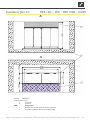
DIMENSIONAL DIAGRAMS AND
INSTALLATIONS PLANS
Dimensional diagrams
SWP 1100 – 1250 / SWP 700H – 1000H ........................30
SWP 1600 ............................................................................. 31
Installation plans .................................................................32
HYDRAULIC INTEGRATION
Separate buffer tank ...........................................................34
Legend Hydraulic integration ............................................35
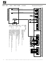
TERMINAL DIAGRAM .............................................................36
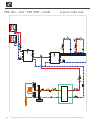
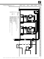
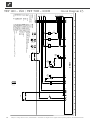
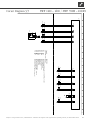
CIRCUIT DIAGRAMS ..............................................................37
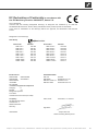
EC DECLARATION OF CONFORMITY ..............................41
TECHNICAL DATA ACCORDING ECODESIGN
DIRECTIVE
SW P 110 0 .............................................................................42
SWP 1250 ............................................................................ 44
SWP 1600 .............................................................................46
SWP 850H ............................................................................48
SWP 1000H .........................................................................50

4
Subject to change without notice | 83050900dUK – Translation into English of the original German operating manual | ait-deutschland GmbH
Intended use
The device must only be used in accordance with its in-
tended application. This is:
•
for heating.
•
for domestic hot water preparation.
The device may only be operated within its technical pa-
rameters.
Overview "Technical Data/Scope of Supply“.
NOTE.
Show operation of the heat pump or heat pump
system to the relevant power supply utility.
Exclusion of liability
The manufacturer is not liable for damage resulting from
improper use of the device.
The liability of the manufacturer is also invalidated:
•
if work has been carried out on the device and its
components divergent from the specications of
these operating instructions.
•
if work has been carried out improperly on the
device and its components.
•
if work has been carried out on the device which
is not described in these operating instructions,
and this work has not been expressly authorised
in writing by the manufacturer.
•
if the device or components in the device have
been modied, converted or removed without
the express written approval of the manufacturer.
EC Conformity
The device bears the CE marking.
EC Declaration of Conformity.
Safety
The device is safe to operate for its intended use. The
construction and design of the device correspond to the
prior art, as well as all relevant DIN/VDE regulations
and all relevant safety provisions.
Any person who carries out work on the device must
have read and understood the operating instructions be-
fore starting the work. This also applies if the person in
question has already worked with such a device or a sim-
ilar device or has been trained by the manufacturer.
Any person who carried out work on the device must
comply with the health and safety at work regulations lo-
cally applicable. This applies, in particular, in respect to
wearing personal protective clothing.
DANGER!
Danger of fatal injury due to electric
current!
Electrical connections may be installed
only by qualied electricians.
Before opening the unit, disconnect the
system from the power supply and secure
it from being switched back on!
WARNING!
Only qualied technicians (heating, refrig-
erating plant or coolant technicians and
electricians) may carry out work on the de-
vice and its components.
WARNING!
Observe the safety labels on and in the de-
vice.
WARNING!
Device contains coolant!
If coolant escapes due to a leakage, this
poses a threat to people and the environ-
ment. Therefore:
– Switch off system.
– Ensure installation room is well venti-
lated
– Inform the customer service author-
ised by the manufacturer.
ATTENTION .
For safety-relevant reasons:
Never disconnect the device from the power
supply, unless the device is opened.

5
Subject to change without notice | 83050900dUK – Translation into English of the original German operating manual | ait-deutschland GmbH
ATTENTION .
Use of pure water in a at-plate collector or a
borehole heat exchanger (vertical collector) is
not permitted
.
Customer service
For technical assistance, please contact your qualied
technician or the manufacturer’s local service partner.
For a current list and additional partners of the manufac-
turer, please visit
DE: www.alpha-innotec.de
EU: www.alpha-innotec.com
Warranty / Guarantee
You can nd warranty and guarantee provisions in your
purchase documents.
NOTE.
Contact your dealer for all matters relating to
the warranty and guarantee.
Disposal
When decommissioning the end-of-life device, observe
locally-applicable laws, directives and standards for the
recycling, reuse and disposal of operating materials and
components of refrigerating devices.
"Deinstallation".
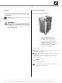
How heat pumps function
Heat pumps work following the principle of a refrigera-
tor: the same technology, only for the opposite use. Re-
frigerators remove heat from food. They then release
this into the room through slats on its rear.
Heat pumps extract heat from the air, earth or ground
water in our surroundings. This heat that is obtained
is prepared in the device and sent on to the hot water.
Even if it is bitterly cold outside, the heat pump will still
extract enough heat as is required for heating a house.
Example sketch of a brine/water heat pump with under-
oor heating:
4
⁄4 = usable energy
ca.
3
⁄4 = environmental energy
ca.
1
⁄4 = external electrical energy
Area of application
Each heat pump can be used in newly installed or existing
heating systems under consideration of the ambient con-
ditions, operating limits and applicable regulations.
Overview "Technical Data/Scope of Supply“.

6
Subject to change without notice | 83050900dUK – Translation into English of the original German operating manual | ait-deutschland GmbH
Heat quantity recording
In addition to the proof of the unit’s efciency,
EEWaermeGalso meets the demand for a heat quantity
recording (hereafter refered to as HQR). The HQR
is mandatory with air/water heat pumps. With brine/
water and water/water heat pumps, a HQR may only be
set up when a forward ow temperature of ≥ 35 °C has
been reached. The HQR must record the total warm
energy release (heating and hot water) in the building. In
heat pumps with heat quantity recording, the analysis is
conducted by the regulator. The regulator displays the
thermal energy that is exchanged from the heating system
in kWh.
Operation
Your decision to opt for a heat pump or heat pump sys-
tem means you can now make a contribution to sparing
the environment over many years thanks to low emis-
sions and lower primary energy use.
You operate and control the heat pump system via the
control panel of the heating and heat pump control.
NOTE.
Ensure that the control settings are correct.
Operating instructions for the heat and heat
pump control.
To ensure that your heat pump or heat pump system op-
erates efciently and ecologically, the following are espe-
cially important:
€
ENERGY SAVING TIP
Avoid unnecessarily high ow temperatures.
A lower ow temperature on the hot water side
increases the efciency of the system.
€
ENERGY SAVING TIP
When letting in fresh air, do not leave windows
open for an extended period in order to save
energy and reduce your heating costs.
Care of the device
You can clean the surface of the device exterior with a
damp cloth and standard cleaning agents.
Do not use cleaning and care agents which scour or
which contain acid and/or chlorine. Media of this type
would irreversibly damage the surfaces and possibly
cause technical damage to the device.
Device maintenance
The cooling circuit of the heat pump requires no regu-
lar maintenance.
According to EU regulation (EC) 517/2014, leak
inspections and maintenance of a log book are required
by law for certain heat pumps!
Log book for heat pumps, Section “Information
on use of the log book”.
The components of the heating circuit and the heat
source (valves, expansion vessels, circulating pumps,
lters, dirt traps) should be inspected as well as cleaned
as needed - at the very least annually - by a qualied
heating or cooling system technician.
The best solution is to conclude a service agreement
with a heating installation company. This will carry out
all the required maintenance work at regular intervals.
CLEANING AND RINSING OF DEVICE COMPONENTS
CAUTION!
Only customer service personnel author-
ised by the manufacturer may clean and
rinse device components. Only liquids rec-
ommended by the manufacturer may be
used for this.
After rinsing the condenser with chem-
ical cleaning agents, a neutralisation of
residues and intensive rinsing with water
will be necessary. When doing so, observe
the technical data of the relevant heat ex-
changer manufacturer.

7
Subject to change without notice | 83050900dUK – Translation into English of the original German operating manual | ait-deutschland GmbH
Faults
In the event of a fault, you can read off the cause of the
fault via the diagnosis program of the heating and circulat-
ing pump control.
Operating instructions for the heat and heat
pump control.
WARNING!
Only customer service personnel author-
ised by the manufacturer may carry out
service and repair work on the compo-
nents of the device.
Scope of supply
Typical scope of supply arrangement:
Compact device with fully-
hermetic compressor, all safety-
relevant components for cold
circuit monitoring, built-in heating
and heat pump control, sensors
mounted in the device for recording
the hot gas and hot water ow
and return temperature
What to do rst:
Check the supplied product for signs of external
damage during delivery…
Check that nothing is missing from the scope of
supply…
Immediately submit a complaint in the event of de-
livery defects.
NOTE.
Note device type.
Overview "Technical Data/Scope of Supply" or
rating plate on the device.

8
Subject to change without notice | 83050900dUK – Translation into English of the original German operating manual | ait-deutschland GmbH
Set-up and Installation
For all work to be carried out:
NOTE.
Observe the locally-applicable accident pre-
vention regulations, statutory provisions, ordi-
nances and directives.
NOTE.
Observe the noise data of the relevant device
type.
Overview "Technical Data/Scope of Supply", sec-
tion "Sound".
INSTALLATION AREA
ATTENTION
Install the heat pump only indoors.
The installation room must be frost-free and
dry.
WARNING!
Please note and follow the respective
relevant local standards, directives and
regulations applicable, especially the
minimum volume necessary depending
on the refrigerant capacity of the relevant
heat pump system (EN 378-1).
Refrigerant Limit
R 134a 0.25 kg/m³
R 404A 0.48 kg/m³
R 407C 0.31 kg/m³
R 410A 0.44 kg/m³
Overview “Technical data / scope of delivery”,
“General unit data” section.
Minimum volume =
Refrigerant capacity [kg]
Limit [kg/m³]
NOTE.
If several heat pumps of the same type are in-
stalled, only one heat pump must be considered.
If several heat pumps of different types are in-
stalled, the heat pump with the largest refriger-
ant capacity must be considered.
TRANSPORT TO THE INSTALLATION SITE
Always comply with the following safety information
during transport:
CAUTION!
Wear protective gloves.
WARNING!
Work with several persons during trans-
port. Remember the weight of the device.
Overview "Technical Data/Scope of Supply", sec-
tion "General Device Data".
WARNING!
The unit can tip when being removed from
the wooden pallet and during transport.
This can result in personal injury and dam-
age to the unit.
– Take suitable precautionary measures
to eliminate the danger of tipping.
AT TE NTIO N
Never use the components and hydraulic con-
nections on the device for transportation pur-
poses.
AT TE NTIO N
Do not tilt the device more than 45° maximum
(applies for every direction).

9
Subject to change without notice | 83050900dUK – Translation into English of the original German operating manual | ait-deutschland GmbH
To avoid damage during transport, you should transport
the unit to the nal installation location in its original
packaging (with packaging on the wooden pallet), using
a lifting truck.
Remove packaging and set extra box aside (will be
needed later on!)...
Transport the unit using a lifting truck...
INSTALLATION
CAUTION!
Several people are required to install the
unit.
NOTICE:
Always comply with the dimensional drawings
for the respektive size.
Overview “Dimensional drawings” and “Clear-
ance dimensions”.
ATTENTION
The heat pump must be placed on a load-bear-
ing, horizontal base. Ensure that the base is de-
signed for the weight of the heat pump.
Do not use a rigid foam boiler platform!
Overview “Technical data/scope of delivery”,
“General unit data” section.
NOTE.
Set up the device so that the control side is ac-
cessible at all times!
ATTENTION
Do not tilt device more than 45° - applies for
every direction!
NOTE.
The openings for the lifting truck must be closed
with the covering plate supplied!.
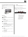
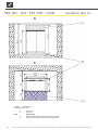
Proceed as follows at the installation site:
Place the device on a load-bearing and horizon-
tal base, preferably insulated from structure-borne
sound…
Detail drawing of concrete foundation:
1 Screed
2 Approx. 100 mm according
to weight of heat pump
3 Insulation from structure-
borne sound according to
weight of heat pump
4 Concrete foundation
5 Edge insulation strip
6 Impact sound insulation
7 Concrete cover

10
Subject to change without notice | 83050900dUK – Translation into English of the original German operating manual | ait-deutschland GmbH
Assembly of the Hydraulic
Connections
AT TE NTIO N
The heat source system must be designed cor-
responding to the specications of the planning
manual.
Heat pump guide and “Hydraulic connection” in-
structions.
NOTICE:
Check to make sure that the diameters and
lengths of the pipes for the heating circuit and
for the heat source are sufciently dimensioned.
NOTICE:
Circulating pumps must be multi-stage. They
must be able to deliver at least the minimum
ow rate required for your model.
Overview “Technical data/scope of delivery”,
“Heat source “ and “Heat circuit” section.
ATTENTION
The hydraulic system must be equipped with a
buffer tank, the required volume of which de-
pends on the model of your unit.
ATTENTION
When installing the connections, always secure
the connections on the unit from twisting, in or-
der to prevent damage to the copper pipes in
the interior of the unit.
Mount shutoff devices on the heating circuit…
Mount shutoff devices on the heat source…
NOTE.
The evaporator and liqueer of the heat pump
can be rinsed, if necessary, when mounting the
shutoff devices.
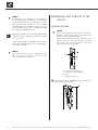
Position a ventilator at the highest point of the heat
source in the heat source outlet…
You need to make the connection to the xed pipe-
work via the compensators (accessories)…
The compensators serve for vibration isolation…
We recommend mounting a dirt lter (screen size
0.9 mm) at the heat source inlet connection (re-
turn)…
The hot water and heat source connections are
marked correspondingly on the device.
For the positioning of the connections, see di-
mensional diagram for the relevant device type.
Screw the compensators onto the connections on
the unit until they bear against the rubber gasket…
Screw the compensators by hand onto the pipes of
the heating circuit and the heat source until they
bear against the rubber gasket…
Tighten all connections one or two turns to achieve
a tight seal…
Do not overtighten. The rubber part of the com-
pensators must not become twisted (torsion). This
could cause malfunctions and even serious damage
to the unit.

11
Subject to change without notice | 83050900dUK – Translation into English of the original German operating manual | ait-deutschland GmbH
Electrical connection work
For all work to be carried out:
DANGER!
Danger of fatal injury due to electric
current!
Electrical connections may be installed
only by qualied electricians.
Before opening the unit, disconnect the
system from the power supply and secure
it from being switched back on!
WARNING!
Observe the appropriate EN, VDE and/or
locally applicable safety regulations during
installation and when carrying out electri-
cal work.
Observe the technical conditions of the
relevant energy supply utility (if the latter
requires this)!
NOTE.
All live wires must be stripped before they are
installed in the cable duct of the switch cabinets!
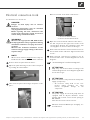
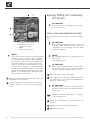
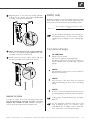
Remove the front panel from the device…
Open the quick fastening screws of the front panel
by rotating 90° anticlockwise…
Take the front panel off its hinges and put in a safe
place…
Gain an overview of the inside of the device…
1 Electrical switch cabinet
2 Device intermediate bottom
Open the electrical switch cabinets of the device…
For this only loosen the upper two screws of the
covering plate. Remove the remaining screws. The
covering plate can then be taken off its hinges…
Route load and external control and sensor lines to
the terminals via the cable duct. Tighten strain relief
screws…
Make electrical connections according to the di-
mensional data of the terminal diagram and circuit
diagrams…
"Terminal Diagram" and "Circuit Diagrams".
ATTENTION .
Only carry out electrical work according to the
terminal diagram and circuit diagrams applicable
for the device type.
ATTENTION
Ensure clockwise rotary eld of the load power
supply (compressor).
– An incorrect rotary eld of the com-
pressor during operation can cause
serious, irreparable damage to the
compressor.
ATTENTION
The power supply for the heat pump must be
equipped with an all-pole miniature circuit-
breaker with at least 3 mm contact spacing to
IEC 60947-2.
Note the level of the release current.
Overview "Technical Data/Scope of Supply", sec-
tion "Electrics".

12
Subject to change without notice | 83050900dUK – Translation into English of the original German operating manual | ait-deutschland GmbH
1 Connection for control
2 Connection for power
compressor 3~PE
3 N/PE
4 Phase sequence relay
NOTE.
The control element of the heat and heat pump
regulator can be a connection with a computer
or network using an network cable designed for
such pruposes, thus allowing the heating and
heat pump regulator to be controlled remotely.
If such a connection is desired, install a screened
network cable (category 6, with RJ-45 plug)
through the unit when installing the connections
and run it through the front facade of the unit,
parallel to the already-present heating and heat
pump regulator control cable.
Close the switch cabinet inside the device after n-
ishing all the electrical work…
Close the front panel of the device if no further in-
stallation work is to be carried out directly after-
wards.
Rinsing, Filling and Ventilating
the System
ATTENTION
The system must be absolutely free from air be-
fore commissioning.
RINSING, FILLING AND BLEEDING THE HEAT SOURCE
Dirt and deposits in the heat source can lead to malfunc-
tions.
ATTENTION .
Before ushing and lling the heat source the
drain pipe of the safety valve must be connected
- Important: do not discharge into the drains
(anti-freeze mixture)!.
NOTE
The following antifreezes are approved for the
brine circuit:
•
Monoethylene glycol
ATTENTION
Ensure that the (pipe) materials, seals and other
components used on site are made of materials
that are compatible with the antifreeze used!
Rinse heat source system thoroughly…
Thoroughly mix the antifreeze available as an acces-
sory with water in the required ratio. Only ll the
heat source after mixing…
ATTENTION
The type amd concentration of the antifreeze in
the water must have the value indicated for your
device type.
Overview “Technical Data/Scope of Supply”,
section “Heat Source”.
Check the concentration of the antifreeze in the
mixture…
Fill the heat source with antifreeze mixture…
Bleed the heat source.

13
Subject to change without notice | 83050900dUK – Translation into English of the original German operating manual | ait-deutschland GmbH
DAMAGE THAT CAN OCCUR IN CASE OF
NON-COMPLIANCE
- Malfunctions and the failure of components (e.g. pumps,
valves)
- Internal and external leaks (e.g. from heat exchangers)
- Cross-section reduction and blockaging of components
(e.g. heat exchanger, pipes, pumps)
- Material fatigue
- Gas bubbles and gas cushion formation (cavitation)
- Negative effect on heat transfer (formation of coatings,
deposits) and associated noises (e.g. boiling noises,
ow noises)
LIMESCALE – THE ENERGY KILLER
Filling with untreated drinking water inevitably leads to
the precipitation of all calcium as scale. The consequence:
limescale deposits form on the heat transfer surfaces of
the heating. The efciency falls and the energy costs rise.
A rule of thumb is that 1 millimetre of limescale deposit
causes an energy loss of 10%. In extreme cases it can
even cause damage to the heat exchangers.
WATER SOFTENING TO VDI 2035 – PART I
If the water is softened before the heating is lled, in
accordance with the VDI 2035 guidelines, no scale
can form. This effectively and permanently prevents
limescale deposits and the resulting negative effects on
the entire heating system.
CORROSION – AN UNDERESTIMATED PROBLEM
VDI 2035, Part II, deals with the problem of corrosion.
Softening the heating water can prove to be insufcient.
The pH value can signicantly exceed the limit of 10.
pH values higher than 11 can set in, which even damage
rubber seals. The VDI 2035, Part 1 guidelines are
fullled, however, VDI 2035, Part 2 suggests a pH value
between 8.2 and maximum 10.
If aluminium materials are used, which is the case in
many modern heating systems, a pH value of 8.5 must
not be exceeded, because otherwise there is a threat
of corrosion – and aluminium is attacked without the
presence of oxygen. Therefore, apart from softening
the heating ll and additional water, the heating water
should also be appropriately conditioned. This is the
only way to comply with the VDI 2035 requirements and
the recommendations and installation instructions of the
heat pump manufacturer.
FLUSHING AND FILLING THE HEATING CIRCUIT
WATER QUALITY
OF THE FILL AND ADDITIONAL WATER IN HOT WATER
HEATING SYSTEMS ACCORDING TO VDI 2035
PART I AND II
Use of modern, energy-efcient heat pump systems
is becoming increasingly widespread. Their ingenious
technology enables these systems to achieve very good
efciencies. The decreasing space available for heat
generators has led to the development of compact
units with increasingly smaller cross-sections and high
capacities. This means the complexity of the systems and
the material diversity are also increasing, which plays an
important role especially in their corrosion behaviour.
The heating water not only affects the efciency of the
system, but also the life of the heat generator and the
heating components of a system.
The guide values of VDI 2035 Part I and Part II must
therefore be complied with as minimum requirements
for proper operation of the systems. Our practical
experience has shown that the safest and most trouble-
free running of the systems is achieved with so-called
low-salt operation.
VDI 2035 Part I gives important information and
recommendations regarding scaling and its prevention in
heating and domestic hot water heating systems.
VDI 2035 Part II primarily deals with the requirements
for reducing heating water corrosion in hot water
heating systems.
PRINCIPLES OF PART I AND PART II
The occurrence of scaling and corrosion damage in hot
water heating systems is low, if
- proper planning and commissioning is carried out
- the system is closed in corrosion terms
- adequately dimensioned pressurising is integrated
- the guide values for the heating water are complied
with
- and regular servicing and maintenance are carried out.
A system log should be kept, in which the relevant
planning data is entered (VDI 2035).

14
Subject to change without notice | 83050900dUK – Translation into English of the original German operating manual | ait-deutschland GmbH
Part 2 of VDI 2035 also points out the reduction in total
salt content (conductivity). The risk of corrosion is far
lower if deionised water is used than is the case if the
system is operated with salty, i.e. softened water.
Even if the water has been softened beforehand, it
contains dissolved, corrosion-promoting salts, which act
as electrolytes due to the use of different materials in
the heating system and therefore accelerate corrosion
processes. This can ultimately result in pitting.
ON THE SAFE SIDE WITH LOW-SALT OPERATION
The problems listed above do not occur at all with
low-salt operation, as neither corrosive salts such as
sulphates, chlorides and nitrates nor alkalising sodium
hydrogen carbonate are in the heating water. The
corrosive properties of deionised water are very low
and in addition, fur cannot form in the boiler. This is the
ideal approach for closed heating circuits, in particular,
because low oxygen input into the heating circuit can
also be tolerated.
In general, when the system is lled with deionised
water, the pH value sets itself within the ideal range due
to „self-alkalinisation“. If necessary, a pH value of 8.2
can be very easily alkalised by adding chemicals. In this
way, optimum protection of the entire heating system is
achieved.
MONITORING
Analytical recording and monitoring of the relevant
water values and the added active conditioning
substances is of decisive importance. Therefore, they
should be monitored regularly using appropriate water
test equipment.
AT TE NTIO N
The drainage pipe must be connected to the
safety assembly before rinsing and lling the heat
circuit.
Thoroughly rinse heat circuit…
NOTE.
Rinse heat pump and heating circuit for about 5
minutes.
Fill heat circuit…
Bleed heat circuit.
Isolation of the Hydraulic
Connections
NOTE.
Insulate the heat source and heat circuit accord-
ing to the standards and directives applicable lo-
cally.
Check leakproofness of all hydraulic connections.
Perform pressure test…
Insulate all connections, vibration isolation, connec-
tions and lines of the heat circuit and heat source.
Provide steam diffusion-tight heat source insula-
tion.

15
Subject to change without notice | 83050900dUK – Translation into English of the original German operating manual | ait-deutschland GmbH
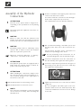
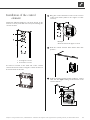
Installation of the control
element
Situated at different heights in the front facade of the
unit are recesses (each with 4 recesses) for fastening the
control element:
1 four upper recesses
2 four lower recesses
4 hooks are located on the back side of the control
element and can be used to hang the control element on
the front facade of the unit:
Hang the control element’s hooks on the recesses
of the front facade (either in the upper or lower
recesses)…
Example:
Control element in upper recesses
Push the control element down until it locks into
position…
Stick the heating and heat pump regulator’s control
cable into the right bushing on the bottom of the
control element…

16
Subject to change without notice | 83050900dUK – Translation into English of the original German operating manual | ait-deutschland GmbH
Installation and removal of the
screen
INSTALLING THE SCREEN
NOTE.
The screen is provided at the time of delivery so
that the control element may be inserted in the
upper recesses of the front facade.
If the control element has been inserted in the
lower recesses of the front facade, you must
rst remove the screen’s temporary cover and
then reinsert it above the logo.
Screen at time of delivery:
1 recess for control element
2 logo
3 temporary cover
First, insert the screen below, in the provided slots
on the front of the facade…
NOTE.
A connection to a computer or a network can
be installed via the left bushing on the bottom
of the control element, thus allowing the heat-
ing and heat pump regulator to be controlled
remotely. One pre-condition is that a screened
network cable (category 6) be installed through
the unit when installing the unit.
Operating manual for the heating and heat pump
regulator, version “Qualied technician”, “Web
server” section.
If this network cable is available, insert the net-
work cable’s RJ-45 plug into the left bushing of
the control element.
NOTE.
The network cable can be exchanged at any
time. In order to be able to connect it, the
screen must rst be removed.

17
Subject to change without notice | 83050900dUK – Translation into English of the original German operating manual | ait-deutschland GmbH
Buffer tank
Hydraulic integration of the heat pump requires a buffer
tank in the heating circuit. The volume required for the
buffer tank can be derived from the following formula:
V
Buffer tank
=
Min. throughput of heating circuit volumetric ow /
hour
10
For the minimum throughput of the heating cir-
cuit volumetric ow, see the overview “Techni-
cal Data/scope of Supply”, section “Heating Cir-
cuit”.
Circulation Pumps
ATTENTION .
Always note the model.
Do not use regulated circulating pumps.
Circulating pumps and domestic hot water cir-
culation pumps must be multi-stage, regulated
pumps.
NOTE:
The minimum hot water, heat source volumetric
ow must be ensured!
NOTE:
The viscosity of the brine must be observed
when dimensioning the heat source circulating
pump!
NOTE:
A motor protection switch for the heat source
circulating pump is integrated in the heat pump!
Setting range “Technical Data/Scope of Supply”
Electrics
For the minimum volumetric ow rate of the
heat circuit/heat source, see overview “Tech-
nical Data/Scope of Supply” section “Heat Cir-
cuit” “Heat Source” for the relevant type.
Beginning rst on one side and moving upwards,
lock the screen’s snap-in lugs in place in the slots
provided on the front of the facade…
Next, on the opposite side, moving upwards.
Lock the screen’s snap-in lugs in place in the slots
provided on the front of the facade…
Finally, press the screen’s upper snap-in lugs into
the slots provided on the front of the facade.
REMOVING THE SCREEN
In order to remove the screen, the snap-in lugs must
rst be loosened by pressing one side completely
toward the middle of the screen. Thereafter,
remove the snap-in lugs from the opposite side.

18
Subject to change without notice | 83050900dUK – Translation into English of the original German operating manual | ait-deutschland GmbH
Domestic Hot Water
Preparation
The domestic hot water preparation with the heat pump
requires a further hot water circuit in addition (paral-
lel) to the heating circuit. During integration, ensure that
the domestic hot water loading is not routed through
the buffer tank of the heating circuit.
Tip “Hydraulic Integration”.
Domestic Hot Water Tank
If the heat pump is to prepare domestic hot water, you
need to incorporate special domestic hot water tanks in
the heat pump system. Select the tank volume so that
the required domestic hot water volume is also available
during a power failure of the public supply utility.
NOTE:
The heat exchanger area of the domestic hot
water tank must be dimensioned in such way
that the heating capacity of the heat pump is
transferred with as little spread as possible.
We shall be pleased to offer domestic hot water tanks
from our product range. They are optimally tailored to
your heat pump.
NOTE:
Integrate the domestic hot water tank in the
heat pump system in such way that it corre-
sponds to the hydraulic scheme suitable for your
system.
Commissioning
NOTE.
The commissioning has to be in the heating
mode.
Carry out a thorough installation check and work
through the general checklist…
Manufacturer’s homepage.
By checking the installation you prevent damage to
the heat pump system, which could be caused by
work carried out improperly.
Check that…
•
clockwise rotary eld of the load power supply
(compressor) is ensured.
•
The heat pump installation and assembly have
been carried out according to the requirements
of this operating manual.
•
the electrical installation work has been
completed properly.
•
The power supply for the heat pump must be
equipped with an all-pole automatic circuit-
breaker with at least 3 mm contact spacing to IEC
60947-2.
•
The heating circuit is ushed, lled and thoroughly
vented.
•
All valves and shut-off devices of the heating
circuit are open.
•
All pipe systems and components of the system
are leaktight.
Carefully ll out and sign the completion report for
heat pump systems...
Manufacturer’s homepage.
Within Germany and Austria:
Send completion report for heat pump systems
and general checklist to the manufacturer’s factory
customer service department…
In other countries:
Send completion report for heat pump systems
and general checklist to the manufacturer’s local
par tne r…
The heat pump system is commissioned by customer
service personnel authorised by the manufacturer.
There is a fee for starting up!

19
Subject to change without notice | 83050900dUK – Translation into English of the original German operating manual | ait-deutschland GmbH
Deinstallation
DANGER!
Danger of fatal injury due to electric cur-
rent!
Electrical connections may be installed
only by qualied electricians.
Before opening the unit, disconnect the
system from the power supply and secure
it from being switched back on!
WARNING!
Only qualied heating and refrigerating
plant technicians may remove the device
from the system.
AT TE NTIO N
The antifreeze mixture of the heat source must
not be disposed of into the sewerage system.
Collect antifreeze mixture and dispose of prop-
erly.
AT TE NTIO N
Provide the device components, coolant and oil
for recycling or properly dispose of them corre-
sponding to the applicable regulations, standards
and directives.
REMOVING THE BACKUP BATTERY
AT TE NTIO N
Before scrapping the heating and heat pump con-
trol, remove the backup battery on the proces-
sor circuit board. The battery can be pushed out
using a screwdriver. Properly dispose of the bat-
tery and electronic components in line with en-
vironmental requirements.

20
Subject to change without notice | 83050900dUK – Translation into English of the original German operating manual | ait-deutschland GmbH
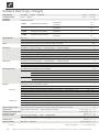
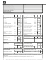
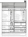
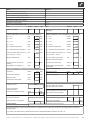
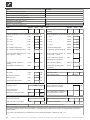
Device designation
Heat pump type Brine/Water ı Air/Water ı Water/Water • relevant ı — not relevant
Installation location Indoors ı Outdoors • relevant ı — not relevant
Conformity CE
Power data Heating power/COP at
B0/W35 Standard point as per EN255
2 Compressors
1 Compressor
kW ı …
kW ı …
B0/W50 Standard point as per EN255
2 Compressors
1 Compressor
kW ı …
kW ı …
B-5/W35 Standard point as per EN255
2 Compressors
1 Compressor
kW ı …
kW ı …
B-0/W45 Standard point as per EN14511
2 Compressors
1 Compressor
kW ı …
kW ı …
Operating limits Heat circuit °C
Heat source °C
Additional operating points …
Noise Sound pressure level at 1m gap around the machine averaged (in free field) dB(A)
Sound power level as per EN12102 dB
Heat source Volumetric flow: minimum throughput ı nominal throughput ı maximum throughput l/h
Pressure loss in heat pump ∆p ı Volumetric flow bar ı l/h
Recommended brine circulating pump …
Total compression of the recommended pump at nominal brine volumetric flow bar ı l/h
Antifreeze Monoethylene glycol
Minimum concentration ı frostproof to % ı °C
Heat circuit Volumetric flow: minimum throughput ı nominal throughput ı maximum throughput l/h
Pressure loss in heat pump ∆p ı Volumetric flow bar ı l/h
Free compression of heat pump ∆p ı Volumetric flow bar ı l/h
Temperature spread for B0/W35 K
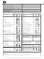
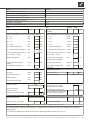
General device data Earth (see dimensional diagram for the size indicated) Size
Total weight kg
Extra weight of construction unit 1 kg
Extra weight of construction unit 2 kg
Connections Heat circuit …
Heat source …
Refrigerant Refrigerant type ı Filling capacity … ı kg
Electrics Voltage code ı All-pole circuit breaker for pump *) … ı A
Voltage code ı Control voltage circuit breaker *) … ı A
Voltage code ı Electrical heating element circuit breaker *) ı A
Heat pump Effective power consumption in the normal point B0/W35 as per EN255: Power consumption ı Current consumption ı cosφ kW ı A ı …
Maximum machine current within the operating limits A
Starting current: direct ı with slow-starter A ı A
Protection type IP
Power of electrical heating element 3 ı 2 ı 1-phase kW ı kW ı kW
Components Circulating pump for heat circuit at nominal throughput: Power consumption ı Current consumption kW ı A
Circulating pump for heat source at nominal throughput: Power consumption ı Current consumption kW ı A
Setting range for motor protection switch of heat source circulating pump A
Passive cooling function Data only for devices with ID K: Cooling power at nominal volumetric ow rates (15 °C heat source, 25 °C hot water) kW
Safety devices Safety assembly for heat circuit ı Safety assembly for heat source in scope of supply: • yes — no
Heating and heat pump control in scope of supply: • yes — no
Electronic soft-starter integrated: • yes — no
Expansion vessels Heat source: Scope of supply ı Volume ı Supply pressure • yes — no ı l ı bar
Heat circuit: Scope of supply ı Volume ı Supply pressure • yes — no ı l ı bar
Overflow valve integrated: • yes — no
Vibration isolation Heat circuit ı Heat source in scope of supply: • yes — no
UK813198a
*) Observe local regulations n.n. = cannot be demonstrated
Technical Data/Scope of Supply
Page is loading ...
Page is loading ...
Page is loading ...
Page is loading ...
Page is loading ...
Page is loading ...
Page is loading ...
Page is loading ...
Page is loading ...
Page is loading ...
Page is loading ...
Page is loading ...
Page is loading ...
Page is loading ...
Page is loading ...
Page is loading ...
Page is loading ...
Page is loading ...
Page is loading ...
Page is loading ...
Page is loading ...
Page is loading ...
Page is loading ...
Page is loading ...
Page is loading ...
Page is loading ...
Page is loading ...
Page is loading ...
Page is loading ...
Page is loading ...
Page is loading ...
Page is loading ...
-
 1
1
-
 2
2
-
 3
3
-
 4
4
-
 5
5
-
 6
6
-
 7
7
-
 8
8
-
 9
9
-
 10
10
-
 11
11
-
 12
12
-
 13
13
-
 14
14
-
 15
15
-
 16
16
-
 17
17
-
 18
18
-
 19
19
-
 20
20
-
 21
21
-
 22
22
-
 23
23
-
 24
24
-
 25
25
-
 26
26
-
 27
27
-
 28
28
-
 29
29
-
 30
30
-
 31
31
-
 32
32
-
 33
33
-
 34
34
-
 35
35
-
 36
36
-
 37
37
-
 38
38
-
 39
39
-
 40
40
-
 41
41
-
 42
42
-
 43
43
-
 44
44
-
 45
45
-
 46
46
-
 47
47
-
 48
48
-
 49
49
-
 50
50
-
 51
51
-
 52
52


Alpha innotec SWP Owner's manual
- Category
- Heat pumps
- Type
- Owner's manual
Ask a question and I''ll find the answer in the document
Finding information in a document is now easier with AI
Related papers
-
Alpha innotec HT Owner's manual
-
-
-
-
-
-
Alpha innotec LW 310A Owner's manual
-
Alpha innotec EP Owner's manual
-
-
Other documents
-
Sega Genesis User manual
-
LG HU091.U43 Owner's manual
-
Steba 33.01.00 Datasheet
-
Alpha-InnoTec WZS 102K3M Operating instructions
-
 SystemAir SYSAQUA45.H.1P-SP.WPS.AVM.T Owner's manual
-
LG HU163.U33 Owner's manual
-
-
LG HM071M.U43 Owner's manual
-
-
