Page is loading ...

**
**
*
PIP-USP2PIP-USP2
PIP-USP2PIP-USP2
PIP-USP2
An IQ System
®
Programmable Input Processor with DSP and
Load Supervision for Crown
®
PIP2-Compatible Amplifiers
Printed on
recycled paper.
125981-4
2/02
© 2002 by Crown Audio, Inc., P.O. Box 1000, Elkhart, IN 46515-1000 U.S.A.
Telephone: 574-294-8000. Fax: 574-294-8329. Trademark Notice: IQ2, SmartAmp,
PIP, and PIP2 are trademarks, and Com-Tech, Crown,
IOC, IQ System, Macro-Tech
and ODEP are registered trademarks of Crown International. Other trademarks are
the property of their respective owners.
Obtaining Other Language Versions:
To obtain information in another language about the use of this product, please
contact your local Crown Distributor. If you need assistance locating your local
distributor, please contact Crown at 574-294-8200.
Note: The information provided in this manual was
deemed accurate as of the publication date. How-
ever, updates to this information may have occurred.
To obtain the latest version of this manual, please
visit the Crown website at www.crownaudio.com.

IQ-PIP-USP2
Page 3
IQ-PIP-USP2 Reference Manual
IQ-PIP-USP2
Page 2
IQ-PIP-USP2 Reference Manual
Quick Install Procedure
This procedure is provided for those who are already familiar with Crown’s
IQ
System
®
and who would like to install the
IQ-PIP-USP2
in the shortest time possible.
Less experienced installers or those wishing a full explanation of the installation
procedure are encouraged to go to Section 3 where the full installation procedure
is described.
Prepare the IQ-PIP-USP2:
1. Set the IQ address switch S1 (see Figures 2.1 and 3.1) on the IQ-PIP-USP2 to
an unused IQ address. (Tip: Record the IQ address on the small field labeled
“IQ ADDRESS” that is provided on the PIP panel.)
2. Set the Input/Output Scaling switch S3 (see Figures 2.1 and 3.2) for the desired
scaling.
Prepare the amplifier:
3. Turn down the level controls of the amplifier and turn off the amplifier.
4. Unplug the power cord of the amplifier from the AC mains.
5. Remove the existing
PIP
™ or cover panel from the amplifier back panel (two
screws).
Install the IQ-PIP-USP2 into the amplifier:
6. Carefully ground yourself to the chassis of the amplifier before installing the IQ-
PIP-USP2. It is a good idea to maintain ground contact between yourself and
the amplifier while inserting the module into the amplifier in the next step.
7. Turn the PIP upside down so you can clearly see the two ribbon cable connec-
tors located on the underside of the board near the back corner (see Figure
2.1). Attach the ribbon cables from your amp to the ribbon-cable connectors.
The 20-pin cable should be connected first, then the 18-pin cable should be
connected. Both ribbon cables should run untwisted from the amplifier to the
PIP module.
Important: Be careful when attaching the ribbon cable to the connector that
the cable is properly seated before applying pressure to the connector. Forc-
ing the cable onto the connector could cause the keying tabs, which ensure
proper pin alignment, to break. Connecting the ribbon cables with improper
pin alignments may result in damage to the PIP
When both cables are firmly attached, turn the IQ-PIP-USP2 back to an upright
position and insert into the PIP opening in the back of the amplifier. Take care
while inserting the PIP to make sure you do not crimp, pinch or stretch the
ribbon cables.
8. Tighten the two PIP mounting screws until it is secured to the amplifier back
panel, making sure the supplied star-washers penetrate the powder-coat fin-
ish of the PIP panel for good ground connection.
Install the wiring:
9. Connect the IQ-PIP-USP2 to the IQ System via the Crown Bus (see Section
3.4 if more information is needed).
10. Connect the audio signal wiring to the IQ-PIP-USP2 (see Section 3.4 if more
information is needed).
11. Connect the amplifier back to the AC mains.
The information furnished in this manual does not include all of the details
of design, production, or variations of the equipment. Nor does it cover
every possible situation which may arise during installation, operation or
maintenance. If you need special assistance beyond the scope of this
manual, please contact Crown Technical Support.
Crown Technical Support
1718 W. Mishawaka Rd., Elkhart, Indiana 46517 U.S.A.
Phone: 800-342-6939 (North America, Puerto Rico and Virgin
Islands) or 219-294-8200
Fax: 574-294-8301 Internet: http://www.crownaudio.com
WARNING
TO REDUCE THE RISK OF ELECTRIC
SHOCK, DO NOT EXPOSE THIS
EQUIPMENT TO RAIN OR MOISTURE!
FCC COMPLIANCE NOTICE
This equipment has been tested and found to comply with the
limits for a Class A digital Device, pursuant to Part 15 of the FCC
Rules. These limits are designed to provide reasonable
protection against harmful interference when the equipment is
operated in a commercial environment. This equipment
generates, uses and can radiate radio frequency energy and, if
not installed and used in accordance with the instruction manual,
may cause harmful interference to radio communications.
Operation of this equipment in a residential area is likely to cause
harmful interference in which case the user will be required to
correct the interference at his own expense.
“The user is cautioned that any changes or modifications not
expressly approved by Crown International could void the user’s
authority to operate the equipment.”

IQ-PIP-USP2
Page 5
IQ-PIP-USP2 Reference Manual
IQ-PIP-USP2
Page 4
IQ-PIP-USP2 Reference Manual
ILLUSTRATIONS
CONTENTS
1 Welcome ................................................... 6
1.1 Unpacking ........................................ 7
2 Controls, Connectors & Indicators ......... 8
3 Installation ................................................. 9
3.1 Prepare the IQ-PIP-USP2 ............... 9
3.2 Prepare the Amplifier .................... 10
3.3 Install the IQ-PIP-USP2 into the
Amplifier.............................................. 10
3.4 Install the Wiring .........................11
3.5 Adjust System Levels ................. 14
4 Operation ................................................ 15
4.1 Hardware & Firmware ................ 15
4.1.1 Data Signal Presence
Indicator ...................................... 15
4.1.2 Preset Indicator ............... 15
4.1.3 Crown Bus Input/
Output Connector ....................... 15
4.1.4 Crown Bus Daisy
Output Connector ....................... 16
4.1.5 Balanced Audio
Outputs ........................................ 16
4.1.6 Balanced Daisy
Outputs ........................................ 16
4.1.7 AUX Input/Output
and Listen Bus Connector ......... 16
4.1.8 Crown Bus “Drop
Out” Relays ................................. 16
4.2 Hardware Controls ...................... 16
4.2.1 Daisy Select
Jumpers....................................... 16
4.2.2 IQ Address Switch
(S1) ............................................. 17
4.2.3 Scaling Switch (S3)....... 1 7
4.2.4 Reset/Preset Switch ...... 1 7
4.3 Amplifier Control and
Monitoring ................................... 18
4.3.1 User Presets ................... 1 8
4.3.2 IOC Event Monitor .............. 18
4.3.3 Input Signal Level
Monitor ........................................ 18
4.3.4 Output Signal
Level Monitor .............................. 18
4.3.5 Thermal Headroom
Level Monitor .............................. 18
4.3.6 Power Control .................. 19
4.3.7 Signal Mute ...................... 19
4.3.8 Polarity Inverter............... 19
4.3.9 Input Signal
Attenuator.................................... 19
4.3.10 “Ghost Faders” .............. 19
4.3.11 Memory Backup ............ 19
4.3.12 Amp Information ........... 19
4.3.13 Amp Mode .....................19
4.3.14 Amp Output
Mode ............................................ 19
4.3.15 Error Reporting ............. 20
4.4 Signal Processing ....................... 20
4.4.1 Signal Processing
Forms ........................................... 20
4.4.2 Signal Routing ................. 21
4.4.3 Auto Standby ................... 21
4.4.4 Input Signal ...................... 21
4.4.5 Programmable
Filters ........................................... 22
4.4.6 Signal Delay .................... 24
4.4.7 Peak Voltage
Limiter.......................................... 25
4.4.8 Average Power
Limiter.......................................... 25
4.4.9 Clip Eliminator ................. 25
4.4.10 Thermal Limiter ............. 25
4.4.11 Output Trim
Controls ...................................... 26
4.4.12 Tie Switch ..................... 26
4.5 Load Supervision ........................... 26
5 IQ Audio In Depth ................................... 28
5.1 A Closer Look at Audio
Signal Wiring .............................. 28
5.2 A Closer Look at Crown
Bus Wiring .................................... 29
5.2.1 “Hub” Style Crown
Bus Wiring................................... 30
5.3 Using the AUX
Connector .................................... 31
5.3.1 AUX Output ......................... 31
5.3.2 AUX Input ........................... 32
5.4 Listen Bus ...................................... 33
5.5 Working with RJ-11 and
RJ-45 Connectors ...................... 33
5.6 Q-Factor Calculation ................... 34
5.7 Load Supervision
Applications ................................ 35
5.7.1 Typical Load
Characteristics to Know
and Understand .......................... 36
6 Specifications ......................................... 37
7 IQ Address Tables .................................. 39
8 Using the IQ-PIP-USP2 with the
IQ-PIP-USP2 Adapter ........................ 43
9 Service ................................................. 48
Warranty ................................................. 50
Factory Service Information Form ........... 53
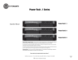
1.1 IQ-PIP-USP2 Front Panel ...................... 6
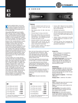
2.1 IQ-PIP-USP2 Controls,
Connectors and Indicators ................. 8
3.1 Address Switch (S1) .......................... 9
3.2 Scaling Switch (S3) ......................... 10
3.3 Scaling Chart ..................................... 10
3.4 Installing the IQ-PIP-USP2 ................... 11
3.5 Crown Bus Wiring “Loops” from Output to
Input 12
3.6 RJ-45 Mating Plug ................................ 12
3.7 RJ-45 Output to Barrier
Block Input ........................................ 12
3.8 RJ-45 Output to Din Input. .............. 1 3
3.9 RJ-45 Input to Barrier
Block Output. .................................... 1 3
3.10 RJ-45 Input to Din Output. ........... 13
3.11 RJ-45 Output to RJ-45 Input. ....... 1 4
4.1 Daisy Select Jumper Settings ........ 1 6
4.2 IQ-PIP-USP2 Signal Flow
Block Diagram ...................................... 27
5.1 Audio Input Wiring ................................ 28
5.2 Audio Output Wiring .............................. 28
5.3 Example “Hub” Style Crown Bus Wiring
Arrangement ........................................ 31
5.4 The Internal AUX Circuit ....................... 32
5.5 A Sample AUX Output Circuit ............... 32
5.6 Listen Bus Connection ......................... 33
5.7 Multi-Amp Listen Bus
Configuration ...................................... 33
5.8 RJ-11& RJ-45 Pin Assignment ....... 33
5.9 Q-factor vs. Bandwidth ..................... 34
7.1 IQ Address Switch (S1)
Settings, 0 to 83 ................................40
7.2 IQ Address Switch (S1)
Settings, 84 to 167 ............................ 41
7.3 IQ Address Switch (S1)
Settings, 168 to 250 ............................. 42
8.1 “General” Tab Showing Identification of
IQ-PIP-USP2 Adapter .......................... 45
8.2 “Signal Path” Tab Showing Peak Voltage
and Average Power Limiters Disabled . 45
8.3 “Peak Voltage Limiter” Block Disabled on
“Signal Path” Tab .................................. 46
8.4 “Average Power Limiter” Block Disabled
on “Signal Path” Tab ............................. 46
8.5 “Error Reporting” Tab Showing Fault and
Load Error Reporting Disabled ............ 47
8.6 “Load Supervision” Tab Showing Load
Supervision Disabled ........................... 47

IQ-PIP-USP2
Page 7
IQ-PIP-USP2 Reference Manual
IQ-PIP-USP2
Page 6
IQ-PIP-USP2 Reference Manual
1.1 Unpacking
The unit is shipped in a protective
antistatic bag.
CAUTION: STATIC ELECTRICITY
MAY DAMAGE THE UNIT. Use cau-
tion when handling the unit. Care-
fully ground yourself
BEFORE touch-
ing the unit. Avoid unnecessarily
touching the components or solder
pads on the circuit boards.
Please unpack and inspect the unit
for any damage that may have oc-
curred during transit. If damage is
found, notify the transportation com-
pany immediately. Only you, the
consignee, may initiate a claim with
the carrier for shipping damage.
Crown will be happy to cooperate
fully as needed. Save the shipping
carton as evidence of damage for
the shipper’s inspection.
Even if the unit arrived in perfect
condition, as most do, save all pack-
ing materials. NEVER SHIP THE
UNIT WITHOUT THE FACTORY
PACK.
1 Welcome
The IQ-PIP-USP2 is a PIP (Pro-
grammable Input Processor) input
module for Crown
PIP2
-compatible
amplifiers.* It connects the amplifier
to the Crown Bus of an IQ System,
allowing the amplifier to be controlled
and monitored via IQ.
The IQ-PIP-USP2 is an
IQ2
™
-series
component. This means it supports
Crown’s UCODE protocol and re-
quires an
IQ System
®
with an IQ2-
compatible IQ interface. UCODE
(universal code) enables users and
third parties to develop custom soft-
ware objects to control and monitor
IQ2-compatible components like the
IQ-PIP-USP2.
The IQ-PIP-USP2 is Crown’s sec-
ond generation DSP (digital signal
processing) based IQ
PIP module,
utilizing the latest advancements in
DSP technology to provide state-of-
the-art features and performance. It
offers a variety of programmable
functions such as crossover and sig-
Figure 1.1 IQ-PIP-USP2 Front Panel
nal delay, input compressors, multi-
mode (peak, average, clip) output
limiters, DSP filters, load supervi-
sion, AUX input and output, and
Listen Bus, as well as a host of other
useful features similar to those in-
cluded with our other
SmartAmp
™
IQ PIPs.
A full 24-bit signal path is achieved
by utilizing state-of-the-art 24-bit
Delta-Sigma Analog-to-Digital and
Digital-to-Analog converters. Digi-
tal signal processing is handled by
a 24-bit Motorola DSP running at 66
MHz.
Each IQ-PIP-USP2 includes an IQ
address switch allowing the unit to
have a unique address on the Crown
Bus. It is powered by the amplifier
and includes a memory backup fea-
ture that enables the amplifier to
resume operation with all of its set-
tings intact after a power outage.
This manual will help you success-
fully install your unit. We strongly
recommend you read all the instruc-
tions, warnings and cautions con-
tained within. Also, for your protec-
tion, please send in the warranty
registration card today and save
the bill of sale since it is your official
proof of purchase.
* You must have a PIP2-compatible
amplifier or an IQ-PIP-USP2 Adapter to
use the IQ-PIP-USP2. To determine if
your amplifier is PIP2-compatible, look
for the logo on the back of
the amplifier. The IQ-PIP-USP2 may
not be compatible with some older
Crown PIP amplifiers.

IQ-PIP-USP2
Page 9
IQ-PIP-USP2 Reference Manual
IQ-PIP-USP2
Page 8
IQ-PIP-USP2 Reference Manual
3 Installation
Before beginning, please carefully
note:
CAUTION: STATIC ELECTRICITY
MAY DAMAGE THE IQ-PIP-USP2
MODULE. Use caution when han-
dling the unit. Carefully ground your-
self BEFORE touching the IQ-PIP-
USP2 module. Avoid unnecessarily
touching the components or solder
pads on the circuit boards.
3.1 Prepare the IQ-PIP-
USP2
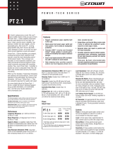
1. Set the IQ address switch S1. By
giving each IQ component a
unique address, it can be
individually controlled and
monitored. Whenever the IQ
System wants to send a command
to just one IQ component, it first
sends its address and then the
command down the Crown Bus.
S1 has eight segments because it
actually contains eight tiny
switches inside. The word “ON” is
printed on the switch along its
upper left side to indicate the ON
position and the switches are
numbered along the bottom
(Figure 3.1).
Each of the eight switches in S1
has a value which doubles as the
switch number increases. For
example switch 1 has a value of 1;
switch 2 has a value of 2; switch 3
has a value of 4; switch 4 has a
value of 8 and so on.
The address is determined by
adding the values of all “ON”
switches. In Figure 3.1, switches 1,
3, 4 and 7 are on. Simply add the
values to find the address:
1+4+8+64=77.
A convenient series of IQ address
tables are included in Section 6.
The tables show the switch
settings for all 250 addresses.
No two IQ components of the
same type which are connected to
the
same Crown Bus can have the
same address.* Suppose, for
example, an IQ System has two
Crown Bus loops, 1 and 2, and this
IQ-PIP-USP2 is to be installed into
loop 1 and given an address of 77.
No other IQ
PIPs can be given the
same address in loop 1. However,
an IQ
PIP in loop 2 can have the
same address.
Different IQ components in the
same Crown Bus loop can have
the same address. For example,
both an IQ–USM 810 mixer/
processor and an IQ-PIP-USP2
can use address 77 in the same
loop.
Figure 3.1 Address Switch (S1)
Figure 2.1 IQ-PIP-USP2 Controls, Connectors and Indicators
2 Controls, Connectors & Indicators
* Note: All IQ PIP modules (IQ-PIP-DSP,
IQ-PIP-MEM, IQ-PIP-SMT, etc.) are
considered the same type, and so may
not share the same address on the
same Crown Bus.

IQ-PIP-USP2
Page 11
IQ-PIP-USP2 Reference Manual
IQ-PIP-USP2
Page 10
IQ-PIP-USP2 Reference Manual
5. Remove the existing
PIP
from
the amplifier back panel (two
screws). This may involve
disconnecting the PIP from a PIP2
input adapter. If a PIP2 input
adapter is already present,
remove the ribbon cables from the
adapter.
3.3 Install the IQ-PIP-USP2
into the Amplifier
6. Carefully ground yourself to the
chassis of the amplifier before
installing the IQ-PIP-USP2. It is a
good idea to maintain ground
contact between yourself and the
amplifier while inserting the
module into the amplifier.
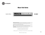
7. Install the IQ-PIP-USP2
into the
amplifier:
Turn the IQ-PIP-USP2 over so that
you can clearly see the two ribbon-
cable connectors located on the
underside of the circuit board (see
Figure 3.4). Connect the two input
ribbon cables of the amplifier. The
20-pin cable (A) should be
connected first, then the 18-pin
cable (B) should be connected.
Both ribbon cables should run
smoothly from the amplifier to the
PIP card (see Figure 3.4).
Important: Be careful when
attaching the ribbon cable to the
connector that the cable is
Figure 3.4 Installing the
IQ-PIP-USP2
3.2 Prepare the Amplifier
3. Turn down the level controls (full
counterclockwise) and turn off the
amplifier.
4. Disconnect the amplifier’s
power cord.
A valid IQ address is any number
from 1 to 250. Do not use a number
higher than 250 since they are
reserved for special use. An
address of “0” (zero) should only
be used for “stand alone” mode.
Setting the address switch to “0”
disables the IQ bus port.
2. Set the scaling switch S3. Input
and output scaling is adjusted via
this four-segment switch. The
word “ON” is printed on the switch
along its upper left side to indicate
the ON position and the switches
are numbered along the bottom
(Figure 3.2). Refer to the chart in
Figure 3.3 for possible scaling
combinations. The factory-default
setting is +20 dBu. Figure 3.2
shows S3 set for +20 dBu.
S3
Figure 3.2 Scaling Switch (S3)
gnilacStuptuO/tupnI
hctiwS noitcnuF
uBd02+ uBd01+
1tupnI1HCNOFFO
2tupnI2HCNOFFO
3tuptuO1HCFFONO
4tuptuO2HCFFONO
Figure 3.3 Scaling Chart
properly seated before applying
pressure to the connector.
Forcing the cable onto the
connector could cause the keying
tabs, which ensure proper pin
alignment, to break. Connecting
the ribbon cables with improper
pin alignments may result in
damage to the
PIP.
When both cables are firmly
attached, turn the IQ-PIP-USP2
back to an upright position and
insert into the
PIP opening in the
back of the amplifier. Take care
while inserting the
PIP to make
sure you do not crimp, pinch or
stretch the ribbon cables.
8. Tighten the two PIP mounting
screws until the
PIP is secured to
the amplifier back panel. Be sure
to use the supplied star-
washers for good ground
connection.
9. Reconnect the amplifier to the
AC receptacle.
3.4 Install the Wiring
10. Connect the IQ-PIP-USP2
t
o
the IQ system via the Crown
Bus. The IQ components in a
Crown Bus loop are wired
sequentially. The loop begins and
ends with the IQ interface. The
output of one IQ component
“loops” to the input of the next and
so on as shown in Figure 3.5.
There are three different types of
connectors used for Crown Bus
wiring on IQ components. These
include DIN connectors, screw
terminal plugs, and RJ-45
connectors. The IQ-PIP-USP2
As an option, switches 1, 2, 3 and 4
may be all set to the ON position,
which provides +20 dBu
headroom on the input, reduces
gain in the output gain stage by 10
dB, and improves system noise
floor.

IQ-PIP-USP2
Page 13
IQ-PIP-USP2 Reference Manual
IQ-PIP-USP2
Page 12
IQ-PIP-USP2 Reference Manual
Figure 3.8 RJ-45 Output to Din Input.
Figure 3.7 RJ-45 Output to Barrier Block Input.
Figure 3.6 RJ-45 Mating Plug
The following examples show how to connect the IQ-PIP-USP2 to other IQ
components:
Figure 3.5 Standard Crown Bus
Wiring “Loops” from the Output to
the Input of each IQ Component (for
Hub-Style Crown Bus wiring, see
Section 5.2.1).
uses RJ-45 connectors that accept
standard RJ-45 plugs like the one
shown in Figure 3.6, allowing the
use of industry-standard straight-
thru type network cables. The top
RJ-45 connector is used for input/
output and the bottom RJ-45
connector is used for daisy output.
Figure 3.9 RJ-45 Input to Barrier Block Output.
Figure 3.10 RJ-45 Input to Din Output.

IQ-PIP-USP2
Page 15
IQ-PIP-USP2 Reference Manual
IQ-PIP-USP2
Page 14
IQ-PIP-USP2 Reference Manual
4 Operation
With an IQ-PIP-USP2 module,
your Crown amplifier can be moni-
tored and controlled from a remote
location through the use of an IQ
System. This PIP module features
SmartAmp
™
capabilities which will
enable the amplifier to function au-
tomatically. For example, the IQ-PIP-
USP2 can automatically turn off the
high voltage supplies of the amplifier
when no input signal is present. This
can lower electrical usage and pro-
vide long-term cost savings. The IQ-
PIP-USP2 can also automatically
limit the audio signal and detect and
report various problems.
The IQ-PIP-USP2 also features digi-
tal signal processing capabilities
including signal delays and a wide
variety of filters.
In addition, the IQ-PIP-USP2
Load Supervision feature has the
ability to verify the status of the loads
in real time.
The IQ-PIP-USP2 uses Crown’s IQ2
protocol. This makes it possible for a
user to design custom graphic dis-
play modules to control and monitor
the unit with IQ2-compatible IQ soft-
ware. This allows even greater flex-
ibility within Crown’s IQ software via
custom control pages. Plus, the IQ2
protocol provides for third-party pro-
gramming for system controllers
such as those from AMX and
Crestron.
The following sections describe the
IQ-PIP-USP2 features and opera-
tion. Where specified, some features
are accessed via controls located
on the unit itself. However, many of
the features can be controlled or
configured using IQ for Windows soft-
ware. Commands are transmitted
via an IQ interface to the specified IQ
component (an IQ2-compatible in-
terface is required). Please contact
your Crown representative or
Crown’s Technical Support Group if
you are unfamiliar with IQ software.
4.1 Hardware
4.1.1 Data Signal Presence
Indicator
An amber Data Signal Presence In-
dicator (DATA) is provided on the
front panel. It flashes whenever com-
mands addressed to the IQ-PIP-
USP2 are received. To assist with
troubleshooting, an option that
forces the DATA indicator to remain
lit is available through IQ software.
4.1.2 Preset Indicator
A green PRESET indicator is pro-
vided on the front panel. This indica-
tor signals the number of the cur-
rently selected preset by emitting a
series of flashes which match the
preset number, followed by a pause.
The indicator will continuously re-
peat the number selected until a
change is made to any setting.
4.1.3 Crown Bus Input/Output
Connector
An RJ-45 connector provides both
input and output connection to the
Crown Bus. This connector is used
for input in a conventional Crown
Bus wiring configuration, and can
be used for both input and output
when a “hub” style Crown Bus wir-
ing configuration is implemented
(see Section 5.2). Drop-out relays
maintain loop integrity in the event
power is removed from the IQ-PIP-
11. Connect the audio signal
wiring to the IQ-PIP-USP2. Two
female XLR connectors, one for
each channel, are provided for
signal input. Two male XLR
connectors, one for each channel,
are provided for audio daisy
chaining. See Section 5.1 for more
information on audio wiring.
Figure 3.11 RJ-45 Output to RJ-45 Input.
12. Reconnect amplifier to the AC
receptacle.
3.5 Adjust System Levels
13. Adjust attenuator levels both on
the amplifier and on the IQ-PIP-
USP2 control panels within your IQ
software for optimum system gain.

IQ-PIP-USP2
Page 17
IQ-PIP-USP2 Reference Manual
IQ-PIP-USP2
Page 16
IQ-PIP-USP2 Reference Manual
An 8-section DIP switch is used to
set the IQ address of the unit. A valid
IQ address is any number from 1 to
250. Numbers higher than 250 are
reserved for special use. An ad-
dress of “0” places the unit in stand-
alone mode. In this mode, the IQ
bus port is disabled and the PIP will
not function with IQ software.
This switch is located on the under-
side of the circuit board. Each IQ
component on a Crown Bus is given
a unique IQ address so it can be
independently controlled and moni-
tored. Two or more IQ components
of the same type should NEVER have
the same address on the same
Crown Bus loop.
For information on setting the IQ
Address Switch, see Section 3.1.
4.2.3 Scaling Switch (S3)
A 4-section DIP switch is used to set
the input and output scaling. This
switch is located on the under-side
of the circuit board. The factory-
default setting is +20dBu.
For information on setting input
and output scaling, see Section 3.1.
4.2.4 Reset/Preset Switch
A recessed reset/preset switch, ac-
cessible from outside the PIP panel,
performs two functions. First, it en-
ables the IQ-PIP-USP2 to be re-
stored to factory default settings,
and second, allows the user to re-
call any of ten presets. A straight-
ened paper clip or similar small ob-
ject is required to press the reset
switch.
To select one of the ten presets,
complete the following steps:
Remove all input signals. With the
power on, briefly press the switch for
less than two seconds to toggle
through the 10 user-defined presets
stored in firmware. Each press will
increment the selected preset by
one. After the switch is released, the
DATA light will flash rapidly for a
moment, then the PRESET indicator
will blink to indicate the preset num-
ber selected. Restore input signals.
To restore the unit to the factory
default settings, complete the fol-
lowing steps:
Remove all input signals. With the
power on, press the switch and hold
for more than 2 seconds, or until the
DATA indicator blinks twice, and all
settings will be reset to factory de-
fault. When the switch is released,
the DATA indicator will flash rapidly
for a moment. Restore input signals.
To clear all memory and set to
factory default presets:
Important: This action will re-write
the flash memory and erase stored
presets. The settings will be reset
to factory default, with the firmware
re-writing to flash memory.
Remove all input signals. Apply
power. Press and hold the switch.
The Data and Preset lights will si-
multaneously flash. After 7 flashes,
release the switch when the lights
are on. Lights will flash back and
forth, then data light will flash by
itself. If this does not occur, repeat
the process.
After the unit has been reset to the
factory default settings, it will behave
like a standard
PIP until it is repro-
grammed by an IQ System. Restore
input signals.
USP2.
4.1.4 Crown Bus Daisy Output
Connector
An RJ-45 connector is provided for
normal daisy wiring output to the
next device on the loop in the Crown
Bus.
4.1.5 Balanced Audio Inputs
A female XLR connector is provided
for balanced audio input to each
channel of the amplifier. Do not use
the Ch.2 input if the amplifier is
configured in either Bridge or Par-
allel-Mono mode.
4.1.6 Balanced Daisy Outputs
A male XLR connector is provided
for balanced audio daisy chaining
for each channel. Each daisy output
connector can be set to pass pro-
cessed or unprocessed signal from
its respective channel via jumper
settings.
4.1.7 AUX Input/Output and
Listen Bus Connector
An RJ-11 connector provides three
functions. The AUX output delivers
15 VDC at 10 mA maximum output
when switched on and may be con-
trolled via software or may be pro-
grammed to switch when a fail con-
dition is present on any channel.*
The high-impedance (10 K ohm) AUX
input can sense logic signals and
can be programmed to activate sys-
tem mute or report fault conditions
when a logic high is present. (See
Section 5.3.2 for more information.)
Either amplifier channel’s output can
be monitored as a balanced line
level signal which is sent to pins 1
and 6 of the RJ-11 connector (soft-
ware selectable).
4.1.8 Crown Bus “Drop Out”
Relays
“Drop out” relays are provided on
the Crown Bus ports to maintain the
continuity of the IQ communication
loop even if the IQ-PIP-USP2
loses power.
4.2 Hardware Controls
The following IQ-PIP-USP2 controls
are accessed via hardware switches
located on the unit:
4.2.1 Daisy Select Jumpers
Jumpers select through or pro-
cessed signal daisy routing to the
Channel 1 and Channel 2 daisy XLR
connectors. The Channel 1 daisy
connector can be set for through
(IN) or processed (OUT) signal from
Channel 1, and the Channel 2 daisy
connector can be set for through
(IN) or processed (OUT) signal from
Channel 2. See Figure 4.1.
4.2.2 IQ Address Switch (S1)
* The AUX output uses inverse logic
when it is configured to report a fail
condition. Normally high, it switches
low when any channel fails a test. In this
way it can also indicate a power loss.
DSY1
DSY2
OUT IN
Figure 4.1 Daisy Select Jumper
settings for through routing for both
Channel 1 and Channel 2 signals.

IQ-PIP-USP2
Page 19
IQ-PIP-USP2 Reference Manual
IQ-PIP-USP2
Page 18
IQ-PIP-USP2 Reference Manual
Each channel’s high-voltage supply
can be independently turned on and
off.
4.3.7 Signal Mute
The output signal of each channel
can be independently muted. This
function typically provides 80 dB or
more of attenuation.
IMPORTANT: The daisy chain out-
puts are also muted by activation of
this function if selected for “pro-
cessed” out.
4.3.8 Polarity Inverter
The polarity of the input signal of
each channel can be independently
inverted.
4.3.9 Input Signal Attenuator
An attenuator at the input of each
channel is used to control the input
signal level. Each attenuator has a
range from 0 dB to –80 dB in ½ dB
steps. (Zero equals no attenuation.)
4.3.10 “Ghost Faders”
These indicators let you monitor the
signal path gain where it may differ
from manual gain set on input at-
tenuation and output trim as the re-
sult of limiting or compression. They
appear as flying faders “behind” the
input attenuators.
4.3.11 Memory Backup
A memory backup feature is pro-
vided which can be disabled, if de-
sired. The factory default setting is
“enabled.” When enabled, the
memory backup stores all run-time
parameters that can be controlled
by the IQ software into nonvolatile
flash memory. Memory backup oc-
curs within 2 seconds after any pa-
rameter change. When disabled, all
run-time parameters are returned to
the last backed-up values whenever
the unit loses power.
CAUTION: Care should be taken to
backup “safe” levels for the input
attenuators and output trim controls.
Changes made after disabling
backup are not saved; therefore, it is
possible for the memory backup fea-
ture to be turned off with “unsafe”
levels stored. This may result in sig-
nificantly greater system gain the
next time power is re-applied to the
IQ-PIP-USP2.
4.3.12 Amp Information
Several useful items of information
about the host amplifier are deter-
mined by the IQ-PIP-USP2 at start-
up. These include manufacturer,
model, date code, serial number,
and revision level. These can be
printed from the system inventory.
4.3.13 Amp Mode
The Stereo (Dual), Bridge-Mono or
Parallel-Mono mode of the amplifier
can be stored in the IQ-PIP-USP2’s
memory so the IQ System is aware
of the position of the amplifier’s out-
put mode switch. Storing this setting
serves as an “electronic reminder” to
the system; however, the actual
mode of the amplifier cannot be con-
trolled with this setting. The software
amp mode setting can be displayed
or modified via IQ for Windows soft-
ware.
4.3.14 Amp Output Mode
On Com-Tech series amplifiers, the
output mode of the amplifier can be
stored in the IQ-PIP-USP2’s memory
so the IQ System is aware of the
amplifier’s output mode setting. This
software switch also scales the out-
4.3 Amplifier Control and
Monitoring
The following IQ-PIP-USP2 features
are accessed via IQ for Windows
software.
4.3.1 User Presets
The parameters for all functions can
be saved as presets. A total of ten
user presets can be stored in the IQ-
PIP-USP2’s flash memory. Preset
names are stored on the PIP
4.3.2 IOC Event Monitor
The Input/Output Comparator (
IOC
®
)
of each channel of the amplifier can
be monitored by the IQ System. The
IOC circuitry acts as a sensitive dis-
tortion meter to provide you
proof of
distortion-free performance
. If dis-
tortion of any kind equals or exceeds
0.05%, the IOC circuit will cause an
IOC Event Monitor on the front of the
amplifier to flash. The IQ-PIP-USP2
can cause a warning to flash on your
computer screen via IQ for Windows
software indicating an IOC event,
Also, it can report IOC events to it’s
AUX port.
4.3.3 Input Signal Level Monitor
The input signal level of each chan-
nel can be monitored. This monitor
feature has a range from +20 dBu to
–40 dBu in ½-dB steps.
4.3.4 Output Signal Level
Monitor
The output signal level of each chan-
nel of the amplifier can be moni-
tored. This monitor feature has a
range from 0 dB to –40 dB where 0
dB is referenced to the rated output
voltage of the amplifier model.*
The IQ-PIP-USP2 features scaled
output level meters. By factory de-
fault, the meters are calibrated such
that 0 dB equals the amplifier’s rated
output into 4 or 8 ohms. If the IQ-PIP-
USP2 is installed into a Com-Tech
®
amplifier, the meters default to 0 dB
equals 70 Vrms. Changing the 4/8 -
70V mode software switch selects
the respective scaling.
4.3.5 Thermal Headroom Level
Monitor
The Thermal Headroom level** of
each channel of the amplifier can be
monitored by the IQ software. This
level represents the percent of avail-
able power/thermal capacity that is
currently being used within the out-
put section of the amplifier. When
the thermal headroom level reaches
100%, the amplifier cannot produce
any more power and it will begin to
limit the drive level to the output
devices to protect them from too
much stress.*** The Thermal Limiter
feature of the IQ-PIP-USP2 can be
set to engage upon a pre-selected
thermal level. (See Section 4.3.15)
4.3.6 Power/Standby Control
* This is assumed to be 70V or the rated
8-ohm output for Com-Tech amplifiers
or the rated 8-ohm output voltage for all
other amplifiers.
** Thermal Headroom on your Crown am-
plifier may be labeled Output Device
Emulation Protection (ODEP)
*** See the amplifier’s
Reference
or
Owner’s Manual
for more information
about ODEP and how it works.

IQ-PIP-USP2
Page 21
IQ-PIP-USP2 Reference Manual
IQ-PIP-USP2
Page 20
IQ-PIP-USP2 Reference Manual
2x2 Dual Processor, the default
form configuration, provides true ste-
reo signal processing, with all signal
processing options available on both
channels.
1x2 Crossover/Processor + EQ
provides Auto Standby, Input Com-
pression Limiter, and Crossover
and DSP Filter processing options
on the signal for Channel 1
only,
The
signal is then routed to the Channel
1 and Channel 2 signal processing
blocks for further processing and
routing to the amplifier.
The AMCb+ form mimics the func-
tion of Crown’s
PIP-AMCb.* The sig-
nal is routed
only
to Channel 1 for
DSP crossover, then the signal is
routed to the Channel 1 and Chan-
nel 2 signal processing blocks for
further processing and routing to
the amplifier. In the AMCb form,
Box EQ is specified for Channel 1,
and CD Horn EQ is specified for
Channel 2.
4.4.2 Signal Routing
Using IQ for Windows software, you
can choose
either or both
Channel 1
and Channel 2 XLR inputs to drive
the processing path for each chan-
nel of the IQ-PIP-USP2. You can
also route the output of either chan-
nel to Channel 1 or Channel 2 ampli-
fier inputs.
4.4.3 Auto Standby
The Auto Standby feature automati-
cally turns off the high-voltage sup-
plies of the amplifier when no audio
signal is detected at the input for a
predetermined period of time. The
channels are controlled indepen-
dently. There are four parameters
which control this feature:
On/Off: Turns this function on/off.
Input Gate Level: Sets the level, in
dB, below which the high voltage
supply of an amplifier channel will
be turned off. The range is from +16
dBu to –40 dBu.
Turn-Off Delay: Sets the time, in
minutes, that the input signal must
remain below the Standby Level be-
fore the channel’s high-voltage sup-
ply is turned off. The range is from 0
to 255 minutes. A setting of 0 (zero)
yields a turn-off delay of approxi-
mately 2 seconds to facilitate setup
of the function.
Power-On Delay: Enables or dis-
ables the IQ address turn-on delay.
This delay prevents all the amplifi-
ers from turning on at the same
instant and tripping power break-
ers. The turn-on delay is calculated
by: 10 msec x IQ address value. It
may be desirable to disable this
feature so that the first syllable of
speech is not missed in a voice
page application.
4.4.4 Input Signal
Compressor/Limiter
An input signal compressor/limiter
is available for each channel. There
are five parameters which control
this feature:
* For more information about the PIP-
AMCb, consult the PIP-AMCb Refer-
ence Manual, or contact Crown
Technical Support.
put level meters for calibrated output
indication.
4.3.15 Error Reporting
Four different error conditions can be
detected by the IQ-PIP-USP2. They
include IOC, Thermal, Fault, and Load.
Reporting for each condition can be
individually configured for output to
the AUX port, the IQ for Windows
software, or both. If you choose sys-
tem software notification, you will re-
ceive notice of the fault condition via
the IQ System. If you choose Aux out
notification, the Aux out signal will
switch from ON to OFF when a se-
lected error has occurred. If you pre-
fer, reporting can be switched off
completely. Following is a descrip-
tion of each error condition:
IOC: You can choose to be informed
when an excessive number of IOC
events occur over a unit of time in
either channel of the amplifier. When
IOC error reporting is on, an alert will
be generated when the number of
IOC events per unit of time specified
exceeds a count that you set. The
Count control lets you set a number
of IOC events per unit of time allowed
before an error is generated. The
range is 1 to 100. The Time control
lets you set the unit of time in seconds
during which the number of IOC error
events are counted for possible error
reporting. The range is 1 to 10 sec-
onds.
Thermal: You can choose to be
warned if the thermal level rises above
a predetermined level. The Thresh-
old control lets you set the thermal
level above which an error message
will be reported. The range is from 1
to 100%.
Fault: You can choose to be warned
when an amplifier “fault” condition
occurs when a channel fails. PIP2-
compatible devices monitor a “fault”
signal from the amplifier.
Load: You can choose to be warned
if the impedance of the load being
driven by the amplifier falls out of a
pre-selected range. See Section 4.5
for instructions on setting up the
load supervision feature.
4.4 Signal Processing
The following DSP signal process-
ing features are controlled via IQ for
Windows software.
4.4.1 Signal Processing
Forms
Many of the advanced features of
the IQ-PIP-USP2 are accessed from
the IQ for Windows software Form
panel.* This special feature allows
the audio signal to be processed
and routed according to three avail-
able “form” specifications: 2x2 Dual
Processor, 1x2 Crossover/Proces-
sor + EQ, and AMCb+.
When a new form type is selected,
the required signal processing
blocks are automatically arranged
to fit the scheme of the selected
form. The result is a preset “tem-
plate” for signal processing that
makes it faster and easier for you to
tailor your system to your specific
needs.
* For more information about the struc-
ture of the forms environment within IQ
for Windows, consult the documenta-
tion and help files which accompany
the software.

IQ-PIP-USP2
Page 23
IQ-PIP-USP2 Reference Manual
IQ-PIP-USP2
Page 22
IQ-PIP-USP2 Reference Manual
Low-Pass Crossover Filter
Description: This filter rolls off high
frequencies at a rate determined by
the shape parameter. The filter is
commonly used to feed the low fre-
quency portion of an audio signal to
woofers or subwoofers. It can be
combined with a high-pass cross-
over filter to create a band-pass
crossover filter for driving mid-range
drivers.
Passband gain: Fixed at unity.
Frequency: Sets the –3 dB corner
frequency of the filter. The range is
20 Hz to 20 kHz.
Shape: Sets the response shape of
the filter. Available response shapes
are: 1st-order Butterworth, 2nd-or-
der Butterworth, 3rd-order
Butterworth, 4th-order Butterworth,
2nd-order Bessel, 3rd-order Bessel,
4th-order Bessel and 4th-order
Linkwitz-Riley.
High-Pass Crossover Filter
Description: This filter rolls off low
frequencies at a rate determined by
the shape parameter. The filter is
commonly used to feed the high
frequency portion of an audio signal
to horns or tweeters. It can be com-
bined with a low-pass crossover fil-
ter to create a band-pass crossover
filter for driving mid-range drivers.
Passband gain: Fixed at unity.
Frequency: Sets the –3 dB corner
frequency of the filter. The range is
20 Hz to 20 kHz.
Shape: Sets the response shape of
the filter. Available response shapes
are: 1st-order Butterworth, 2nd-or-
der Butterworth, 3rd-order
Butterworth, 4th-order Butterworth,
2nd-order Bessel, 3rd-order Bessel,
4th-order Bessel and 4th-order
Linkwitz-Riley.
Parametric Equalization Filter
Description: This filter boosts or cuts
a relatively narrow frequency band
like a band-pass filter. It is com-
monly used to correct specific
anomalies in the response of driv-
ers.
Passband Gain: Sets the amount of
boost or cut for the filter. The range
is +12 dB to –24 dB.
Frequency: Sets the center fre-
quency of the filter. The range is 20
Hz to 20 kHz.
Q: Sets the width and slope of the
filter. The range is 0.1 to 30. The
lower the Q, the wider the filter and
the better the transient response
and visa versa.
Low-Pass Equalization Filter
Description: This filter combines the
functions of the parametric equal-
ization filter to boost or cut a rela-
tively narrow frequency band with a
low-pass filter to roll of the frequen-
cies above the center frequency.*
Frequency: Sets the center fre-
quency of the filter. The range is 20
Hz to 20 kHz.
On/Off: Turns this function on or off.
Threshold: Sets the threshold, in
dB, above which the compressor
acts. The level is measured at the
input to the
PIP and corresponds to
the level shown on an input meter.
The compressor is “feed-forward,”
meaning that the level detection point
is located before the gain control
stage. The range is from +16 dBu to
–40 dBu.
Attack Time: Sets the attack time of
the compressor. The attack time is
defined as the time it takes the com-
pressor to attenuate the input signal
by 10 dB. The range is from 1 milli-
second to 2 seconds.
Release Time: Sets the release time
of the compressor. The release time
is defined as the time it takes the
compressor to increase the input
gain by 10 dB. The range is 100
milliseconds to 30 seconds.
Compressor Ratio: Sets the com-
pression ratio for the compressor.
The range is 1, 2, 4, 8, 16, 32, ∞ to 1.*
4.4.5 Programmable Filters
Each channel can have as many as
eight different cascaded filters (the
actual number depends on the mix
of filters chosen). There are seven
different filter types from which to
choose.
Low-Pass Crossover Filter (1st–
4th order)
High-Pass crossover Filter (1st–
4th order)
Parametric Equalization Filter (2nd
order only)
Low-Pass Equalization Filter (2nd
order only)
High-Pass Equalization Filter (2nd
order only)
Low-Pass Shelving Equalization
(1st order only)
High-Pass Shelving Equalization
(1st order only)
DSP filters can be processed pre or
post crossover, depending upon
which form the IQ-PIP-USP2 is con-
figured in (see the IQ for Windows
documentation for more information
about forms).
All filters have IIR based topologies
to insure a proper magnitude/phase
relationship for use in professional
audio applications such as equal-
izer or crossover (dividing) networks.
Each channel has a total of eight
“biquad” filter cells.**
All filters with adjustable Q-factors
can be set in fractions of an octave.
See Section 5.4 for information about
calculating Q-factors.
An indicator in the software shows
how much DSP resources are being
used by the selected filters. One 3rd
or 4th order filter uses the equivalent
of two 1st or 2nd order filters.
1st, 2nd, 3rd and 4th-order re-
sponses result in 6, 12, 18 and 24
dB/octave roll-offs, respectively.
A description and list of the param-
eters of each filter type are pre-
sented next:
** “Biquad” refers to the double quadratic
equations which mathematically de-
scribe each filter implemented in the
digital signal processor.
* 1:1 is the same as “off.”

IQ-PIP-USP2
Page 25
IQ-PIP-USP2 Reference Manual
IQ-PIP-USP2
Page 24
IQ-PIP-USP2 Reference Manual
onds to 500 milliseconds in 1 milli-
second steps.
“Fine” Delay: Sets the amount of
signal delay. The range is 1.2916
milliseconds to 100 milliseconds in
20.83 millisecond steps. (The mini-
mum delay of 1.2916 milliseconds is
inherent in the DSP system design.)
The net delay through the IQ-PIP-
USP2 is the sum of the coarse and
fine delay settings. Use of both con-
trols provides a means for greater
delay control. For example, the
Coarse Delay control can be ad-
justed to provide cabinet-to-cabinet
alignment, while the Fine Delay con-
trol can provide alignment within a
cluster or cabinet.
4.4.7 Peak Voltage Limiter
This limits the peak voltage output of
the amplifier. There are four param-
eters which control this limiter.
On/Off: Turns the limiter on or off.
Attack: Attack time is adjustable
from 10 milliseconds to 100 millisec-
onds per 10 dB of overdrive.
Release: Release rate is adjustable
from 100 milliseconds to 10 sec-
onds per 10 dB or release.
Threshold: Absolute voltage thresh-
old is adjustable from 12 Vpk to 255
Vpk in 1 volt steps.
4.4.8 Average Power Limiter
Limits the long-term power output
from the amp. The actual output
limiter threshold is determined by
an absolute power threshold and
the nominal load impedance set-
ting. There are five parameters which
control this limiter.
On/Off: Turns the limiter on or off.
Average Power Threshold: The
threshold is adjustable from 10 to
1000 watts.*
Nominal Load Impedance: The
nominal load impedance is settable
from 1 to 1000 ohms, and should be
set to correspond to the nominal
impedance rating of the load con-
nected to the respective channel.
Attack Time: Adjustable from 1 sec-
ond to 30 seconds in 1 second in-
crements.
Release Time: Adjustable from 1
second to 30 seconds in 1 second
increments.
4.4.9 Clip Eliminator
This limiter eliminates amplifier clip-
ping by monitoring IOC signals. The
only control for this limiter is On/Off.
4.4.10 Thermal Limiter
A thermal limiter is provided to limit
amplifier output as a function of avail-
able thermal headroom, allowing
smooth system level reduction while
preventing amplifier overload. There
are four parameters which control
this feature:
On/Off: Turns the thermal limiter on
or off.
Threshold: Sets the thermal level,
in percent, above which limiting will
begin. The range is from 1 to 100%.
Attenuation: Sets the amount, in
dB, that the input signal level will be
attenuated for each percentage
point that the thermal level exceeds
the trigger level. The range is ½ to 6
* The average power threshold should
be set per the loudspeaker’s “long-
term” power rating (consult your
speaker documentation).
Q: Sets the width, slope and gain of
the filter. The range is 0.1 to 30. The
lower the Q, the wider the filter, the
lower the gain and the better the
transient response and visa versa.
Gain examples: A Q of 2 will result in
6 dB of gain at the center frequency
and a Q of 4 will result in 12 dB of
gain.
High-Pass Equalization Filter
Description: This filter combines the
functions of the parametric equal-
ization filter to boost or cut a rela-
tively narrow frequency band with a
high-pass filter to roll of the frequen-
cies below the center frequency.* It
is commonly used to create a B
6
(6th-order Butterworth) response in
a vented loudspeaker enclosure.
Frequency: Sets the center fre-
quency of the filter. The range is 20
Hz to 20 kHz.
Q: Sets the width, slope and gain of
the filter. The range is 0.1 to 30. The
lower the Q, the wider the filter, the
lower the gain and the better the
transient response and visa versa.
Gain examples: A Q of 2 will result in
6 dB of gain at the center frequency
and a Q of 4 will result in 12 dB of
gain.
Low-Pass Shelving Equalization
Filter
Description: This filter boosts or cuts
low frequencies by the specified
amount of gain. When used to cut
rather than boost, the filter acts like
a high-pass filter rather than a low-
pass filter. It has a fixed 1st -order
slope (6 dB/octave).
Passband Gain: Sets the amount of
boost or cut for the filter. The range
is +12 dB to –24 dB.
Frequency: Sets the –3 dB corner
frequency of the filter. The range is
20 Hz to 20 kHz.
High-Pass Shelving Equalization
Filter
Description: This filter boosts or cuts
high frequencies by the specified
amount of gain. When used to cut
rather than boost, the filter acts like
a low-pass rather than a high-pass
filter. It has a fixed 1st-order slope (6
dB/octave). It is commonly used to
compensate for the natural high-
frequency roll-off of constant direc-
tivity horns.
Passband Gain: Sets the amount of
boost or cut for the filter. The range
is +12 dB to –24 dB.
Frequency: Sets the +3 dB corner
frequency of the filter. The range is
20 Hz to 20 kHz.
4.4.6 Signal Delay
Signal delay can be set for each
channel. The delay for each channel
can be set using “Coarse” or “Fine”
adjustment controls:
“Coarse” Delay: Sets the amount of
signal delay. The range is 0 millisec-
* The low and high-pass equalization fil-
ters can be cascaded to form unique
inter-order crossover-type filters.

IQ-PIP-USP2
Page 27
IQ-PIP-USP2 Reference Manual
IQ-PIP-USP2
Page 26
IQ-PIP-USP2 Reference Manual
Figure 4.2 IQ-PIP-USP2 Signal Flow Block Diagram
dB in ½-dB steps.
4.4.11 Output Trim Controls
An output trim control is provided for
each channel to adjust the output
gain after processing, allowing for
“make-up” gain to compensate for
losses due to crossovers, etc. Range
is +12 dB to –80 dB in ½-dB steps.
4.4.12 Tie Switch
The Tie switch connects all active
compressors and limiters together
so that any limiting/compression af-
fects the signal on both channels,
such as would typically be desired
when processing stereo signals.
4.5 Load Supervision
The Load Supervision feature allows
real time monitoring of the load con-
nected to each amplifier channel.
When enabled, the IQ-PIP-USP2
continuously monitors the amplifier
output voltage and current and cal-
culates the long-term average load
impedance. The measured load im-
pedance is compared against user
defined high and low limits. If either
limit is exceeded, the status indica-
tor and/or IQ System error reporting
functions alert the user of the prob-
lem. There are six controls and two
indicators for each channel:
On/off: Turns the Load Supervision
feature on or off.
High Limit: Sets the upper bound
above which the system will report a
“high” error status.
Low Limit: Sets the lower bound
below which the system will report a
“low” error status.
Nominal Load Impedance: Sets the
expected average impedance for
the connected load. This value de-
termines the output signal level re-
quired for test. This parameter is
also used by the average power lim-
iter to determine the expected power
limit threshold. See Section 4.4.8
Calculate: This button invokes an
impedance calculator. Entering out-
put voltage and power will give the
expected impedance.
Include in Standard Error Report-
ing: Enables error reporting so that
any high/low status condition is re-
ported via the IQ System (See Sec-
tion 4.3.15).
Report to Aux: Enables any high/
low status condition to be reported
via the IQ-PIP-USP2 aux port output
(See Section 4.1.7).
Test Indicator: This indicator lights
when the load supervision algorithm
is actually performing a load imped-
ance calculation and test verifica-
tion.
Low/Normal/High Indicator: This
indicator shows the present status
of the load with respect to the user
defined high/low limits.
Z avg Monitor: Reports actual cal-
culated average load impedance.

IQ-PIP-USP2
Page 29
IQ-PIP-USP2 Reference Manual
IQ-PIP-USP2
Page 28
IQ-PIP-USP2 Reference Manual
• The same IQ address can be used
more than once (once per loop per
model).
Single Loop Advantages
(with IQ-INT II interfaces)
• The IQ System can send and
retrieve data faster in a single loop.
• “Real time” level display of a
greater number of units is
possible.
The IQ-PIP-USP2 can be connected
to the Crown Bus with inexpensive
twisted-pair wiring (shielded or
unshielded). If fiber optic wiring is
required contact the Crown Techni-
cal Support Group (see page 2).
Here are some guidelines for twisted-
pair wiring:
• Use shielded twisted-pair wire at
least 26 AWG in size when
interference is a problem. The wire
should be of good quality and
should have
low capacitance—30
picofarads/foot or less is good.
(West Penn 452 or an equivalent
wire works well.) The shield serves
two purposes: First, it helps
5.2 A Closer Look at
Crown Bus Wiring
The IQ-PIP-USP2 must be con-
nected to a Crown Bus loop having
an IQ2-compatible IQ interface in
order for the IQ System to control or
monitor it. The Crown Bus is a serial
communication loop designed to
transmit IQ commands and data. As
implemented in the IQ-PIP-USP2, it
is a 20 milliamp current loop operat-
ing at a BAUD rate of 38.4 K. The
loop must be unbroken to function
properly.
If the system includes an IQ–INT II
interface, it can accept eight differ-
ent Crown Bus loops or zones. Di-
viding the sound system into differ-
ent zones, each with its own Crown
Bus loop, can have several advan-
tages. The following list contrasts
those advantages with those of a
single loop.
Multiloop Advantages
• A break in communication in one
loop does not affect other loops.
• Over 250 IQ components of the
same type can be used in a
system.
5 IQ Audio In Depth
This section provides additional in-
formation about Crown’s IQ System
with special guides to aid in the
• When using unbalanced lines,
keep the cables as short as
possible. Avoid lengths greater
than 10 feet (3 meters).
• Do not run audio input cables
together with high-level wiring
such as loudspeaker wires or AC
cords. (This lessens the chance of
hum or noise being induced into
the input cables.)
• Do not connect audio and data
grounds together. For example,
do not connect the audio ground to
the Crown Bus ground.
installation and use of the IQ-PIP-
USP2. For more information about
any of these topics, contact Crown
Technical Support.
5.1 A Closer Look at Audio
Signal Wiring
Balanced XLR connectors are pro-
vided for audio input connection.
The audio cables should be wired in
one of the following manners (see
Figure 5.1):
We strongly recommend that bal-
anced wiring be used if possible.
Some important guidelines follow:
• Always use shielded wire. The
higher the density of the shield
(the outer conductor), the better.
Spiral wrapped shield is not
recommended.
TO
INPUT
TO
INPUT
OUTPUT
OUTPUT
Figure 5.2 Audio Output Wiring
Figure 5.1 Audio Input Wiring
• Turn the entire sound system off
before changing any connections.
Turn the level controls down
before powering the system back
up. Crown is not liable for damage
incurred when any transducer or
component is over-driven.
Balanced XLR connectors are pro-
vided for “daisy chain” audio con-
nection. The audio cables should be
wired in one of the following man-
ners (See Figure 5.2):
DO NOT USE THE CHANNEL 2
INPUT if the amplifier is used in
either Bridge-Mono or Parallel-Mono
mode.
For additional information on audio
input connection please refer to the
amplifier’s
Reference
or
Owner’s
Manual
. It contains helpful informa-
tion on preventing unwanted sub-
sonic frequencies, radio frequency
interference, ground loops, and
feedback oscillation.

IQ-PIP-USP2
Page 31
IQ-PIP-USP2 Reference Manual
IQ-PIP-USP2
Page 30
IQ-PIP-USP2 Reference Manual
Figure 5.3 Example of “Hub” Style Crown Bus Wiring Arrangement
* Separate shielded pairs may be re-
quired for long runs.
* Because typical mic cables have high
capacitance, the maximum possible
Crown Bus loop distance will be less.
prevent the IQ data signal from
transmitting to nearby audio
wiring. Second, it helps prevent
outside RF from interfering with the
data signal.
However, in most
cases interference is not a
problem and, since unshielded
wire has lower capacitance, it is a
better choice.
• Minimize the total capacitance
of each Crown Bus loop. The
total capacitance should be
less
than 30 nanofarads. Allow for
approximately 60 picofarads for
each IQ component in a loop. This
accounts for a slight delay which
occurs as data signals pass
through a component.
• Add an IQ Repeater for very long
loops—greater than 1,000 feet
(305 m)—or when required by
high-capacitance wire. Although
we recommend a repeater for
loops longer than 1,000 feet, it is
often possible to go 2,000 feet
(610 m) or more. The most
significant characteristic of the
wire is its capacitance. Lower
capacitance allows longer loops.
Unshielded wire usually has less
capacitance.
• Never use the ground wire in a
mic snake line. It may sometimes
be convenient to run Crown Bus
data signals to and from stage
monitor amplifiers along unused
wire pairs in a mic snake. Do not
use the ground wire which is
normally connected to pin 1 on an
XLR connector or data noise will
be added to the audio lines. Use
only the signal lines which
normally connect to pins 2 and 3 of
the XLRs.*
Outside RF interference is seldom a
problem for a Crown Bus loop—
especially if shielded twisted-pair
wire is used. However, there are
extreme situations when fiber optic
wiring is recommended. For ex-
ample, locating a Crown Bus loop
next to an AM radio transmission
line may require fiber optic cabling.
An extremely long Crown Bus loop
distance may also require fiber op-
tic cabling.
5.2.1 “Hub” Style Crown Bus
Wiring
The Crown Bus can be wired using
a “hub” arrangement, making addi-
tion and removal of IQ components
in the field easier and faster with less
chance of loosing loop integrity. As
in a conventional loop arrangement,
the Crown Bus is wired in a serial
loop, but all IQ components on the
loop are connected at a central patch
panel (see Figure 5.3). Typically Cat5
RJ-45 style patch panels are imple-
mented, and allow the use of off-
the-shelf pass-through network
cable for connecting the IQ-PIP-
USP2 to the patch panel.* The com-
bination input/output Crown Bus con-
nector on the IQ-PIP-USP2 has been
designed specifically for this use.
When wiring the Crown Bus in a hub
arrangement, all unused ports on
the patch panel must be terminated
with shorting plugs to close the loop.
For more information about wiring
the Crown Bus in a hub arrange-
ment, contact Crown Technical
Support.
5.3 Using the AUX
Connector
The IQ System offers tremendous
flexibility and the auxiliary feature
connector provides a means of tap-
ping into it. It can be used to turn
peripherals on/off, send a signal to
another system component, receive
a signal from another component,
and send a line level audio signal of
amplifier’s output.
The AUX connector is an RJ-11 type.
Pins 2 and 5 are used to receive a
signal and pins 3 and 4 are used to
send a signal
.
5.3.1 AUX Output
When the auxiliary feature is turned
on by the IQ for Windows software
+15 VDC is supplied across pins 3
(ground) and 4 (+). A total of 10
milliamps of current is available. A
1.5 K ohm resistor protects against
shorts (See Figure 5.4).
There are many possible uses for
the AUX output. For example, it can
be used to turn on auxiliary cooling
fans. To do this the AUX connector
might be used to close a relay.* The
* A suitable solid-state relay for use in
such a circuit is available from Crown
(CPN D8063-6). Contact your local
Crown representative or the Crown
Factory Parts Department (219-294-
8200) to order.
IN
DIN
IN
DIN
OUT
SHORTING
PLUG FOR
UNUSED
PORTS
OUT
INT II
CAT. 5 PATCH PANEL
USP2
SLM-8
USM 810
STANDARD
THRU-TYPE
NETWORK
CABLE
(CAT.5)

IQ-PIP-USP2
Page 33
IQ-PIP-USP2 Reference Manual
IQ-PIP-USP2
Page 32
IQ-PIP-USP2 Reference Manual
* A negative signal can also be used as a
logic low because the signal is inter-
nally clamped to protect the internal
circuitry.
relay would then turn the fans on or
off. This is shown in Figure 5.5.
By monitoring the operating condi-
tion of amplifiers with the IQ System
software, the need for additional
cooling would be apparent. The
same software could then be used
to turn on the appropriate AUX con-
nector. (For more information about
turning the auxiliary feature on/off,
consult the IQ for Windows software
documentation.)
5.3.2 AUX Input
Depending on the IQ software being
used, the AUX connector can be
used to sense the presence of an
input signal across pins 2 (+) and 5
(ground). A +5 to +15 VDC signal at
the input will be interpreted as a
logic “high” and will be communi-
cated to the Crown Bus where a host
Figure 5.4 The Internal AUX Circuit
Figure 5.6 Listen Bus Connection
Figure 5.5
A Sample AUX Output Circuit
5.4 Listen Bus
Use the diagram in Figure 5.6 to
connect an audio monitoring sys-
tem, such as a headphone preamp,
to the IQ-PIP-USP2 Listen Bus.
computer or controller can act upon
it. A signal less than +1.6 VDC is
interpreted as a logic “low.”*
5.5 Working with RJ-11
and RJ-45 Connectors
Pin assignments for standard RJ-11
and RJ-45 connectors are indicated
in Figure 5.8.
Amp 1
Amp 2
Figure 5.7 demonstrates how mul-
tiple amplifiers can be monitored
using the Listen Bus. Crown’s IQ for
Windows software allows you to se-
lect the amplifier and channel you
wish to monitor.
Figure 5.7 Multiple -Amp Listen
Bus Configuration
When wiring RJ-45 connectors, it is
good practice to follow the EIA/TIA
568B protocol for RJ-45 connector
cable. This protocol assigns wire
colors as follows:
1 white-orange 5 white-blue
2 orange-white 6 green-white
3 white-green 7 white-brown
4 blue-white 8 brown-white
Extra care must be taken when at-
taching RJ-11 and RJ-45 connec-
tors to cable. Make sure you use the
appropriate crimping tool and verify
that the connector is properly seated
into the tool, or damage will result.
Contact Crown Technical Support
for additional information about work-
ing with RJ-11 and RJ-45 connec-
tors.
When wiring RJ-11 connectors, it is
good practice to follow the USOC
protocol for RJ-11 connector cable.
This protocol assigns wire colors as
follows:
1 white-green 4 white-blue
2 white-orange 5 orange-white
3 blue-white 6 green-white
RJ-11
RJ-45
Figure 5.8 RJ-11 & RJ-45 Pin
Assignments

IQ-PIP-USP2
Page 35
IQ-PIP-USP2 Reference Manual
IQ-PIP-USP2
Page 34
IQ-PIP-USP2 Reference Manual
5.6 Q-Factor Calculation
Many of the DSP filters on the IQ-
PIP-USP2 feature adjustable Q-fac-
tor, which is a measure of the filter’s
selectivity or sharpness. Q-factor is
adjustable in fractions of an octave
on the IQ-PIP-USP2.
Use the table in Figure 5.9 to deter-
mine Q-factor for a given bandwidth
in octaves. The table relates the Q-
factor to bandwidth in octaves ac-
cording to the equation:
where K is the number of equal divi-
sions per octave.
Figure 5.9 Q-factor vs.Bandwidth
2
(1/2K)
1
(1/K)
–1
Q=
Q-factor
0.200
0.266
0.667
1.414
2.415
2.871
4.318
8.651
14.42
28.85
43.28
50.00
100.0
K
0.21
0.25
0.5
1
1.5
2
3
6
10
20
30
34.7
69.3
BW in Octaves
4.8
4
2
1
2/3
1/2
1/3
1/6
1/10
1/20
1/30
1/35
1/70
5.7 Load Supervision
Applications
The IQ-PIP-USP2 Load Supervision
feature can be used to monitor the
amplifier load in real time with al-
most any program material. Aver-
age load impedance is calculated
as a function of amplifier output volt-
age and current. The system re-
quires approximately 20-30 mA of
average amplifier output current for
adequate supervision. This allows
typically low average output power
levels of less than ½ watt with most
loads. The maximum load imped-
ance for reliable system perfor-
mance is limited to about 50 ohms.
Higher impedances can be mea-
sured but may require higher ampli-
fier output levels for reliable opera-
tion.
Most amplifier/load systems can be
configured and supervised by fol-
lowing these steps:
1 Configure your audio system
using a known “good” load, then
enable the Load Supervision
feature.
2 Provide typical program material
at a level high enough to light the
“test” indicator.
3 Run the system at this level until the
average impedance stabilizes.
This may take seconds to minutes
depending on level, duty-cycle,
etc.
4 Set the nominal impedance at the
measured value average. This
optimizes the supervision
algorithm for voltage and current
levels versus the actual load Note:
a higher nominal setting will
require higher output levels.
5 Set the high limit at twice average
and the low limit at one-fourth
nominal.*
6 Let the system run for extended
periods using any and all typical
program material.
7 Adjust the high/low limits, if
necessary, to account for any
variance in average measured
impedance.
8 Enable error reporting, if desired.
This procedure should work well for
most applications. However, some
applications can be a little more
difficult. Some very low-level and/or
low duty-cycle signals may not ad-
equately “test” the load. Lab and
situation testing have shown output
levels as small 40 dB below rated
amplifier output to be enough for
most low-impedance loads. Higher
impedance loads such as those used
in “lightly-loaded” 70V distribution
lines may require signal level near
20 dB below rated output.
The “Nominal Load Impedance” con-
trol is used to optimize the system
for the most accurate calculation of
load impedance. It should be set to
the expected nominal (or rated) im-
pedance of the “normal” load. The
high limit should be set for at least 2
times the expected nominal or ac-
tual measured load, while the low
limit should be set to ½ the expected
nominal or actual measured load.
* These limits are somewhat arbitrary but
should be a good starting point.

IQ-PIP-USP2
Page 37
IQ-PIP-USP2 Reference Manual
IQ-PIP-USP2
Page 36
IQ-PIP-USP2 Reference Manual
6 Specifications
General
Internal Controls: An 8-segment
DIP switch sets the IQ address (deci-
mal range: 1–250).* A 4-segment
DIP switch sets input and output
scaling. A Reset/Preset switch, ac-
cessible with a straightened paper
clip through the
PIP panel, selects
the next user preset if pressed for
less than 2 seconds, resets settings
to “factory default ” if it is pressed
for more than 2 seconds, or re-writes
from firmware to flash memory re-
storing all settings to factory default
if it is pressed while applying power.
Jumpers select thru or processed
signal for daisy output of each chan-
nel.
Connectors: Crown Bus: RJ-45 con-
nector for input/output, RJ-45 con-
nector for daisy output. AUX In/Aux
Out/Listen Bus: RJ-11 connector.
Audio Input: Balanced 3-pin female
XLR connector for each channel.
Audio “Daisy Chain” Output: Bal-
anced 3-pin male XLR connector for
each channel.
Indicators: A yellow DATA indicator
flashes when a valid IQ command is
received from the IQ System via the
Crown Bus. The DATA indicator can
be forced on to facilitate rapid
troubleshooting of Crown Bus wir-
ing. A green PRESET indicator
flashes to indicate the user preset
number currently selected in
memory. If the PRESET indicator does
not flash the preset number when
* If address “0” is selected, the IQ-PIP-
USP2 will operate in stand-alone mode.
In this mode, the Crown bus port is de-
activated.
The following example calculates the
SPL necessary for supervision of a
typical 8-ohm system. While the re-
sulting 80-dB SPL @ 1 meter is
definitely above conversation level,
it is not uncomfortable.
An “8 ohm” example:
30 mA into 8 ohms = 0.007watts
8-ohm driver sensitivity = 100dB for
1W @ 1 meter
0.007W/1W = –20dB
Required SPL for supervision test is
100dB – 20dB = 80dB SPL @ 1
meter
5.7.1 Typical Load
Characteristics to Know and
Understand
It is well known that the typical loud-
speaker impedance is not the same
for all frequencies. This variance is
due to the effect of electrical proper-
ties such as the expected increase
in impedance at high frequencies
selected, this indicates the preset has
been modified by the user.
Memory Backup: 1 Mbyte non-vola-
tile FLASH memory for backup of
run-time parameters, presets, and
program storage. Capable of 80,000
writes minimum.
Power Requirements: Power draw:
240 mA @ +24 VDC and 65 mA @
–24 VDC. When installed into a
Crown
PIP-compatible amplifier, the
unit receives ±24 VDC from the am-
plifier. No external power is required.
Total Power Dissipation: 7.4 watts.
Crown Bus Data
Communication
Protection: If communication is lost,
the unit will continue to function with
the last commands received.
Data Rate: 38.4 K BAUD.
Data Format: Serial, binary, asyn-
chronous; 1 start bit; 1 stop bit; 8
data bits; no parity.
Crown Bus Interface Type: Opti-
cally isolated 20 milliamp serial loop.
Operation: Half duplex.
Transmission Distance: Variable
from 200 to 3000 feet (61 to 914 m),
depending upon wire capacitance.
Typically 1000 feet (305 M) using
shielded twisted-pair wire, #26 AWG
or larger. Can be extended with an
IQ Repeater.
due to driver voice-coil inductance,
or the peaks and valleys due to
passive crossovers. Testing of vari-
ous passive boxes has shown peaks
of 100 ohms or more! Low frequency
impedance variation can come from
the interaction of the driver compli-
ance with that of the box. The low
frequency variations are usually wide
bandwidth and may vary from 6 to
30 ohms on an 8-ohm driver.
These anomalies are easily aver-
aged out by the IQ-PIP-USP2 super-
vision algorithm in most systems.
However, there may be some ex-
treme situations for very narrow
bandwidth (i.e. single-note) signals
and/or very widely varying loads that
the algorithm simply cannot over-
come. In these cases, widening the
high and low limits will help de-
crease the “sensitivity” of supervi-
sion and decrease chance of “nui-
sance” error reports.

IQ-PIP-USP2
Page 39
IQ-PIP-USP2 Reference Manual
IQ-PIP-USP2
Page 38
IQ-PIP-USP2 Reference Manual
Audio
Please note: The audio specifica-
tions are referenced to 0.775 V (0
dBu). Measurements were made at
the output of the IQ-PIP-USP2 mod-
ule, itself.
Digital Signal Processor (DSP):
60 MHz Motorola 56002 DSP
processor provides 30 million op-
erations per second.
Analog to Digital Conversion
(ADC): 24-bit, 48 kHz sample rate,
Delta-Sigma converter.
Digital to Analog Conversion
(DAC): 24-bit, 48 kHz sample rate,
Delta-Sigma converter.
Input Impedance: Nominally 20 k
ohms balanced and 10 k ohms un-
balanced.
Maximum Input Level: +20 dBu.
Dynamic Range: >100 dB (A-
weighted, 20 Hz to 20 kHz).
Frequency Response: ±0.5 dB from
20 Hz to 20 kHz.
Common Mode Rejection (CMR):
50 dB (typical).
Total Harmonic Distortion + Noise
(THD+N): <0.05% (1 kHz, 0dBu).
Daisy Output Impedance: Nomi-
nally 150 ohms (balanced).
Maximum Output Level: +20 dBu.
IQ System Data Acquisition
Eight Channel, 12-bit Analog to Digi-
tal Converter running at 100 kHz.
Input/Output Monitor Accuracy:
Typically ±1 dB.
7 IQ Address Tables
The following pages in this section
contain lookup tables for every valid
IQ address. The valid addresses
are 1 to 250. Remember that ad-
dress “0” (zero) will put the IQ-PIP-
USP2 into a stand-alone mode where
it is invisible to the IQ System and
acts like a “dumb” balanced audio
input. Do not use an address num-
ber higher than 250! Addresses
above 250 are reserved for special
system use.
Remember: No two IQ components
of the same type which are con-
nected to the same Crown Bus loop
can have the same address.
To use the IQ address tables, simply
find the address you want and set
the IQ address switch of the IQ-PIP-
USP2 as shown. See Section 3.1
also.
/