Pioneer VSX 924 Owner's manual
- Category
- Receiver
- Type
- Owner's manual
This manual is also suitable for

Before Start .....................................................................2
What's in the box ...............................................................2
Part Names ......................................................................3
Part Names........................................................................3
Install ................................................................................7
Installation procedure ........................................................7
Step1: Speaker Layout.......................................................8
Step2: Connect the Speakers ..........................................15
Step3: Connect the TV & AV Components ......................17
Initial Setup ...................................................................23
Initial Setup with Auto Start-up Wizard ............................23
Playback ........................................................................25
AV Component Playback .................................................25
BLUETOOTH
®
Playback .................................................25
Network Functions ...........................................................26
USB Storage Device........................................................27
Listening To the AM/FM Radio.........................................28
Multi-zone ........................................................................30
Listening Mode ................................................................31
VSX-LX302 / AV RECEIVER
For details about the Network Functions and listening modes,
and information regarding the advanced settings, refer to the
"Advanced Manual" available on our website.
http://jp.pioneer-audiovisual.com/manual/vsxlx302/adv/en.html
En
SN29402813_VSX-LX302MMP_BAS_En_1703xx.book 1 ページ 2017年3月17日 金曜日 午後6時24分

2
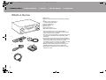
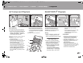
What's in the box
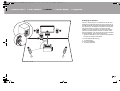
1. Main unit (1)
2. Remote controller (RC-957R) (1), Batteries (AAA/R03)
(2)
3. Speaker setup microphone (1)
0 Used during Initial Setup.
4. Indoor FM antenna (1)
5. AM loop antenna (1)
6. Power cord (1)
0 Quick Start Guide (1)
0 Basic Manual (This manual)
0 Connect speakers with 4 Ω to 16 Ω impedance.
0 The power cord must be connected only after all other
cable connections are completed.
0 We will not accept responsibility for damage arising from
the connection of equipment manufactured by other
companies.
0 Functionality may be introduced by firmware updates
and service providers may cease services, meaning that
some network services and content may become
unavailable in the future. Furthermore, available services
may vary depending on your area of residence.
0 Details on the firmware update will be posted on our
website and through other means at a later date.
0 Specifications and appearance are subject to change
without prior notice.
> Before Start > Part Names > Install > Initial Setup > Playback
1
32
54
6
SN29402813_VSX-LX302MMP_BAS_En_1703xx.book 2 ページ 2017年3月17日 金曜日 午後6時24分

3
Part Names
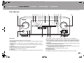
Front Panel
1. INPUT SELECTOR dial: Switch the input to be played.
2. MCACC indicator: This lights when you have enabled the speaker calibration made with
MCACC (P23).
3. FL OFF indicator: This lights when you have pressed DIMMER repeatedly to turn the
display off.
4. DIMMER button: You can switch the display off or adjust the brightness of the display in
three steps.
5. ZONE 2-ON/OFF button: Switches the multi-zone function on/off (P30).
6. ZONE 2-CONTROL button: Controls the multi-zone function (P30).
7. HOME MENU button: Displays the Home. (*)
8. Display (P4)
9. Cursor buttons ( / / / ) and ENTER button: Select the item with the cursors and
press ENTER to confirm. Use them to tune to stations when using TUNER (P28).
10.
NETWORK indicator: This lights when "NET" is selected with the input selector and the
unit is connected to the network. If the unit is in standby mode, this lights when functions
such as HDMI CEC and network standby are enabled. It does not light when ZONE 2 is
on, however.
11.
WIRELESS indicator: Lights when the unit is connected to the wireless network and when
connected to a BLUETOOTH enabled device.
12.
Remote control sensor: Receives signals from the remote controller.
0 The signal range of the remote controller is within about 16´/5 m, at an angle of 20° on
the perpendicular axis and 30° to either side.
13.
RETURN button: Returns the display to the previous state.
14.
MASTER VOLUME
15.
Í STANDBY/ON button
16.
PHONES jack: Headphones with a standard plug (Ø1/4"/6.3 mm) are connected.
> Before Start >Part Names > Install > Initial Setup > Playback
En
(*)You can find details in the Advanced Manual.
SN29402813_VSX-LX302MMP_BAS_En_1703xx.book 3 ページ 2017年3月17日 金曜日 午後6時24分

4
> Before Start >Part Names > Install > Initial Setup > Playback
17.
MCACC SETUP MIC jack: The supplied speaker setup
microphone is connected.
18.
Listening mode button: Press "AUTO/DIRECT",
"SURROUND" or "STEREO" to switch the listening
mode (P31). (*)
19.
SOUND RETRIEVER button: Turns on/off the Sound
Retriever function that provides better sound quality for
compressed audio.
20.
PURE DIRECT button: Switches to the Pure Direct
mode (P31).
21.
USB port: A USB storage device is connected so that
music files stored in it can be played. You can also
supply power (5 V/500 mA) to USB devices with a USB
cable.
22.
AUX INPUT AUDIO/HDMI jack: Connect a video
camera, etc., using a stereo mini plug cable (Ø1/8"/
3.5 mm) or a HDMI cable.
Display
1. This may light when performing operations with the "NET", "USB" input
selector.
2. Lights in the following conditions.
Z2: When ZONE 2 is on.
: When connected by BLUETOOTH.
: When connected by Wi-Fi.
NET: When "NET" is selected with the input selector and the unit is
connected to the network. It will flash if the connection to the network is
not correct.
USB: When "USB" is selected with the input selector and the unit is
connected by USB and the USB device is selected. Flashes if the USB
is not properly connected.
HDMI: When HDMI signals are input and the HDMI input is selected.
DIGITAL: When digital signals are input and the digital input is
selected.
3. Lights according to the type of input digital audio signals and the
listening mode.
4. Lights in the following conditions.
RDS: Receiving RDS broadcasting.
TUNED: Receiving AM/FM radio.
STEREO: Receiving FM stereo.
SLEEP: When the sleep timer is set.
AUTO STBY: Auto Standby is on.
5. The currently selected speaker system lights.
6. Lights when headphones are connected.
7. Flashes when muting is on.
8. Displays various information of the input signals.
9. Lights when adjusting the volume.
10.
Speaker/Channel display: Displays the output channel that
corresponds to the selected listening mode.
(*)You can find details in the Advanced Manual.
SN29402813_VSX-LX302MMP_BAS_En_1703xx.book 4 ページ 2017年3月17日 金曜日 午後6時24分

5
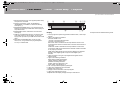
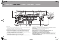
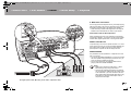
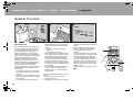
Rear Panel
1. DIGITAL AUDIO IN OPTICAL/COAXIAL jacks: Input TV or AV component digital audio
signals with a digital optical cable or digital coaxial cable.
2. ANTENNA AM LOOP/FM UNBAL 75Ω terminal: The supplied antennas are connected.
3. VIDEO IN jacks: Input the AV component video signals with an analog video cable.
4. USB port: A USB storage device is connected so that music files stored in it can be
played. You can also supply power (5 V/500 mA) to USB devices with a USB cable.
5. COMPONENT VIDEO IN jacks: Input the AV component video signals with a component
video cable. (Compatible only with 480i or 576i resolution.)
6. NETWORK port: Connect to the network with an Ethernet cable.
7. Wireless antenna: Used for Wi-Fi connection or when using a BLUETOOTH enabled
device. Adjust their angles according to the connection status.
8. HDMI OUT jacks: Transmit video signals and audio signals with a HDMI cable connected
to a monitor such as a TV or projector.
9. HDMI IN jacks: Transmit video signals and audio signals with a HDMI cable connected to
an AV component.
10.
RS-232C port: For connection to the home control system. (*)
11.
AC IN: The supplied power cord is connected.
12.
SIGNAL GND terminal: The ground wire of the turntable is connected.
13.
AUDIO IN jacks: Input AV component audio signal with an analog audio cable.
14.
SPEAKERS terminals: Connect speakers with speaker cables.
15.
ZONE 2 PRE/LINE OUT jacks: Output audio signals with an analog audio cable to a pre-
main amplifier or a power amplifier in a separate room (ZONE 2).
16.
SUBWOOFER PRE OUT jack: Connect a powered subwoofer with a subwoofer cable.
Up to two powered subwoofers can be connected. The same signal is output from each of
the SUBWOOFER PRE OUT jacks.
> Before Start >Part Names > Install > Initial Setup > Playback
180°
90°
En
(*)You can find details in the Advanced Manual.
SN29402813_VSX-LX302MMP_BAS_En_1703xx.book 5 ページ 2017年3月17日 金曜日 午後6時24分

6
> Before Start >Part Names > Install > Initial Setup > Playback
17.
IR IN/OUT port: Allows you to connect a multiroom
remote control kit. (*)
18.
12V TRIGGER OUT A/B jack: Allows you to connect a
device with 12V trigger input jack to enable link
operation between the device and the unit. (*)
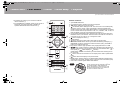
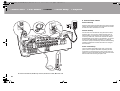
Remote Controller
1. Í STANDBY/ON button
2. Input selector buttons: Switches the input to be played.
3. 21 buttons: Select the input to be played.
4. (AV ADJUST) button: Settings such as "Tone" and "Level" can be made quickly
during play on the TV screen. "Other" has settings to switch the speakers given
priority for output (P15) and to switch HDMI output (P17). Note that there is no display
on the TV screen when the input selector is "CD", "TV", "PHONO", "AM", or "FM", so
follow the display on the main unit while doing the operations. (*)
5. Cursor buttons and ENTER button: Select the item with the cursors and press
ENTER to confirm your selection. When the folder or file lists are not shown on
one screen on the TV, press / to change the screen.
6. button: Displays the Home. (*)
7. Volume buttons
8. button: Temporarily mutes audio. Press again to cancel muting.
9. LISTENING MODE buttons: Allows you to select the listening mode (P31). (*)
MAIN/ZONE 2 buttons: Controls the multi-zone function (P30). (The ZONE 3
button is not used with this unit.)
10.
Play buttons: Used for play operations when playing Music Server or USB.
11.
button: Used for repeat or random play operations when playing Music
Server or USB. Each time you press the button, the mode switches from (1-
track repeat), to (folder repeat), to (random).
CLEAR button: Deletes all characters you have entered when entering text on
the TV screen.
12.
button: Switches the information on the display and is used to operate RDS
(P29).
13.
button: Returns the display to the previous state.
14.
MODE button: Switches tuning to an AM/FM station between automatic tuning
and manual tuning (P28), and also used to control the multi-zone feature (P30).
15.
+Fav button: Used to register AM/FM radio stations.
Tips
When the remote controller isn't working: The
remote controller may have switched to the mode
for controlling ZONE 2. While holding down
MODE, press MAIN for 3 seconds or more until
the remote indicator flashes once to switch it to
the mode to control the main room.
(*)You can find details in the Advanced Manual.
SN29402813_VSX-LX302MMP_BAS_En_1703xx.book 6 ページ 2017年3月17日 金曜日 午後6時24分

7
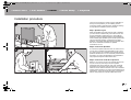
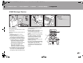
Installation procedure
This unit can be used in a number of ways, depending on
the layout of the speakers you are installing, and the
connections made to external devices. Read the following
to help make the installation process smoother.
Step1: Speaker Layout
Select the speaker layout that suits the types of speakers
you have and the conditions they will be used in from the
choices presented on pages P8 to P13, then install the
speakers by referring to the illustrations and explanations
on the relevant page. Speaker layouts include systems that
use surround back speakers, systems that use height
speakers, and systems that use Bi-Amping speakers. Also
refer to the combinations available in "Speaker
combinations" on P14.
Step2: Connect the Speakers
To connect the speaker systems to this unit, refer to P15 if
you are using a speaker layout described on one of P8 to
P12, and to P16 to use a speaker layout using Bi-Amping
speakers described on P13. The connection process will be
smoother if you refer to the illustrations and explanations
and prepare the required cables before hand.
Step3: Connect the TV & AV Components
Refer to P17 to P22 to connect your external devices such
as your TV, Blu-ray Disc Player, and also supplied
accessories such as the antennas. Also, P21 introduces
the Multi-zone Connection option that allows you to play
audio into rooms other than the main room. The connection
process will be smoother if you refer to the illustrations and
explanations, confirm the connection types on the external
devices, and prepare the required cables before hand.
> Before Start > Part Names >Install > Initial Setup > Playback
1
2 3
En
SN29402813_VSX-LX302MMP_BAS_En_1703xx.book 7 ページ 2017年3月17日 金曜日 午後6時24分

8
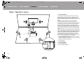
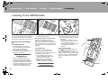
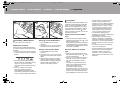
Step1: Speaker Layout
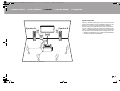
7.1 Channel System
Front speakers output front stereo sound and a center
speaker outputs center sound such as dialogs and vocals.
Surround speakers create back sound field. Powered
subwoofer reproduces bass sounds and creates rich sound
field.
This basic 5.1 Channel System with surround back
speakers added is called a 7.1 Channel System. The
connection of surround back speakers improves the sense
of envelopment and connectivity of sound created by the
back sound field and provides a more real sound field.
Furthermore, by installing surround back speakers, you can
select the Dolby Atmos listening mode, which realizes the
most up-to-date 3D sound, when the input format is Dolby
Atmos.
The front speakers should be positioned at ear height, while
the surround speakers should be positioned just above ear
height. Center speaker should be set up facing the listening
position. Placing the powered subwoofer between the
center speaker and a front speaker gives you a natural
sound even when playing music. The optimal positioning is
for surround back speakers to be at ear height.
0 If you are including surround back speakers in the setup,
surround speakers are required.
0 "Speaker combinations" (P14) introduces some detailed
examples of speaker combinations.
1,2 Front Speakers
3 Center Speaker
4,5 Surround Speakers
6 Powered Subwoofer
7,8 Surround Back Speakers
> Before Start > Part Names >Install > Initial Setup > Playback
1
2
3
½1: 22e to 30e, ½2: 90e to 110e, ½3: 135e to 150e
SN29402813_VSX-LX302MMP_BAS_En_1703xx.book 8 ページ 2017年3月17日 金曜日 午後6時24分

9
Speaker B System
With a 7.1 channel system (P8), you can connect one more
set of front speakers to use as a Speaker B System. In this
state, the 7.1 channel system becomes the Speaker A
System and you can switch the same audio to output from
A, B, or A+B. Press on the remote control (P6) and use
"Other" - "Speakers" to switch. Note that no sound is played
from the surround back speakers when playing from A+B.
0 "Speaker combinations" (P14) introduces some detailed
examples of speaker combinations.
> Before Start > Part Names >Install > Initial Setup > Playback
1
2
3
Speaker B Speaker B
½1: 22e to 30e, ½2: 90e to 110e, ½3: 135e to 150e
En
SN29402813_VSX-LX302MMP_BAS_En_1703xx.book 9 ページ 2017年3月17日 金曜日 午後6時24分

10
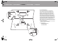
5.1.2 Channel System-1
(Front High Speakers/Rear High Speakers)
This is a basic 5.1 channel system consisting of front
speakers, a center speaker, surround speakers, and a
powered subwoofer, with the addition of front height
speakers or rear high speakers, which are both types of
height speakers. By installing height speakers, you can
select the Dolby Atmos listening mode, which realizes the
most up-to-date 3D sound including overhead sounds,
when the input format is Dolby Atmos. Front high speakers
or rear high speakers should be situated at least 3´/0.9 m
higher than the front speakers. Front high speakers should
be situated directly above the front speakers and the
distance between the rear high speakers should match the
distance between the front speakers. Both should be set up
facing the listening position.
0 "Speaker combinations" (P14) introduces some detailed
examples of speaker combinations.
9,10 Height Speakers
Choose one of the following:
0Front High Speakers
0Rear High Speakers
> Before Start > Part Names >Install > Initial Setup > Playback
1
2
3´ (0.9 m)
or more
3´ (0.9 m)
or more
½1: 22e to 30e, ½2: 120e
SN29402813_VSX-LX302MMP_BAS_En_1703xx.book 10 ページ 2017年3月17日 金曜日 午後6時24分

11
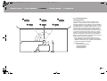
5.1.2 Channel System-2
(Ceiling Speakers)
This is a basic 5.1 channel system consisting of front
speakers, a center speaker, surround speakers, and a
powered subwoofer, with the addition of top front speakers,
top middle speakers, or top rear speakers, which are types
of height speakers. By installing height speakers, you can
select the Dolby Atmos listening mode, which realizes the
most up-to-date 3D sound including overhead sounds,
when the input format is Dolby Atmos. Fit top front speakers
on the ceiling forward of the seating position, top middle
speakers on the ceiling directly above the seating position,
and top rear speakers on the ceiling behind the seating
position. The distance between each pair should match the
distance between the two front speakers.
0 Dolby Laboratories recommends placing this type of
height speakers to obtain the best Dolby Atmos effect.
0 "Speaker combinations" (P14) introduces some detailed
examples of speaker combinations.
9,10 Height Speakers
Choose one of the following:
0Top Front Speakers
0Top Middle Speakers
0Top Rear Speakers
> Before Start > Part Names >Install > Initial Setup > Playback
1
2
3
½1: 30e to 55e, ½2: 65e to 100e, ½3: 125e to 150e
En
SN29402813_VSX-LX302MMP_BAS_En_1703xx.book 11 ページ 2017年3月17日 金曜日 午後6時24分

12
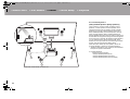
5.1.2 Channel System-3
(Dolby Enabled Speakers (Dolby Speakers))
This is a basic 5.1 channel system consisting of front
speakers, a center speaker, surround speakers, and a
powered subwoofer, with the addition of Dolby enabled
speakers (front), Dolby enabled speakers (surround) or
Dolby enabled speakers (surround back) which are both
types of height speakers. Dolby enabled speakers are
special speakers designed to face the ceiling so that sound
is heard after bouncing off the ceiling so that sound appears
to be coming from overhead. By installing height speakers,
you can select the Dolby Atmos listening mode, which
realizes the most up-to-date 3D sound including overhead
sounds, when the input format is Dolby Atmos.
Place them either above the front speakers, above the
surround speakers or above surround back speakers.
0 "Speaker combinations" (P14) introduces some detailed
examples of speaker combinations.
9,10 Height Speakers
Choose one of the following:
0 Dolby Enabled Speakers (Front)
0 Dolby Enabled Speakers (Surround)
0 Dolby Enabled Speakers (Surround Back)
> Before Start > Part Names >Install > Initial Setup > Playback
1
2
3
½1: 22e to 30e, ½2: 90e to 120e, ½3: 135e to 150e
SN29402813_VSX-LX302MMP_BAS_En_1703xx.book 12 ページ 2017年3月17日 金曜日 午後6時24分

13
Bi-Amping the Speakers
With a 5.1 channel system, it is possible to connect front
speakers that support Bi-Amping to improve the quality of
the bass and treble. Bi-Amping compatible speakers need
their terminals for the tweeters connected to one amplifier
and their terminals for woofers connected to another
amplifier, so it is not possible to connect height speakers
and surround back speakers with this connection. Other
than front speakers, you can also connect a center speaker,
surround speakers, and a powered subwoofer.
0 "Speaker combinations" (P14) introduces some detailed
examples of speaker combinations.
1,2 Front Speakers (Bi-Amping)
3 Center Speaker
4,5 Surround Speakers
6 Powered Subwoofer
> Before Start > Part Names >Install > Initial Setup > Playback
1
2
½1: 22e to 30e, ½2: 120e
En
SN29402813_VSX-LX302MMP_BAS_En_1703xx.book 13 ページ 2017年3月17日 金曜日 午後6時24分

14
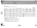
Speaker combinations
0 In any of the combinations, up to two powered subwoofers can be connected.
(*1) You can select one of Speaker B, Bi-AMP, or ZONE SPEAKER.
(*2) When using Speakers B, no sound is played from the surround back speakers when
playing from A+B.
(*3) No sound is played from the height speakers when playing audio from ZONE
SPEAKER.
(*4) You can connect both surround back speakers and height speakers. However, you can
only output audio from one of these at a time. When both are connected, you can set
which speakers to prioritize.
0 Press on the remote control (P6) and use "Other" - "Speakers" to switch speakers A
and B and to switch between surround back speakers and height speakers.
> Before Start > Part Names >Install > Initial Setup > Playback
Speaker Channels FRONT CENTER SURROUND
SURROUND
BACK HEIGHT
SP B
(Speaker B)
Bi-AMP
ZONE 2
(ZONE SPEAKER)
(P21)
2.1 ch
(*1) (*1) (*1)
3.1 ch
(*1) (*1) (*1)
4.1 ch
(*1) (*1) (*1)
5.1 ch
(*1) (*1) (*1)
6.1 ch
(*2)
7.1 ch
(*2)
2.1.2 ch
(*3)
3.1.2 ch
(*3)
4.1.2 ch
(*3)
5.1.2 ch
(*3)
6.1.2 ch
(*4) (*4)
7.1.2 ch
(*4) (*4)
SN29402813_VSX-LX302MMP_BAS_En_1703xx.book 14 ページ 2017年3月17日 金曜日 午後6時24分

15
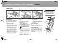
Step2: Connect the Speakers
Standard Connections (Pages 8 to 12)
Connect 12345678 for a 7.1 channel system.
Connect 1234569: for a 5.1.2 channel system. Up
to two powered subwoofers can be connected. The same
signal is output from each of the SUBWOOFER PRE OUT
jacks.
0
You can also connect both
78
and
9:
. However, you can
only output audio from one of these at a time. When both
are connected, you can switch which speakers to prioritize.
Press on the remote control (P6) and use "Other" -
"Speakers" to switch between surround back speakers and
height speakers and to switch speakers A and B.
Make sure the exposed wires of the speakers do
not stick out of the speaker terminals when
connecting. If the exposed wires of the speakers
touch the rear panel or the + and – wires touch
each other, the protection circuit will be activated.
> Before Start > Part Names >Install > Initial Setup > Playback
a
b
OR
Speaker B
1/2˝
(12 mm)
a Speaker cable, b Subwoofer cable
Setup
0 Settings for the speaker configuration you have
connected need to be made in "1. Full Auto
MCACC" in Initial Setup (P23).
0
If any of the connected speakers have an impedance of
4 Ω or more to less than 6 Ω, after completing Initial
Setup, you need to make some settings in the System
Setup menu. Press on the remote controller, and in
the Home displayed set "System Setup" - "Speaker" -
"Configuration" - "Speaker Impedance" to "4ohms".
En
SN29402813_VSX-LX302MMP_BAS_En_1703xx.book 15 ページ 2017年3月17日 金曜日 午後6時24分

16
Connecting with Bi-Amping Speakers (Page 13)
Make sure you remove the jumper bar fitted between the
woofer jacks and tweeter jacks of the front speakers.
Refer
to "Standard Connections (Pages 8 to 12)" (P15) to connect
the center speaker, surround speakers, and powered
subwoofer.
0 Also refer to the instruction manual for your speakers
when using connections for Bi-Amping.
Make sure the exposed wires of the speakers
do not stick out of the speaker terminals when
connecting. If the exposed wires of the
speakers touch the rear panel or the + and –
wires touch each other, the protection circuit
will be activated.
> Before Start > Part Names >Install > Initial Setup > Playback
a
1/2˝
(12 mm)
For high-
frequency
For low-
frequency
a Speaker cable
Setup
0 Settings for the speaker configuration you have
connected need to be made in "1. Full Auto
MCACC" in Initial Setup (P23).
0 If any of the connected speakers have an
impedance of 4 Ω or more to less than 6 Ω, after
completing Initial Setup, you need to make some
settings in the System Setup menu. Press on
the remote controller, and in the Home displayed
set "System Setup" - "Speaker" - "Configuration" -
"Speaker Impedance" to "4ohms".
SN29402813_VSX-LX302MMP_BAS_En_1703xx.book 16 ページ 2017年3月17日 金曜日 午後6時24分

17
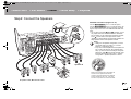
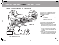
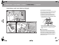
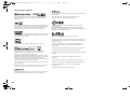
Step3: Connect the TV & AV Components
1. Connect the TV
To ARC TV
For a TV that supports the ARC (Audio Return Channel)
feature (*1), use an HDMI cable and connect according to
illustration "a". Choose an HDMI IN jack on the TV that
supports ARC when connecting.
To Non-ARC TV
For a TV that does not support the ARC (Audio Return
Channel) feature (*1), connect both the HDMI cable in
illustration "a" and the digital optical cable in "b".
0 Connection with a digital optical cable is not necessary if
you will watch TV through a device such as a cable set-
top box (that is, not use a tuner built into the TV) that you
have connected to the input jack on this unit.
(*1) The ARC feature: This feature transfers TV audio
signals via HDMI cable so that you can play the audio
from the TV through this unit. Connection to an ARC
compatible TV is complete with one HDMI cable. Refer
to the instruction manual for your TV to see if it
supports ARC.
(*2) Another TV or projector can be connected to the HDMI
OUT SUB jack. Press (P6) on the remote control
and use "Other" - "HDMI Out" to switch between MAIN
and SUB. Note that this jack does not support ARC.
> Before Start > Part Names >Install > Initial Setup > Playback
TV
*2
a
b
a HDMI cable, b Digital optical cable
Setup
0 Settings are required to use the ARC function.
Select "Yes" in "5. Audio Return Channel" (P24)
in the Initial Setup.
0 Refer to the instruction manual for the TV for TV
connections and instructions regarding settings
for CEC features and audio output.
En
SN29402813_VSX-LX302MMP_BAS_En_1703xx.book 17 ページ 2017年3月17日 金曜日 午後6時24分

18
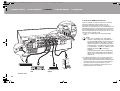
2. Connect the HDMI AV Component
This is an example of connection with an AV component
that has an HDMI jack. With connection to an AV
component that conforms with the CEC (Consumer
Electronics Control) standard, you can use features such as
the HDMI CEC feature (*) that links with the input selector,
and the HDMI Standby Through feature which allows you to
play video and audio from AV components on the TV even
when this unit is in standby mode.
0 To play 4K or 1080p video, use a high speed HDMI
cable.
(*)The HDMI CEC feature: You can control features such
as linking input switching with the input selector and
players conforming to the CEC standard, switching audio
to output it from the TV or from this unit, and adjusting
the volume using the remote controller of a CEC-
compliant TV, and automatically switching this unit to
standby when the TV is turned off.
> Before Start > Part Names >Install > Initial Setup > Playback
BD/DVD
GAME
a
Cable/Satellite set-top
box
Streaming media
player
a HDMI cable
Setup
0 When "Yes" is selected for "5. Audio Return
Channel" in Initial Setup (P24), the HDMI CEC
function and HDMI Standby Through function are
automatically enabled. If "No, Skip" is selected,
settings are required in the System Setup menu
after Initial Setup is complete. Settings are made
in "System Setup" - "Hardware" - "HDMI" in Home
displayed by pressing on the remote
controller.
0 To enjoy digital surround sound including Dolby
Digital, audio output should be set to "Bitstream
output" on the connected Blu-ray Disc player or
other device.
SN29402813_VSX-LX302MMP_BAS_En_1703xx.book 18 ページ 2017年3月17日 金曜日 午後6時24分

19
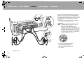
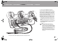
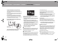
3. Connect the Non-HDMI AV Component
This is an example of connection with an AV component
that does not have an HDMI jack. Make the connections to
the AV component to match the jacks it has. When video
input connection is to the BD/DVD jack, the audio input
connection should also be to the BD/DVD jacks, and so on,
so that you connect the video input jacks to the jacks with
the same name as the audio input jacks.
Note that video signals input to the VIDEO IN jack or the
COMPONENT VIDEO IN jack will be converted to HDMI
video signals and then output from the HDMI OUT jack.
0 To enjoy digital surround playback in formats such as
Dolby Digital, you need to make a connection for audio
signals with a digital coaxial cable or a digital optical
cable.
0 It is possible to change assignment of the input jacks you
see in the illustration at left, so you can also connect to
any jack other than BD/DVD. For details, see the
Advanced Manual.
> Before Start > Part Names >Install > Initial Setup > Playback
BD/DVD
OR
a
b
c
a Component video cable, b Digital optical cable, c Analog audio cable
Setup
0 The COMPONENT VIDEO IN jacks are
compatible only with 480i or 576i resolution.
When you connect to the COMPONENT VIDEO
IN jacks, set the output resolution of the player to
480i or 576i. Select interlace if there is no option
for 480i, etc. If your player does not support 480i
or 576i output, use the VIDEO IN jack.
0 To enjoy digital surround sound including Dolby
Digital, audio output should be set to "Bitstream
output" on the connected Blu-ray Disc player or
other device.
En
SN29402813_VSX-LX302MMP_BAS_En_1703xx.book 19 ページ 2017年3月17日 金曜日 午後6時24分

20
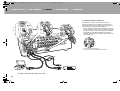
4. Connect the Audio Component
Example of a connection with an audio component.
Connect a CD player using a digital coaxial cable or an
analog audio cable. You can also connect a turntable that
has an MM-type cartridge to the PHONO jack.
0 If the turntable has a built-in audio equalizer, connect it to
another AUDIO IN jack. Further, if the turntable uses an
MC type cartridge, install an audio equalizer compatible
with the MC type cartridge between the unit and the
turntable, then connect to any AUDIO IN jack other than
the PHONO jack.
If the turntable has a ground wire,
connect it to the SIGNAL GND terminal of this unit.
> Before Start > Part Names >Install > Initial Setup > Playback
CD
OR
a
b
Turntable
a Digital coaxial cable, b Analog audio cable
SN29402813_VSX-LX302MMP_BAS_En_1703xx.book 20 ページ 2017年3月17日 金曜日 午後6時24分
Page is loading ...
Page is loading ...
Page is loading ...
Page is loading ...
Page is loading ...
Page is loading ...
Page is loading ...
Page is loading ...
Page is loading ...
Page is loading ...
Page is loading ...
Page is loading ...
Page is loading ...
Page is loading ...
Page is loading ...
Page is loading ...
-
 1
1
-
 2
2
-
 3
3
-
 4
4
-
 5
5
-
 6
6
-
 7
7
-
 8
8
-
 9
9
-
 10
10
-
 11
11
-
 12
12
-
 13
13
-
 14
14
-
 15
15
-
 16
16
-
 17
17
-
 18
18
-
 19
19
-
 20
20
-
 21
21
-
 22
22
-
 23
23
-
 24
24
-
 25
25
-
 26
26
-
 27
27
-
 28
28
-
 29
29
-
 30
30
-
 31
31
-
 32
32
-
 33
33
-
 34
34
-
 35
35
-
 36
36


Pioneer VSX 924 Owner's manual
- Category
- Receiver
- Type
- Owner's manual
- This manual is also suitable for
Ask a question and I''ll find the answer in the document
Finding information in a document is now easier with AI
Related papers
-
Pioneer VSX-LX102 Owner's manual
-
Pioneer VSX-LX303 Owner's manual
-
Pioneer VSX-LX302 Owner's manual
-
-
Pioneer VSX-1131 User manual
-
Pioneer SC-LX501 Advanced Manual
-
-
-
Pioneer VSX-832 User manual
-
Other documents
-
ONKYO TX-RZ3100 Owner's manual
-
ONKYO TX-RZ1100 Owner's manual
-
Integra DRX-3.2 Owner's manual
-
Integra DRX-R1.1 User manual
-
-
ONKYO TX-RZ830TXRZ830TXRZ830 Owner's manual
-
ONKYO PR-RZ5100 Owner's manual
-
-
ONKYO TX-RZ730 Owner's manual
-
ONKYO TX-RZ820 Owner's manual