Page is loading ...

PLEASE READ ALL OF THE OWNERS MANUAL AND SAFETY NOTES
IMPORTANT SAFETY NOTES:
1. When installing your stove, particular attention should be paid to fire protection. If this unit is not properly installed, a
house fire may result. For your safety, follow the installation instructions and contact local building or fire officials
about restrictions and installation inspection requirements in your area.
2. Never use gasoline or similar liquids to start a fire in this unit. Keep all such liquids well away from stove.
3. During operation, if any part of the stove starts to glow, the stove is in an overfired condition. Close the air controls
completely until the glowing has stopped. OVERFIRING VOIDS WARRANTY.
4. Cool ashes should be disposed of carefully, using a metal container.
5. Do not burn wet or green wood. Store wood in dry location.
6. Do not burn garbage, treated wood, or wood with salt (driftwood, etc.). Burning materials other than wood (including
charcoal) under adverse conditions may generate carbon monoxide in the home, resulting in illness or possible death.
7. Do not permit creosote or soot to accumulate excessively in the chimney or inside the firebox.
8. Check your chimney system thoroughly when installing into an existing metal or masonry chimney. Seek professional
advice if in doubt about its condition.
9. Do not connect this unit to a chimney flue already serving another appliance.
10. Comply with all minimum clearances to combustibles as shown in this manual for this appliance.
11. Build fire on brick firebox floor. Do not use grates, andirons or other method to support fuel.
12. HOT WHILE IN OPERATION. Keep children, pets, clothing and furniture away. Contact can cause skin burns.
13. Do not connect to any air distribution duct or system.
14. RISK OF FIRE! Do not operate with stove door or ash removal system door open.
15. For further information refer to NFPA 211 (U.S.) or CAN/CSA-B365 (Canada).
16. WARNING: WHEN ASSEMBLING A UNIBODY APPLIANCE, USE ONLY GENUINE ALADDIN HEARTH
PRODUCTS MANUFACTURED COMPONENTS. USE OF ANY OTHER COMPONENTS WILL VOID YOUR
WARRANTY, AND COULD PRESENT A SERIOUS SAFETY HAZARD.
17. WARNING: DO NOT OPERATE YOUR QUADRA-FIRE STOVE BEFORE FULLY ASSEMBLING ALL
COMPONENTS. BURNING YOUR STOVE WITHOUT A PEDESTAL OR LEG KIT ATTACHED WILL VOID
YOUR WARRANTY, AND COULD PRESENT A SERIOUS SAFETY HAZARD. (Revised 01/1999)
INSTALLATION, OPERATION, AND MAINTENANCE INSTRUCTIONS
QUADRA-FIRE 3100 SERIES
www.aladdinhearth.com
401 N. WYNNE
COLVILLE, WA 99114
North America’s Best
SAVE THESE INSTRUCTIONS
CONGRATULATIONS—You are now the proud owner of one of the finest stoves in the world for your home —the
QUADRA-FIRE. Now, before installing your stove and building your first fire—record the serial number on the
warranty card. Serial number is located on the safety label on the rear of the stove.
Part #250-3500 #832-3050

TABLE OF CONTENTS
Safety label ......................................................................................................................................... 3
Dimensions......................................................................................................................................... 4
Clearances to combustibles ................................................................................................................ 6
Safety listing....................................................................................................................................... 7
Installation materials needed .............................................................................................................. 7
Venting system ................................................................................................................................... 7
Chimney connector ............................................................................................................................ 8
Chimney height/draft.......................................................................................................................... 8
Connection to a masonry chimney ..................................................................................................... 8
1. Chimney.................................................................................................................................. 8
2. Thimble................................................................................................................................... 11
A. Brick chimney thimble assembly .....................................................................................11
B. 6" solid pack chimney with metal supports ...................................................................... 12
Connection to a metal prefabricated chimney ....................................................................................14
Mobile home installation.................................................................................................................... 15
Outside air kit installation .................................................................................................................. 16
Pedestal and leg installation ...............................................................................................................17
Ash removal system installation ........................................................................................................18
Ash removal system operating and cleaning...................................................................................... 19
Operating instructions ........................................................................................................................ 20
Burning process .......................................................................................................................... 20
Primary and secondary air systems............................................................................................. 20
Blower operating instructions..................................................................................................... 21
Operating tips.............................................................................................................................. 21
Burning guidelines...................................................................................................................... 21
Building a fire .............................................................................................................................22
Wood selection and storage ........................................................................................................ 22
Maintenance ....................................................................................................................................... 23
Creosote ...................................................................................................................................... 23
Care and cleaning of glass and plated surfaces...........................................................................23
Chimney cleaning ....................................................................................................................... 23
Ash removal................................................................................................................................ 23
Firebrick...................................................................................................................................... 23
Overfiring.................................................................................................................................... 23
Door handle assembly and glass replacement.................................................................................... 24
Baffle removal and installation .......................................................................................................... 25
Brick pattern ....................................................................................................................................... 26
Installation of optional blower ........................................................................................................... 27
Top heat shield installation ................................................................................................................ 28
Accessories and service parts ............................................................................................................. 29
Notes ............................................................................................................................................... 30
Warranty............................................................................................................................................. 31
Warranty card ..................................................................................................................................... Insert
Page 2

3100 SAFETY LABEL
(found on back of stove)
Page 3
Manufactaured by:
Model:
Quadra-Fire
3100
Serial No.

24 1/2" (622mm)
9" (229mm)
21 1/2" (546mm)
2 1/4" (57mm)
23" (584mm)
DIMENSIONS
Page 4
FIGURE 1b
FIGURE 1a
20 1/2" (521mm)
9" (229mm)
24 1/2" (622mm)
2 1/4" (57mm)
23" (584mm)
26 3/8" (670mm)
LEG MODEL
PEDESTAL MODEL

DIMENSIONS
Page 5
26 5/8" (676mm)
23 7/8" (606mm)
13 11/16" (348mm)
4 5/16" (110mm)
24 5/8" (626mm)
25" (635mm)
9" (229mm)
2 13/16" (72mm)
21 1/2 (546mm)
STEP TOP LEG MODEL
13 11/16" (348mm)
4 5/16" (110mm)
26 5/8" (676mm)
23 7/8" (606mm)
2 13/16" (72mm)
24 5/8" (626mm)
20 1/2" (521mm)
21" (533mm)
9" (229mm)
STEP TOP PEDESTAL MODEL
FIGURE 2b
FIGURE 2a

Minimum clearances to Combustible Materials (in inches and millimeters) for Quadra-Fire 3100 Standard Stove
Chimney &
Installation Clearance Connector A B C D E F
Residential Standard Note 1 14”(356) 26”(661) 18”(457) 12”(305) 18”(457) 10”(254)
Residential/Mobile Home Reduced Note 2 12”(305) 26”(661) 16”(406) 10”(254) 18”(457) 8”(203)
Alcove Standard Note 2 & 3 12”(305) 26”(661) N/A 10”(254) 18”(457) 8”(203)
Minimum clearances to Combustible Materials (in inches and millimeters) for Quadra-Fire 3100 with top shield
Chimney &
Installation Clearance Connector A B C D E F
Residential Standard Note 1 12”(305) 24”(610) 16”(406) 10”(254) 16”(406) 8”(203)
Residential/Mobile Home Reduced Note 2 10”(254) 24”(610) 14”(356) 8”(203) 16”(406) 6”(153)
Alcove Standard Note 2 & 3 10”(254) 24”(610) N/A 8”(203) 16”(406) 6”(153)
Minimum clearances to Combustible Materials (in inches and millimeters) for Quadra-Fire 3100 Step Top Stove
Chimney &
Installation Clearances Connector A B C D E F
Residential Standard Note 1 12”(305) 24”(610) 16”(406) 10”(254) 16”(406) 8”(203)
Residential/Mobile Home Reduced Note 2 10”(254) 24”(610) 14”(356) 8”(203) 16”(406) 6”(153)
Alcove Standard Note 2 & 3 10”(254) 24”(610) N/A 8”(203) 16”(406) 6”(153)
Note 1: 6” (152mm) diameter single wall, minimum 24 MSG black or blued steel connector pipe with a listed factory-built type HT
chimney suitable for use with solid fuels or a masonry chimney.
Note 2: 6” (152mm) diameter double wall insulated connector pipe with listed factory-built type HT chimney or a masonry chimney.
(Mobile home venting system must be equipped with a rain cap and spark arrestor.) For installations with a preexisting class A
chimney system, a listed stainless steel chimney liner should be installed, or the existing chimney examined by a chimney sweep for
acceptable further use.
Note 3: Alcove specifications: Maximum depth of alcove shall be no more than 48” (1219mm). For additional alcove information
and clearances, refer to clearances to combustibles above.
NOTE: Unit is approved for use with listed double wall air-insulated chimney connector or elbows.
When locating your stove consider safety, convenience, traffic flow, and the fact that the stove will need a chimney and chimney
connector.
FLOOR PROTECTION: Floor protector must be noncombustible material, extending beneath heater and to the front/sides/rear as
indicated.
NOTE: A 3/8” (10mm) minimum thickness tile or equivalent is recommended, but not required.
NFPA 211: Use a noncombustible material with 1” (25mm) ventilated air space to reduce clearances. However, this is not to exceed
50% of Quadra-Fire’s specified clearances.
NOTE: Must follow NFPA 211 spacing and materials to qualify. It is also subject to local jurisdiction.
AVOID FIRE: Maintain the designated clearances to combustibles. Insulation must not touch the chimney. You must maintain the
designated air space clearance around the chimney. This space around a chimney is necessary to allow natural heat removal from the
area. Insulation in this space will cause a heat buildup, which may ignite wood framing.
CLEARANCES TO COMBUSTIBLES (UL AND ULC)
Page 6
FLOOR PROTECTION: Floor
protector must be noncombustible
material or equivalent, extending
beneath heater and to the front/
sides/rear as indicated.
NOTE: A 3/8” (10mm) minimum
thickness tile or equivalent is
recommended, but not required.

SAFETY LISTING
The Quadra-Fire 3100 is listed by OMNI-Test Laboratories, Inc. , Beaverton, Oregon, to UL 1482-83, (UM)84
HUD and ULC S627. It is also approved for mobile home installations with outside combustion air in the U.S.
(see pages 15 and 16 for further details). For residential installations in Canada without an outside combustion
air kit, a source of fresh air into the room must be provided.
INSTALLATION MATERIALS NEEDED FOR YOUR SAFETY
CHIMNEY CONNECTOR (also known as flue pipe or stove pipe): The chimney connector joins the stove to
the chimney (see page 8). It should be 6” (152mm) minimum diameter 24 MSG black or blued steel, or an
approved air-insulated double wall venting pipe.
THIMBLE: A manufactured or site-constructed device installed in combustible walls through which the
chimney connector passes to the chimney (see page 11-13). It is intended to keep the walls from igniting.
CHIMNEY SYSTEMS:
A. APPROVED MASONRY (see specifications on pages 8-13) with at least 5/8” (16mm) fire clay lining
joined with refractory cement or other listed system suitable for use with wood stoves.
B. PREFABRICATED 6" (152mm) listed high temperature (UL 103HT or ULC 629M) chimney. Components
required by manufacturers for installation such as the chimney support base, firestop (as appropriate), attic
insulation shield, insulated tee, etc., are necessary to assure a safe chimney installation. Use only
components manufactured for the chimney. Chimney installation should meet NFPA 211 standards.
FIRE SAFETY: To provide reasonable fire safety, the following should be given serious consideration:
1. Install at least one smoke detector on each floor of your home to ensure your safety. They should be
located away from the heating appliance and close to the sleeping areas. Follow the smoke detector
manufacturer’s placement and installation instructions, and be sure to maintain regularly.
2. A conveniently located Class A fire extinguisher to contend with small fires resulting from burning embers.
3. A practiced evacuation plan, consisting of at least two escape routes.
4. A plan to deal with a chimney fire as follows:
In the event of a chimney fire:
A. Notify fire department
B. Prepare occupants for immediate evacuation.
C. Close all openings into the stove.
D. While awaiting fire department, watch for ignition of adjacent combustibles from overheated stove pipe,
hot embers or sparks from the chimney.
VENTING SYSTEM
The venting system consists of a chimney connector and a chimney. These get extremely hot during use.
Temperatures inside the chimney may exceed 2000°F (1100°C) in the event of a creosote fire. To protect
against the possibility of a house fire, the chimney connector and chimney must be properly installed and
maintained. An approved thimble must be used when a connection is made through a combustible wall to a
chimney. A chimney support package must be used when a connection is made through the ceiling to a
prefabricated chimney. These accessories are absolutely necessary to provide safe clearances to combustible
wall and ceiling material. Follow venting manufacturer’s clearances when installing venting system.
This stove may be connected to a lined masonry chimney or a listed high temperature prefabricated approved
metal chimney. Do not connect it to a chimney serving another appliance. To do so will affect the safe
operation of both appliances.
Page 7

CHIMNEY CONNECTOR
The chimney connector must be 6” (152mm) diameter with a minimum thickness of 24 gauge. Do not use
aluminum or galvanized steel. They cannot properly withstand the extreme temperatures of a wood fire. Do not
use chimney connector pipe as a chimney. You must connect your stove to a chimney comparable to those
illustrated in this manual.
Chimney connector sections must be attached to the stove and to each other with the crimped end toward the
stove (Figure 3). This allows creosote to run into the stove and not onto the outside of the pipe. Attach the
chimney connector to the flue collar with three sheet metal screws. All joints should also be secured with three
sheet metal screws. Otherwise, in the event of a creosote fire, the connector may vibrate apart.
For proper operation, the chimney connector should be as short as possible. Horizontal lengths of chimney
connector should have a minimum upward slope from the stove of at least ¼” per foot.
CHIMNEY HEIGHT/DRAFT
To insure that your Quadra-Fire stove burns properly, the chimney draft (static pressure) should be
approximately 0.1” water column (W.C.) during a high burn and .04” W.C. during a low burn, measured 6”
(152mm) above the top of the stove after one hour of operation at each burn setting.
NOTE: These are guidelines only, and may vary somewhat for individual installations.
Your Quadra-Fire stove was designed for and tested on a 6” (152mm) chimney, 12’-14’ (3.66-4.27m) high,
measured from the top of the stove. The further your stack height or diameter varies from this configuration,
the probability of performance problems increases. In addition, exterior conditions such as roof line,
surrounding trees, prevailing winds and nearby hills can influence stove performance.
CONNECTION TO A MASONRY CHIMNEY
1. CHIMNEY: Should the stove be connected to a masonry chimney, the chimney should be examined for
cracks, loose mortar, or other signs of deterioration and blockage. The stove should not be installed until it
is determined that the chimney is safe for use. Since an oversized flue contributes to the accumulation of
creosote, the size of the flue should be checked to determine that it is not too large for the stove. The
chimney should also be checked to insure it meets the minimum standards of the National Fire Protection
Association (NFPA) Standard 211. Following is a list of the more critical minimum requirements for a
properly constructed chimney.
The masonry wall of the chimney, if brick or modular block, must be a minimum of 4” (102mm) thick. A
mountain or rubble stone wall must be at least 12” (305mm) thick.
Page 8
FIGURE 3

A chimney inside the house must have at least 2” (50mm) of clearance to the combustible structure. A chimney
outside the house must have at least 1” (25mm) clearance to the combustible structure. Firestops must be
installed in the spaces where the chimney passes through floors and/or ceiling (Figure 5).
The chimney must have a fire clay flue liner (or equivalent) with a minimum thickness of 5/8” (16mm) and
must be installed with refractory mortar. There must be at least ½” (13mm) air space between the flue liner and
the chimney wall (Figure 4). An equivalent liner must be a listed chimney liner system or other approved
material.
Page 9
FIGURE 4
FIGURE 5

A chimney must be the required height above the roof or other obstruction for safety and proper draft operation.
The chimney must be a minimum of 3’ (914mm) higher than the highest point where it passes through the roof,
and at least 2’ (610mm) higher than the highest part of the roof or structure that is within 10’ (3048mm) of the
chimney, measured horizontally (Figure 7).
Remember that insulation must not contact the chimney. There must be air space around the chimney.
Insulation must be 2” (50mm) or more from the chimney (Figure 6).
Page 10
FIGURE 6
FIGURE 7

2. THIMBLE: An approved thimble must be used when the connection from the stove is made through a
combustible wall to a masonry chimney. There are several methods you can use for connection through a
combustible wall, two of which are illustrated in this manual. For additional methods, consult local building
authorities or use the standards set forth in NFPA 211.
Also, listed prefabricated metal thimbles are available for use with wood stoves. The manufacturer’s
installation for the thimbles must be strictly followed to assure the safety of the system. Be sure to maintain
the designated clearances to combustible materials.
A. BRICK CHIMNEY THIMBLE ASSEMBLY: Construction of the brick thimble assembly requires
12” (305mm) of brick around a fire clay liner. Be sure the point of penetration allows an 18” (457mm)
clearance from the connector to the ceiling. For a 6” (152mm) chimney connector, an opening of 30”
(762mm) must be cut in the wall to maintain the required 12” (305mm) of brick separation from
combustibles. It will be necessary to cut wall studs and install a header and sill frame to maintain proper
dimensions and to hold the weight of the brick (Figure 8).
Page 11
FIGURE 8

Minimum 3 ½” (89mm) [4” (102mm) nominal] thick solid bricks are to be used. The fire clay liner
(ASTM C35 or equivalent), 5/8” (16mm) wall thickness, must not penetrate into the chimney beyond the
inner surface of the chimney flue liner and must be firmly cemented in place. If it is necessary to cut a
hole in the chimney liner, use extreme care to keep it from shattering. Refractory mortar must be used at
the junction with the chimney liner. After the assembly is complete, insert the chimney connector into
the fire clay liner. Do not push it beyond the inside edge of the chimney liner, as this will affect the
draw of the chimney.
B. 6” SOLID PACK CHIMNEY WITH METAL SUPPORTS AS A THIMBLE: For the method of
installation to a masonry chimney shown in Figures 10 and 11 (page 13), it will be necessary to purchase
a 6” (152mm) inside diameter, 12” (305mm) long section of prefabricated listed solid pack chimney to
use as a thimble. Purchase a wall spacer, trim collar and wall band that are manufactured to fit the
chimney section you purchase. Cut out a 14 ½” (368mm) diameter opening in the wall. It may be
necessary to cut wall studs and install a header and sill frame to maintain the wall support. The hole in
the chimney must have at least a 6” (152mm) diameter fire clay liner or equivalent, secured with
refractory mortar. If it is necessary to cut a hole in the chimney liner, use extreme care to keep it from
shattering.
The safety features of this system are the 2” (50mm) air space between the chimney section and
combustible wall, and the 1” (25mm) air space around the chimney connector as it passes through the
chimney section to the chimney. The location of the opening through the wall to the chimney must
leave a minimum 18” (457mm) vertical clearance between the connector pipe and the ceiling, to prevent
the ceiling from catching fire when using single wall pipe.
Page 12
FIGURE 9

First, build the frame for the thimble, making sure that it is no smaller than 14½” (368mm) diameter, which will
maintain a 2” (50mm) air space around the chimney section. Attach the wall spacer to the chimney side of the
frame. Then insert the frame into the opening, toe-nailing it to the wall studs. Install the wall band in the
framing to secure the chimney section in place. Insert a single section of chimney connector into the chimney
through the wall band, being sure it does not protrude into the chimney beyond the edge of the chimney flue
lining. Apply high temperature furnace cement to the end of the chimney section and install it over the
connector, through the wall band, and through the wall spacer. Tighten the wall band to hold the chimney
section firmly in place and against the chimney. Install the trim collar on the outside of the opening. Check to
insure there is a 1” (25mm) air space between the connector and the chimney section. Also, during installation,
always check to insure that a 2” (50mm) air space is being maintained to the wood framing. Do not fill this
space with insulation. Insulation in this air space will cause a heat buildup which may ignite the wood framing.
Page 13
FIGURE 10
FIGURE 11

CONNECTION TO A METAL PREFABRICATED CHIMNEY
When a metal prefabricated chimney is used, the manufacturer’s installation instructions must be followed
precisely. You must also purchase (from the same manufacturer) and install the ceiling support package or wall
pass-through and “T” section package, firestops (where needed), insulation shield, roof flashing, chimney cap,
etc. Maintain the proper clearance to the structure as recommended by the manufacturer. This clearance is
usually a minimum of 2” (50mm), although it may vary by manufacturer or for certain components.
There are basically two methods of metal chimney installation. One method is to install the chimney inside the
residence through the ceiling and the roof (Figure 12). The other method is to install an exterior chimney that
runs up the outside of the residence (Figure 13). This method of installation requires at a minimum a wall pass-
through device, a wall support package, insulated “T” section and roof flashing. The components illustrated
may not look exactly like the system you purchase, but they demonstrate the basic components you will need
for a proper and safe installation.
The chimney must be the required height above the roof or other obstruction for safety and proper draft
operation. The chimney must be a minimum of 3’ (914mm) higher than the highest point where it passes
through the roof, and at least 2’ (610mm) higher than the highest part of the roof or structure that is within 10’
(3048mm) of the chimney, measured horizontally (Figure 5, on page 9).
REMEMBER: Follow the manufacturer’s installation instructions and maintain the manufacturer’s specified
clearance distances.
Page 14
FIGURE 12
INTERIOR CHIMNEY, RUNNING
THROUGH
CEILING AND ROOF

MOBILE HOME INSTALLATION
You must use a Quadra-Fire 3100 outside air kit (see page 16 for part numbers) for installation in a mobile
home. Use of alternative material will void warranty.
1. An outside air inlet must be provided for combustion and be unrestricted while unit is in use.
2. Unit must be secured to the mobile home structure by bolting pedestal through hearth pad and into floor.
For leg models, use attachment brackets to attach stove through pad and into floor.
3. Do not install unit in a sleeping room.
4. The structural integrity of the mobile home floor, walls, and ceiling/roof must be maintained (i.e., do not
cut through floor joist, wall stud, ceiling truss, etc.).
5. Unit must be grounded with #8 copper grounding wire or equivalent and terminated at each end with
N.E.C. approved grounding device.
6. Refer to clearance to combustibles section (page 6) for listing to combustibles.
7. Seal all wall/floor inlets to prevent air or moisture penetration. Check periodically to insure the inlet is free
of obstructions (e.g., snow or ice).
8. Burn wood only. Other types of fuels may generate poisonous gases (e.g., carbon monoxide).
9. If unit burns poorly while exhaust blower is on in home, increase combustion air.
NOTE: Offsets from the vertical, not exceeding 45°, are allowed per Section 905(a) of the Uniform
Mechanical Code (UMC). Offsets greater than 45° are considered horizontal and are also allowed,
providing the horizontal run does not exceed 75% of the vertical height of the vent. Construction,
clearance and termination must be in compliance with the UMC Table 9C. This installation also
complies with NFPA 211.
Page 15
FIGURE 13
EXTERIOR CHIMNEY RUNNING UP
THE
OUTSIDE OF THE RESIDENCE
*Note: Unit has not been tested with
a horizontal connector. Refer
to local building codes.

3100 PEDESTAL MODELS
1. Kit includes two 1” (25mm) rope gaskets to be tucked under pedestal to seal off both sides.
2. Floor installation: Cut a 4” (102mm) minimum hole in the floor to accommodate outside air piping. Use 4”
(102mm) minimum metal flex or rigid pipe to directly connect outside air to the unit or into vented crawl space.
Install rear cover over hole in rear of pedestal. Use the rodent screen supplied to cover the hole in the floor or at the
outside opening. Seal between the floor and the pipe with silicone to prevent moisture penetration.
3. Rear/wall installation: Cut a 4” (102mm) hole in outside wall to accommodate outside air piping. Install rear inlet
with four screws. Use a 4” (102mm) metal flex or rigid piping to directly connect outside air to stove intake. Use a
termination cap equipped with a rodent screen (obtain from venting manufacturer). Seal between the wall and the
pipe with silicone to prevent moisture penetration.
3100 LEG MODELS
1. Front cover plate attaches to firebox bottom below ash lip with two ¼”-20 mounting screws.
2. Mount rear air intake cover plate with two mounting screws.
3. Install each side cover with two 8-32 screws.
4. Floor installation: Cut a 3” (76mm) minimum hole in the floor to accommodate outside air piping. Use 3” (76mm)
metal flex or rigid piping to directly connect outside air to the unit or into vented crawl space. 4” (102mm) pipe is
recommended on a 10’ (3048m) run or longer. (Obtain an adapter from the venting manufacturer to change from 3”
to 4” pipe.) Use the rodent screen supplied to cover the hole in the floor or at the outside opening. Seal between the
floor and the pipe with silicone to prevent moisture penetration.
5. Rear/wall installation: Cut a 3” (76mm) hole in outside wall to accommodate outside air piping. Use 3” (76mm)
metal flex or rigid piping to directly connect outside air to stove intake. Use a termination cap equipped with a
rodent screen (obtain from venting manufacturer). Seal between the wall and the pipe with silicone to prevent
moisture penetration.
Part #831-1740
Part #831-1730
Front cover
Rear air intake
cover plate
Side cover
Front cover
Page 16
Rodent screen
Rear inlet (wall)
Rope gasket
Rear cover (floor)
Rope gasket
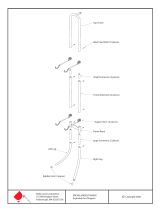
OUTSIDE AIR KIT INSTALLATION

1. Place protective pad or stove pallet on floor.
2. Lay body of stove on its back on protective pad or pallet.
3. Slide pedestal over adapter on bottom of stove
4. Line up holes in sides of pedestal with holes in adapter.
5. Bolt pedestal into place, and tighten securely.
6. Carefully stand stove up and place in desired location.
7. Slip wooden decorative strips onto pedestal edges.
8. Open door of stove and check to insure firebricks and kaowool blanket are in
their proper locations (see pages 25-26).
PEDESTAL MODEL
LEG MODEL
Page 17
1. Place protective pad or stove pallet on floor.
2. Lay body of stove on its back on protective pad or pallet.
3. Bolt cover piece onto mounting brackets, using outer two mounting holes.
4. Slip washers onto bolts, then bolt legs onto mounting brackets.
5. Screw leg assembly onto adapter on bottom of stove using eight 1/4-20 screws.
6. Carefully stand stove up and place in desired location.
7. Use leveling bolts on legs to stabilize and level stove.
8. Open door of stove and check to insure firebricks and kaowool blanket are in
their proper locations (see pages 25-26).
PEDESTAL/LEG KIT INSTALLATION
WARNING: DO NOT OPERATE YOUR QUADRA-FIRE STOVE BEFORE FULLY ASSEMBLING ALL
COMPONENTS. BURNING YOUR STOVE WITHOUT A PEDESTAL OR LEG KIT ATTACHED WILL VOID
YOUR WARRANTY, AND COULD PRESENT A SAFETY HAZARD.
Adapter
Pedestal
FOR INSTALLATION OF
ASH REMOVAL
SYSTEM, SEE PAGE 18.
Mounting bracket
Adapter
Leg
Cover piece

Page 18
1. Remove ash removal system top and
bottom cover plates by loosening nuts
under stove.
2. Discard both plates.
3. Insert ash removal system grate into
opening in firebox floor.
4. Continue with proper installation
according to model you have purchased:
pedestal or leg.
ASH REMOVAL SYSTEM INSTALLATION
1. Place protective pad or stove pallet on floor.
2. Lay body of stove on its back on protective
pad or pallet.
3. Line up holes in ash removal system with
holes in adapter on bottom of stove.
4. Screw ash removal system securely in place.
5. Slide pedestal over ash removal system, and
line up holes in sides of pedestal with holes
in adapter on bottom of stove.
6. Screw pedestal into place, and tighten
securely.
7. Carefully stand stove up and place in desired
location.
8. Slip wooden decorative strips onto pedestal
edges.
9. Open door of stove and check to insure
firebricks and kaowool blanket are in
their proper locations (see pages 25-26).
PEDESTAL MODEL
LEG MODEL
1. Place protective pad or stove pallet on floor.
2. Lay body of stove on its back on protective
pad or pallet.
3. Line up holes in ash removal system with
holes in adapter on bottom of stove.
4. Screw ash removal system in place.
5. Bolt cover pieces onto mounting brackets,
using outer two mounting holes.
6. Slip washers onto bolts, then bolt legs onto
mounting brackets.
7. Screw leg assembly onto adapter on bottom
of stove using eig
ht ¼”-20 screws.
8. Carefully stand stove up and place in
desired location.
9. Use leveling bolts on legs to stabilize and
level stove.
10. Open door of stove and check to insure
firebricks and kaowool blanket are in
their proper locations (see pages 25-26).

ASH REMOVAL SYSTEM OPERATING AND CLEANING
CAUTION: Do not operate stove with ash removal system door open. Store ash in metal container until hot
embers have cooled completely.
1. When stove is cool, open front door and brush most of the ash into the center of the firebox. Remember to
leave ¼” to ½” (6-13mm) of ash on the firebox floor to act as a natural grate, allowing air to flow freely
underneath wood.
2. Clean ash down through the ash removal system grate into the drawer below. If there are large pieces in the
ashes, you can remove the grate before cleaning the ash into the drawer. Be sure to replace the grate before
operating the stove.
3. Release catches on sides of ash removal door.
4. Pull out ash drawer. Close ash removal door. (Closing this door avoids ash blowing into the room in the
event of a downdraft.)
5. Empty ashes into metal container. Store container on non-combustible surface until ashes are cool enough
to dispose.
6. Open ash removal door and replace ash drawer, making sure handle faces forward.
7. Close ash removal door and fasten catches.
Page 19
LEG MODEL
PEDESTAL MODEL

OPERATING INSTRUCTIONS
IMPORTANT - PLEASE READ BEFORE USING STOVE
BURNING PROCESS
In recent years there has been an increasing concern about air quality. Much of the blame for poor air quality has been
placed on the burning of wood for home heating. In order to improve the situation, we at Quadra-Fire have developed
cleaner-burning wood stoves that surpass the requirements for emissions established by our governing agencies. These
wood stoves, like any other appliances, must be properly operated in order to insure that they perform the way they are
designed to perform. Improper operation can turn most any wood stove into a smoldering environmental hazard.
It helps to know a little about the actual process of burning in order to understand what goes on inside a stove. The first
stage of burning we will call the kindling stage. In this stage, the wood is heated to a temperature high enough to evapo-
rate the moisture which is present in all wood. The wood will reach the boiling point of water (212°F) and will not get
any hotter until the water is evaporated. This process takes heat from the coals and tends to cool the stove. Fire requires
three things to burn: fuel, air and heat. So, if heat is robbed from the stove during the drying stage, the new load of wood
has reduced the chances for a good clean burn. For this reason, it is always best to burn dry, seasoned firewood. When
the wood isn’t dry, you must open the air controls and burn the stove at a high burn setting for a longer time to start it
burning. The control on the right side of the stove is called the primary control; it is used mainly during the kindling
stage of burning, or when burning the stove at a high burn setting. It should be closed (pulled outward) for lower burns.
The next stage of burning, the secondary stage, is the period when the wood gives off flammable gases which burn above
the fuel with bright flames. During this stage of burning it is very important that the flames be maintained and not
allowed to go out. This will insure the cleanest possible fire. If you are adjusting your stove for a low burn rate, you
should close down the air to the point where you can still maintain some flame. If the flames tend to go out, the stove is
set too low for your burning conditions. The air control in the center of the stove, beneath the ashcatcher, is the one used
to adjust the stove for lower burn rates. This is called the secondary control. Pulling either control towards you closes it,
pushing it in opens it.
The final stage of burning is the charcoal stage. This occurs when the flammable gases have been mostly burned and
only charcoal remains. This is a naturally clean portion of the burn. The coals burn with hot blue flames. It is very
important to reload your stove while enough lively hot coals remain in order to provide the amount of heat needed to dry
and rekindle the next load of wood. It is best to open the air controls for a short while before reloading. This livens up
the coalbed. Open door slowly so that ash or smoke does not exit stove through opening. You should also break up any
large chunks and distribute the coals so that the new wood is laid on hot coals.
Air quality is important to all of us, and if we choose to use wood to heat our homes we should do so responsibly. To do
this we need to learn to burn our stoves in the cleanest way possible. Doing this will allow us to continue using our wood
stoves for many years to come.
PRIMARY AIR SYSTEM
The primary combustion air enters at the rear of the firebox through the primary air tubes. This air supply is controlled
by the primary control. For maximum burn rates (more heat) push control in, for minimum burn rates (less heat) pull
control out.
SECONDARY AIR SYSTEM
The secondary air enters at the upper front of the firebox, near the top of the glass door. This preheated air supplies the
necessary fresh oxygen to mix with the unburned gases, helping to create secondary, tertiary and quaternary combustions.
This air is regulated by the secondary control. For more secondary air push control in, for less secondary air pull control
out.
Page 20
Primary control
Secondary control
/