Page is loading ...

INSTALLATION & OPERATING
INSTRUCTIONS
CATALOG NO. 6100.62B Effective: 12-18-13 Replaces: 06-21-13 P/N 241519 Rev. 3
WARNING: If the information in these
instructions are not followed exactly, a fire or
explosion may result causing property
damage, personal injury or death.
FOR YOUR SAFETY: Do not store or use
gasoline or other flammable vapors and
liquids or other combustible materials in the
vicinity of this or any other appliance. To do
so may result in an explosion or fire.
WHAT TO DO IF YOU SMELL GAS:
• Do not try to light any appliance.
• Do not touch any electrical switch; do not
use any phone in your building.
• Immediately call your gas supplier from a
neighbor's phone. Follow the gas suppli-
er's instructions.
• If you cannot reach your gas supplier, call
the fire department.
Installation and service must be performed by
a qualified installer, service agency or the gas
supplier
.
This manual should be maintained in legible condition and kept adjacent to the heater or in another safe place for
future reference.
Models 106 & 156
Atmospheric
Above-Ground
Pool & Spa
Heater
(Chauffe-Piscine)
English/French
AVERTISSEMENT: Assurez-vous de bien suivre
les instructions données dans cette notice pour
réduire au minimum le risque d’incendie ou
d’explosion ou pour éviter tout dommage matériel,
toute blessure ou la mort.
Ne pas entreposer ni utiliser d’essence ou ni
d’autres vapeurs ou liquides inflammables à
proximité de cet appareil ou de tout autre appareil.
CE FAIRE SI VOUS SENTEZ UNE ODEUR
DE GAZ:
• Ne pas tenter d’allumer d’appareil.
• Ne touchez á aucun interrupteur; ne pas
vous servir des téléphones se trouvant dans
la bâtiment.
• Appelez immédiatement votre fournisseur
de gaz depuis un voisin. Suivre les instruc-
tions du fournisseur.
• Si vous ne pouvez rejoindere le fournisseur,
appelez le service es incendies.
L’installation et l’entretien doivent être assurés
par un installeur qualifié ou par le fournisseur de
gaz.

2
Rev. 2 reflects the following:
Changes to: Fig. 3 on page 10, Table F on page 13, Fig. 28 on page 29
Additions: None
Deletions: None

WARNINGS 4
Pay Attention to These Terms 4
WATER CHEMISTRY 5
Automatic Chlorinators &
Chemical Feeders 5
SAFETY 6
Water Temperature Safety 6
INTRODUCTION 6
Ratings & Certifications 6
Model Identification 7
Specifications 7
Unpacking 7
INSTALLATION 8
Installation Codes 9
Clearances 9
Base Installation 9
Outdoor Installation 9
Indoor Installation 11
Combustion & Ventilation Air 11
Gas Connections 12
Water Connections 14
Electrical Connections 16
OWNER’S OPERATING
INSTRUCTIONS 17
Control Adjustments—Analog 17
Control Adjustments—Digital 17
Thermostat Operation—Advanced Flame
Technology (AFT) Board 19
Status and Diagnostics 21
Remote Control Installation 22
Wiring Diagrams 24
Post Start-Up Inspection 25
Cold Weather Operation 25
MAINTENANCE 26
SERVICE 26
Water Pressure Switch 26
Flame Roll-Out Safety Switch 27
High Limits 27
Burner Tray Removal 28
Gas Valve Removal 28
Pilot Removal & Cleaning 29
Heat Exchanger Removal 30
Tube Cleaning Procedure 30
De-sooting Procedure 30
Replacement Parts 31
TROUBLESHOOTING 32
Mechanical 32
Electronic Control Logic Flowchart 33
Analog Control Logic Flowchart 34
ILLUSTRATED PARTS LIST 35
CONTENTS
3

DANGER:
Indicates the presence of immediate hazards which will cause severe
personal injury, death or substantial property damage if ignored.
WARNING:
Indicates the presence of hazards or unsafe practices which could cause
severe personal injury, death or substantial property damage if ignored.
CAUTION:
Indicates the presence of hazards or unsafe practices which could cause
minor personal injury or product or property damage if ignored.
NOTE:
Indicates special instructions on installation, operation, or maintenance which
are important but not related to personal injury hazards.
DANGER: Failure to install the drafthood on indoor
installation and properly vent the heater to the
outdoors as outlined in the venting section of this
manual can result in unsafe operation of the heater.
To avoid the risk of fire, explosion, or asphyxiation
from carbon monoxide, never operate this heater
unless it is properly vented and has an adequate air
supply for proper operation. Be sure to inspect the
vent system for proper installation at initial start-up,
and at least annually thereafter. Refer to the venting
section of this manual for more information regarding
vent system inspections.
WARNING: Gasoline, as well as other flammable
materials and liquids (adhesives, solvents, etc.), and
the vapors they produce, are extremely dangerous.
Do not handle, use, or store gasoline or other
flammable or combustible materials in the vicinity of
a heater.
WARNING: Improper installation, adjustment,
alteration, service, or maintenance can cause
property damage, personal injury or loss of life.
Refer to the owner’s operating instructions provided
in this manual. Installation and service must be
performed by a qualified installer, service agency, or
the gas supplier.
WARNING: To minimize the possibility of improper
operation, serious personal injury, fire, or damage to
the heater:
• Always keep the area around the heater free of
combustible materials, gasoline, and other
flammable liquids and vapors.
• Heater should never be covered or have any
blockage to the flow of fresh air to the heater.
WARNING - CALIFORNIA PROPOSITION
65: This product contains chemicals known to the
State of California to cause cancer, birth defects or
other reproductive harm.
WARNINGS - Pay Attention to These Terms
4
WARNING: Both natural gas and propane have an
odorant added to aid in detecting a gas leak. Some
people may not physically be able to smell or
recognize this odorant. If you are unsure or
unfamiliar with the smell of natural gas or propane,
ask your local gas supplier. Other conditions, such
as "odorant fade," which causes the odorant to
diminish in intensity, can also hide, camouflage, or
otherwise make detecting a gas leak by smell more
difficult.
WARNING: Do not install within 3 feet (0.9 m) of a
heat pump or an outdoor condensing unit. Strong air
intake from this type of equipment can disturb the
combustion process and cause damage or personal
injury.
WARNING: UL recognized fuel gas detectors are
recommended in all enclosed propane and natural
gas applications wherein there is a potential for an
explosive mixture of fuel gas to accumulate and their
installation should be in accordance with the
detector manufacturer's recommendations and/or
local laws, rules, regulations, or customs.
WARNING: The heater shall not be located in an
area where water sprinklers, or other devices, may
cause water to spray through the cabinet louvers and
into the heater. This could cause internal rusting or
damage electrical components, and void the warran-
ty.

5
WATER CHEMISTRY
Chemical imbalance can cause severe damage to
your heater and associated equipment. Maintain your
water chemistry according to Table A. If the mineral
content and dissolved solids in the water become too
high, scale forms inside the heat exchanger tubes,
reducing heater efficiency and damaging the heater. If
the pH drops below 7.2, this will cause corrosion of the
heat exchanger and severely damage the heater. Heat
exchanger damage resulting from chemical imbal-
ance is not covered by the warranty.
For your health and the protection of your pool equip-
ment, it is essential that your water be chemically
balanced. The following levels must be used as a
guide for balanced water.
• Occasional chemical shock dosing of the pool or
spa water should not damage the heater providing
the water is balanced.
• Automatic chemical dosing devices and salt chlo-
rinators are usually more efficient in heated water,
unless controlled, they can lead to excessive chlo-
rine level which can damage your heater.
• Further advice should be obtained from your pool
or spa builder, accredited pool shop, or chemical
supplier for the correct levels for your water.
Automatic Chlorinators &
Chemical Feeders
All chemicals must be introduced and completely dilut-
ed into the pool or spa water before being circulated
through the heater. Do not place sanitizing chemi-
cals in the skimmer. High chemical concentrations
will result when the pump is not running (e.g.
overnight).
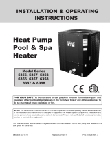
Chlorinators must feed downstream of the heater and
have an anti-siphoning device to prevent chemical
back-up into the heater when the pump is shut off. See
Fig. 1.
NOTE: Corrosive water voids all warranties.
CAUTION: Free chlorine must not exceed 5 ppm
which can damage the heater and is not covered
under warranty.
NOTE: High chemical concentrates from feeders
and chlorinators that are out of adjustment will
cause rapid corrosion to the heat exchanger.
Such damage is not covered under the warranty.
Recommended Level(s) Fiberglass Pools Fiberglass Spas
Other Pool and Spa
Types
Water Temperature 68-88°F (20-31°C) 89-104°F (31-40°C) 68-104°F (20-40°C)
pH 7.3-7.4 7.3-7.4 7.6-7.8
Total Alkalinity (ppm) 120-150 120-150 80-120
Calcium Hardness (ppm) 200-300 150-200 200-400
Salt (ppm) 4500 Maximum 4500 Maximum 4500 Maximum
Free Chlorine (ppm)* 2-3 2-3 2-3
Total Dissolved Solids
(ppm)
3000 Maximum** 3000 Maximum** 3000 Maximum**
*Free Chlorine MUST NOT EXCEED 5 ppm!
** In salt water chlorinated pools, the total TDS can be as high as 6000 ppm.
Table A: Water Chemistry

6
Spa
Return to Spa
Fig. 1: Spa/Chlorinator Setup
SAFETY
This appliance is to be installed and operated by
trained personnel in accordance with this Installation
and Operation Manual. Be sure to read and under-
stand the entire Installation and Operation Manual
before attempting to install or operate this appliance.
Failure to follow the warnings listed at the beginning of
this manual could result in a fire or explosion, causing
property damage, bodily injury, or death.
Should you have any problems understanding the
warnings and instructions in this manual, STOP, and
get help from a qualified installer, service technician,
or the gas supplier.
Water Temperature Safety
Elevated water temperature can be hazardous. The
U.S. Consumer Product Safety Commission has these
guidelines:
1. Spa water temperatures should never exceed
104°F (40°C). A temperature of 100°F (38°C) is
considered safe for a healthy adult. Special cau-
tion is suggested for young children.
2. Drinking of alcoholic beverages before or during
spa or hot tub use may cause drowsiness which
could lead to unconsciousness and subsequently
result in drowning.
3. Pregnant Women Beware! Soaking in water over
102°F (39°C) may cause fetal damage during the
first three months of pregnancy resulting in the
birth of a brain-damaged or deformed child.
Pregnant women should stick to the 100°F (38°C)
maximum rule.
4. Before entering the spa or hot tub, users should
check the water temperature with an accurate
thermometer; spa or hot tub thermostats may err
in regulating water temperatures by as much as
4°F (2.2°C).
5. Persons with a medical history of heart disease,
circulatory problems, diabetes, or blood pressure
problems should obtain a physician's advice
before using spas or hot tubs.
6. Persons taking medications which induce drowsi-
ness, such as tranquilizers, antihistamines,
anticoagulants, or recreational drugs should not
use spas or hot tubs.
INTRODUCTION
Ratings & Certifications
This pool & spa heater (chauffe-piscine) is design-cer-
tified and tested under the latest requirements of ANSI
Z21.56 / CSA 4.7 Standard for Gas-Fired Pool Heaters
(Chauffe-Piscines). The heater can be used either
indoors or outdoors. (Installer å l’intérieur ou à l’ex-
térieur.) If necessary, the top of the heater can be
changed after installation to accommodate indoors or
outdoors.
AVERTISSEMENT: La U.S. Consumer Product
Safety Commission indique que des températures
de l’eau élevées deuvent être dangereuses. Voir la
notice d’installation et de fonctionnement pour le
réglage de lat température. Suivre les instructions
pour une installation appropriée.

7
WARNING: Use of any parts not manufactured
and/or approved by the manufacturer may cause
non-warrantable damage.
Ambient Temperature Rating of
Components
• Analog heater -40°F to +175°F (-40°C to 79.4°C)
• Electronic heater -32°F to +175°F (-35.5°C to
79.4°C)
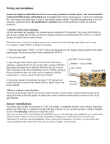
Model Identification
The model identification number and heater serial
number are found on the heater rating plate.
The model identification number will be similar to the
example shown below:
Fig. 2: Location of Heater Rating Plate
Specifications
Unpacking
On receipt of the heater it is suggested that visual
checks are made for external damage to the shipping
carton. If the carton is damaged, make a note to that
effect on the Bill of Lading when signing for the ship-
ment. Remove the heater from the shipping
packaging. Report any damage to the carrier immedi-
ately.
On occasion, items are shipped loose. Be sure that the
correct number of packages are received, as indicated
on the Bill of Lading.
Claims for shortages and damages must be filed with
the carrier by consignee. Authorization to return goods
must be received from the factory prior to shipping.
Goods returned to the factory without an authorized
Returned Goods Receipt number will not be accepted.
All returned goods are subject to a restocking charge.
When ordering parts, specify the model and serial
number of the heater. When ordering under warranty
conditions, specify the date of installation. Records of
the installation must be provided, when requested, to
substantiate a claim.
Debits for defective replacement parts will not be
accepted and will only be replaced in kind per the
manufacturer's standard warranties.
Model
No.
Input*
Gas
Conn.
(NPT)
Water
Conn.
(NPT)
Shipping Weight
Std.
Heater w/
Stackless
Top
Drafthood
Assembly
106
105,000
BTU/hr.
(30.75
KW)
1/2 in.
(1.27
cm)
1-1/2 in.
or 2 in.
(3.8cm
or 5
cm)
85 lbs.
(38.6 kg)
14 lbs.
(6.35 kg)
156
150,000
BTU/hr.
(43.93
KW)
100 lbs.
(45.4 kg)
Table B: Specifications
P - R 106 A - E N - C
Plastic Header
R = Raypak
M = Rheem
D = Ruud
Model No.
Model Rev.
E = Electronic
A = Analog
N = Natural
P = Propane
C = Copper

8
CALIFORNIA PROPOSITION 65 WARNING: This product contains chemicals known to the State of California
to cause cancer, birth defects or other reproductive harm.
IMPORTANT NOTICE
These instructions are intended only for the use by qualified personnel, specifically trained and experi-
enced in the installation of this type of heating equipment and related system components. Installation
and service personnel may be required by some states to be licensed. If your state is such, be sure your con-
tractor bears the appropriate license. Persons not qualified shall not attempt to fix this equipment nor attempt
repairs according to these instructions.
WARNING: Improper installation, adjustment, alteration, service or maintenance may damage the equip-
ment, create a hazard resulting in asphyxiation, explosion or fire, and will void the warranty.
WARNING: This unit contains refractory ceramic fiber (RCF) insulation in the combustion chamber. RCF, as
manufactured, does not contain respirable crystalline silica. However, following sustained exposure to very
high temperatures (>2192F), the RCF can transform into crystalline silica (cristabolite). The International
Agency for Research on Cancer (IARC) has classified the inhalation of crystalline silica (cristabolite) as car-
cinogenic to humans.
When removing the burners or heat exchangers, take precautions to avoid creating airborne dust and avoid
inhaling airborne fibers. When cleaning spills, use wet sweeping or High Efficiency Particulate Air (HEPA)
filtered vacuum to minimize airborne dust. Use feasible engineering controls such as local exhaust ventilation
or dust collecting systems to minimize airborne dust. Wear appropriate personal protective equipment
including gloves, safety glasses with side shields, and appropriate NIOSH certified respiratory protection, to
avoid inhalation of airborne dust and airborne fiber particles.
INSTALLATION

9
Installation Codes
Installations must be in accordance with local, state,
provincial, and national codes, laws, regulations and
ordinances. In the absence of local codes, installations
must be in accordance with the latest editions of the:
• National Fuel Gas Code, ANSI Z223.1/NFPA 54
• National Electrical Code, ANSI/NFPA 70
• For Canada only: CAN/CSA-B149 Installation Code
(B149) and CSA C22.1 C.E.C. Part 1 and Part 2
Clearances
The required minimum clearances from combustible
surfaces are shown in Table C below.
Dégagements minimaux à assurer entre les parois de
l”appareil et les contructions combustibles: 6po
(côtés), 12po (arrière) et 30po (dessus).
When installed according to the listed minimum clear-
ances from combustible construction, the pool heater
can be serviced without removing permanent con-
struction around the heater.
Heater Side
Outdoor
Installations
Indoor
Installations
Top* Unobstructed 30 in. (76.2 cm)
Front 24 in. (61 cm) Alcove
Vent N/A 6 in. (15.2 cm)
Back 12 in. (30.5 cm) 12 in. (30.5 cm)
Right Side 6 in. (15.2 cm) 6 in. (15.2 cm)
Left Side 6 in. (15.2 cm) 6 in. (15.2 cm)
*Clearance from top of vent terminal.
Table C: Required Minimum Clearances from
Combustible Surfaces.
However for ease of servicing, we recommend a
clearance of at least 18" (45.7cm) on the rear. This
will enable the heater to be serviced in its installed
location, that is, without movement or removal of the
heater.
Minimum clearance from drafthood to combustible
construction 6 inches from the vent.
Degagement minimal de 6 po requis entre le coupe-
tirage et une construction combustible. 2 po du conduit
de raccordement.
Clearances less than recommended may require
removal of the heater to service either the heat
exchanger or the burner tray. In either case, the heater
must be installed in a manner that will enable the
heater to be serviced without removing any structure
around the heater.
Base Installation
Heater must be mounted on a level base, such as
cementable slab or cement blocks. Heaters may not
be installed on carpeting.
This heater must b e installed at least 5ft (1.52m) from
the inside wall of a pool unless separated from the
pool by a solid fence, wall or other permanent solid
barrier.
Ce chauffe-piscine doit êntre installè à au moins 5
peds (1.52m) de la paroi interne de la piscine à moins
d’êntre isolé de la piscine par un clôture, un mur ou
autre barrière permanente.
Outdoor Installation
NOTE: The heater should not be located in an area
where possible water leakage will result in damage
to the area adjacent to the heater or to the structure.
When such locations cannot be avoided, it is
recommended that a suitable drain pan, with
adequate drainage, be installed under the heater.
The pan must not restrict combustion air flow.
AVERTISSEMENT: Cet appareil doit être installé
conformément au National Fuel gas Code ANSI
Z223.1, et aux exigences de l’autorité competente.
FLOORING: This heater can be installed on com-
bustible flooring.
WARNING: The heater should not be located in an
area where water sprinklers or other devices may
cause water to spray through the cabinet louvers
and into the heater. This could cause internal rusting
or damage electrical components, and will not be
covered under warranty.
WARNING: Do not install within 3 feet (0.9m) of a
heat pump or an outdoor condensing unit. Strong air
intake from this type of equipment can disturb the
combustion process and cause damage or personal
injury.

10
Fig. 3: Overall Dimensions
Heater with Outdoor Stackless Top
Heaters must not be installed under an overhang of
less than 3 ft (0.9m) from the top of the heater. Three
sides must be open in the area under the overhang.
Roof water drainage must be diverted away from
heaters installed under overhangs with the use of gut-
ters.
Ne pas installer ce chauffe-piscine sous une saillie
mesurant moins de 3 pi de hauteur. La partie sous Ia
saillie doit etre ouverte sur 3 côtes.
• For U.S. installations, the point from where the flue
products exit the heater must be a minimum of 4 ft
(1.2m) below, 4 ft (1.2m) horizontally from, or 1 ft
(0.3m) above any door, window or gravity inlet into
any building. The top surface of the heater shall be at
least 3 ft (0.9m) above any forced air inlet, or intake
ducts located within 10 ft (3m) horizontally. See
Fig. 5.
• For installations in Canada, pool heaters shall not be
installed with the top of the vent assembly within 10 ft
(3m) below, or to either side, of any opening into the
building. Refer to the latest revisions of CAN/CSA-
B149. The heater must be raised 7 in (0.2m) above
the surface which could support snow, ice or debris.
Refer to the latest revisions of CAN1-2.21-M85.
Outdoor Stack
High Wind Conditions
(Outdoor Units Only)
In areas where high winds are frequent, it may be nec-
essary to locate the heater a minimum of 3 ft (0.9m)
from high vertical walls, or install a wind-break so the
heater is not in direct wind current.
In areas of daily high winds, it may be necessary to
replace the outdoor stackless top with a stack adapter
in combination with a wind-resistant/weather-proof
outdoor stack. See Fig. 4.
NOTE: The outdoor stack is optional equipment and
does not come standard with the heater. Use part
number 014718 for the 106 and 014719 for the 156.
NOTE: This heater is design-certified for outdoor
installation when equipped with the approved top(s)
for outdoor use.
OUTDOOR
STACK
Fig. 4: Outdoor Stack
Amp Draw
120 Volt 240 Volt
4 2

11
The outdoor stack serves the same function as the low
profile stackless top and should be installed in accor-
dance with the same clearance requirements. Follow
the installation instructions provided with the Outdoor
Stack Kit for installation.
Indoor Installation
The heater is design-certified for indoor installation
when equipped with the approved drafthood.
Locate heater as close as is practical to a chimney or
gas vent. Heater must always be vented to the out-
side. See Vent Piping section for details. Minimum
allowable space is shown on the rating plate. Follow
the installation instructions provided with the Indoor
Drafthood Kit for installation.
This drafthood must be installed without alteration. see
rating plate.
Ce coupe-tirage doit être installé sans modification.
Voir Ia plaque signalétique.
Combustion & Ventilation Air
(Indoor Units Only)
The heater must have both combustion and ventilation
air. Minimum requirements for net free air supply
openings are one opening that is 12 inches (30.5 cm)
from the ceiling for ventilation, and one opening that is
12 inches (30.5 cm) from the floor for combustion air
as outlined in the latest edition of the National Fuel
Gas Code, ANSI Z223.1 (Canada-CAN/CSA-B149)
and any local codes that may have jurisdiction.
NOTE: For Canada, indoor installation is restricted
to an enclosure that is not occupied and does not
directly communicate with an occupied area. Refer
to the latest edition of CAN/CSA-B149 for specific
requirements.
All Air from inside the building each opening shall•
have a minimum net free area as noted in Table E.
All air from outdoors when air is supplied directly•
from outside the building each opening shall have
a minimum net free area as noted in Table D.
Vent Piping
Vent piping the same size as the drafthood outlet is
recommended, however, when the total vent height is
at least 10 ft (3m) (drafthood relief opening to vent ter-
minal), the vent pipe size may be reduced as specified
in the National Fuel Gas Code, ANSI Z223.1 (Canada
- CAN/CSA-B149). As much as possible, avoid long
horizontal runs of vent pipe and too many elbows.
If installation requires horizontal runs, the vent pipe
must have a minimum of 1/4 in. (2cm per m) per ft rise
and should be supported at not more than five foot
intervals. Plumbers tape, criss-crossed, will serve to
space both horizontal and vertical piping. Gas vents
supported only by the flashing and extending above
the roof more than 5 ft (1.5m) should be securely
guyed or braced to withstand snow and wind loads.
We recommend use of insulated vent pipe spacers
through the roof and walls.
For protection against rain or blockage by snow, the
vent pipe must terminate with a vent cap which com-
plies with local codes or, in the absence of such codes,
the latest edition of the National Fuel Gas Code, ANSI
Z223.1 (Canada - CAN/CSA-B149).
WARNING: Indoor heaters require a drafthood
that must be connected to a vent ppe and properly
vented to the outside. Failure to follow this
procedure can cause fire or fatal carbon monoxide
poisoning.
Model Area
106 105 in² (677 cm²)
156 150 in² (968 cm²)
Model
Unrestricted
opening
Typical screened
or louvered opening
Typical screened
and louvered opening
106 27 in² (174 cm²) 41 in² (265 cm²) 54 in² (348 cm²)
156 38 in² (245 cm²) 57 in² (368 cm²) 76 in² (490 cm²)
CAUTION: Combustion air must not be
contaminated by corrosive chemical fumes which
can damage the heater and void the warranty. Do
not store chlorine, bromine, baquasil or acid in the
same room as the heater.
Table D: Minimum Air Net Area
Table E: Minimum Air Area

12
4 ft (1.2m)
4 ft (1.2m)
1 ft (0.3m)
10 ft (3m)
4 ft (1.2m)
3 ft (0.9m)
Fig. 5: Outdoor Installation Clearances
2’ (0.6m)
MIN
10’ (3m)
OR LESS
2’ (0.6m)
MIN
5’ (1.5m)
MIN
Fig. 6: Vent Piping Requirements
The weight of the vent stack or chimney must not rest
on heater drafthood. Support must be provided in
compliance with applicable codes. The heater top and
drafthood must be readily removable for maintenance
and inspection. Vent pipe should be adequately sup-
ported to maintain proper clearances from combustible
construction.
Type "B" double-wall or equivalent vent pipe is recom-
mended. However single-wall metal vent pipe may be
used as specified in the latest edition of the National
Flue Gas Code ANSI Z223.1 (Canada - CAN/CSA-
B149).
Gas Connections
Gas piping must have a sediment trap ahead of the
heater gas controls, and a manual shut-off valve locat-
ed outside the heater jacket. All gas piping should be
tested after installation in accordance with local codes.
CAUTION: Do not use 5, 10 or 20 gallon (19.38 or
76 Liter) propane tanks, like those used with con-
sumer barbecues, to supply gas to this heater.
CAUTION: The heater and its manual shut-off
valve must be disconnected from the gas supply
during any pressure testing of that system at test
pressures in excess of 1/2 psig (3.5 kPa). The heater
and its gas connections shall be leak tested before
placing the appliance in operation. Use soapy water
for leak test. do not use open flame.
The discharge opening must be a minimum of 2 ft
(0.6m) vertically from the roof surface and at least 2 ft
(0.6m) higher than any part of the building within 10 ft.
(3m) vent stack shall be at least 5 ft (1.5m) in vertical
height above the drafthood outlet. The vent cap loca-
tion shall have a minimum clearance of 4 ft (1.2m)
horizontally from, and in no case below, unless a 4 ft
(1.2m) horizontal distance is maintained, from electric
meters, gas meters, regulators and relief equipment.

13
Fig. 7: Gas Line Sediment Trap
NOTE: Do not use Teflon tape on gas line pipe
thread. A flexible pipe sealant suitable for LP gases
is recommended.
Gas Pressure Regulator
The gas pressure regulator is preset at 4.0 in W.C.
(1.0kPa) for natural gas and 10.0 in W.C. (2.5kPa) for
propane gas.
If adjustment is needed, remove plug and turn adjust-
ment screw clockwise to increase pressure or
counter-clockwise to decrease pressure.
Gas Pressure* Natural Gas Propane Gas
Max. Inlet
(static)
10.5 in. WC
(2.6 kPa)
13 in. WC
(3.2 kPa)
Min. Inlet
(dynamic)
5 in. WC
(1.2 kPa)
11 in. WC
(2.7 kPa)
Manifold Gas
(dynamic)
4 in. WC
(1.0 kPa)
10 in. WC
(2.5 kPa)
*Static means without heater operating, dynamic refers to heater
operating.
Table F: Gas Pressure
Gas Pressure Adjustment Locations
Fig. 8: Honeywell Gas Valve
Electronic Ignition Gas Valves
Fig. 9: Location of Gas Pressure Adjustment

14
Pipe Sizing for Gas Connections
Water Connections
The heater requires water flow and positive pressure
to fire and operate properly. It must therefore be
installed downstream of the discharge side of the filter
pump. A typical installation is plumbed as follows:
1. The inlet side of the filter is plumbed directly to the
discharge side of the filter pump;
2. The outlet side of the filter is then plumbed to the
inlet of the heater; and
3. The outlet of the heater is plumbed to the return
line to the pool or spa. The pump, filter and heater
are thus plumbed in series.
Plumbing from the heater back to the pool or spa must
not have any valves or restriction that could prevent
flow when the pump is operating.
Heater must be located so that any water leaks will not
damage the structure of adjacent area. PVC pipe may
be glued directly into supplied CPVC header unions.
Flow Rates
Table G: Maximum Equivalent Pipe Length
Polymer Headers
Before attaching the supplied 2-inch (5 cm) CPVC
unions to the In/Out header, make sure the O-rings are
properly seated in the grooves. Use AquaLube or
equivalent non-petroleum-based lubricant on the O-
ring. Hand tighten the unions. Glue PVC or CPVC
piping directly to the unions.
Model No. Minimum Maximum
106/156 20 GPM (75 L) 70 GPM (265 L)
*When flow rates exceed maximum 70 GPM, an external auxiliary
bypass valve is required. See External Auxiliary Bypass Valve sec-
tion for details.
Table H: Water Flow Rates
In/Out Header
O-Ring
Tail Piece
Nut
2” Pipe
(5cm)
Drain Plug
In/Out Header
Hose Connector
Hose
Fig. 10: In/Out Header for 2" Installation
Fig. 11: Optional In/Out Header for 1-1/2" (3.8 cm)
or 1-1/4" (3.2 cm) Hose Connection
NAT LPG NAT LPG NAT LPG
105,000 BTU/hr 26 ft 65 ft 99 ft 252 ft 350 ft 892 ft
(30.8 kW) (8 m) (20 m) (30 m) (77 m) (107 m) (272 m)
150,000 BTU/hr 13 ft 34 ft 51 ft 130 ft 180 ft 459 ft
(43.9 kW) (4 m) (10 m) (16 m) (40 m) (55 m) (140 m)
* Natural Gas 1000 BTU/FT
3
0.60 Specific Gravity @ 0.5 in WC Pressure Drop
(Gaz Naturel 3154.5 W/m
3
0.60 Densité @ 0.124 kPa Pressure Drop)
* Propane Gas 2500 BTU/FT
3
1.53 Specific Gravity @ 0.5 in WC Pressure Drop
(Le Gaz Propane 7886.3 W/m
3
1.53 Densité @ 0.124 kPa Pressure Drop)
1/2 in. (1.27cm)
3/4 in. (1.91cm)
1 in. (2.54cm)
Model
Tubing
Input
Cu
Cu
106
156

15
If there is any possibility of back-siphoning when the
pump stops, it is recommended that a check valve (or
valves) also be installed in the system.
Internal Automatic Bypass Valve
A built-in automatic bypass valve is provided in the
In/Out header. The internal bypass valve automatical-
ly responds to changes in water pressure in the piping
system. The proper amount of water flow is maintained
through the heater under varying pressures dictated
by the conditions of the pump and filter.
External Auxiliary Bypass Valve
An auxiliary bypass valve must be used when flow
rates exceed 70 GPM (265 LPM). Usually a high-per-
formance pump size larger than one horsepower will
exceed this flow rate. This valve is required to comple-
ment the function of the automatic bypass valve,
particularly when starting the heater in winter or early
spring when the spa or pool temperature is below 50°F
(10°C). It also serves to eliminate needless pressure
drop through the heater and accompanying reduction
in the flow rate to the spa jets, etc.
Bypass Disc
Spring
Bypass Body
Fig. 12: Internal Automatic Bypass Valve
From Heater
To Heater
To Pool/Spa
Bypass Valve
From
Pool/Spa
Full Port
Ball Valve
or Globe
Valve
Fig. 13: Auxiliary Bypass Valve
NOTE: Do not use a gate valve as an auxiliary
bypass valve.
Auxiliary Bypass Valve Adjustment
To set bypass: With clean filter, adjustment is made by
feeling the inlet and outlet pipes at the heater. Outlet
pipes should be slightly warmer than inlet and comfort-
able to the touch. If pipe is hot, close bypass; if cold,
open bypass.
Pressure Relief Valve Installation
To conform to local building codes, it may be neces-
sary to install a pressure relief valve. A 3/4" (1.9 cm)
pressure relief valve, having a capacity equal to or
greater than the BTUH input of the heater to be
installed, is recommended for this heater. The maxi-
mum pressure relief valve setting is 125 psi (862 kPa).
This relief valve needs to be installed on the outlet pipe
from the header as noted in Fig. 14 below.
If required, this needs to be installed in a field-supplied
fitting external to the heater. The valve shall be
installed in a vertical position. Do not over-tighten.
Install the pressure relief valve hand tight plus 1/2 turn.
The valve lever should be tripped at least once a year
to ensure that waterways are clear. If the relief valve
does not function properly, replace it immediately.
PIPE ONTO DISCHARGE SIDE OF PIPING
Fig. 14: Pressure Relief Valve Installed
WARNING: To avoid water damage or scalding due
to relief valve operation, drain pipe must be
connected to valve outlet and run to a safe place of
discharge. Drain pipe must be the same size as the
valve discharge connection throughout its entire
length and must pitch downward from the valve. No
shut-off valve shall be installed between the relief
valve and the drain line.

16
Installation Instructions—240 Volt
1. Disconnect and remove 120 volt power cord.
2. Install wire nut on white transformer wire.
3. Wire nut 240 volt supply lines to the red and black
wire on the transformer.
4. Wire nut green supply ground line to green trans-
former wire
CAUTION: This heater has provisions to be
connected to an alternate supply source. To reduce
the risk of electric shock, disconnect all connections
before servicing.
240V HOOK-UP
HEATER
L1
L2
RED RED
BLACK
HOT
HOT
BLACK
GREENGREEN
WHITE
SUPPLY
SIDE
Fig. 16: 240V Hook-Up
Heat Exchanger Pressure Drop
Table
Electrical Connections
Be sure that electrical service to the heater has prop-
er overload fuse or circuit breaker protection, wire size
and connections which comply with all applicable
codes.
If any of the original wire as supplied with the appli-
ance must be replaced, it must be replaced with type
302°F (150°C) wire or its equivalent.
Si un des fils original fourni avec l'appareil doit être
remplacé, utilisez un fil 302°F (150°C), ou l'équivalent.
The heater comes standard with a 120 VAC 3-prong
power cord. For 240 VAC applications, see figure 18.
Power source must be a wired ground, with ground
fault circuit interruption circuitry.
Flow (GPM) Pressure Drop (ft of Head)
20 7.6
30 8.2
40 8.7
50 9.3
60 9.8
70 10.4
Table I: Pressure Drop
The heater must be electrically grounded and bonded
in accordance with local codes, or, in the absence of
local codes, with the latest edition of the National
Electrical Code, ANSI/NFPA 70. (Canada - Canadian
Electrical Code, CSA C22.1, Part 1 and Part 2.)
Fig. 15: Electronic Heater Power
NOTE: Input power to the heater (120 VAC) can be
supplied from the load (pump) side of time clock or
directly from the GFCI power source. It is preferred
to make connection to the load/pump side of the time
clock.
WARNING: Risk of electrical shock. More than
one disconnect switch may be required to de-
energize the equipment before servicing.
CAUTION: Label all wires prior to disconnection
when servicing controls. wiring errors can cause
improper and dangerous operation.
ATTENTION. Au moment de l'entretien des
commandes, étiquetez tous les fils avant de les
débrancher. Des erreurs de câblage peuvent
entraîner un fonctionnement inadéquat et
dangereux.

Control Adjustments—Digital
The pool heater (chauffe-piscine) touchpad, located
on the upper front panel of the heater, allows the user
to select either POOL or SPA operation, and to adjust
the setpoint temperature. The LCD display window
indicates the mode (OFF, SPA, POOL) and the actual
water temperature. A manual power switch provided
below the touchpad turns the control power ON or
OFF.
OWNER’S OPERATING
INSTRUCTIONS
Control Adjustments—Analog
The pool or spa water temperature is controlled by the
thermostat on the upper front panel of the heater. The
control center contains an On/Off toggle switch and a
thermostat. The switch functions as a means for turn-
ing the heater On or Off.
The thermostat is fitted with a means of limiting the
upper temperature limit below the maximum level. The
knob stop adjustment ring shown in Fig. 17 is
adjustable by loosening the set screw, rotating the
knobstop ring to the desired location, and retightening
the set screw.
17
HOT
COOL
Knobstop Ring
Knobstop Set Screw
Fig. 17: Water Temperature Thermostat
NOTE: Maximum temperature is 104°F (40°C).
Fig. 18: Digital Control Adjustment
MENU/SET Button
The MENU/SET button is used to select either POOL
or SPA operation. It also allows the user to turn the
heater off electronically. The LCD remains energized
and displays OFF, while also continuing to show the
actual water temperature.
Temp Buttons
If the heater is in POOL or SPA mode, the desired
water temperature (SETPOINT) will also be displayed
and may be adjusted using the UP or DOWN buttons.
Operation
In the POOL or SPA modes, the actual water temper-
ature is displayed along with the desired water
temperature (SETPOINT). When the water tempera-
ture is above the setpoint, “Water Temp” will alternate
with “No Demand.” When the water temperature is
below the setpoint and the heater is firing, “Water
Temp” will alternate with “Heating.”
To adjust the setpoint temperature, make sure the con-
trol is in the appropriate mode (POOL or SPA) and
push the UP or DOWN buttons.
ALTERNATING DISPLAYS DURING HEATING

18

19
Service Menu and Fault History
To access the Service Menu and fault history, press
the MENU/SET and UP buttons simultaneously for 3 to
5 seconds. The heater will continue to operate nor-
mally while in the Service Menu. The first screen
displayed is the Flame Strength indicator, which indi-
cates the pilot flame current using a bar graph and
numerical display. A signal of less than 4 indicates a
weak flame signal and may require service. Refer to
Section 5 – Troubleshooting for possible causes and
corrections.
Program
button
FLAME STRENGTH INDICATOR
SUPPLY VOLTAGE INDICATOR
RUN TIME INDICATOR
Press the DOWN button. The Supply Voltage screen
indicates the voltage supplied to the control board.
Normal readings range from 24 to 29 volts.
Press the DOWN button. The Run Time indicates the
total hours of operation for the pool heater, as meas-
ured by the amount of time that the main gas valve has
been powered. The Cycle count indicates the number
of on/off cycles of the heater, as measured by the
number of times the pilot valve has been powered.
FAULT HISTORY
Press the DOWN button. The Fault History can dis-
play up to ten faults in memory. The order of the faults
begins with “Fault Last,” which is the most recent fault,
and proceeds through ten most recent messages in
chronological order. The second line of the display
shows the fault message. If there are no faults in the
history buffer, the second line reads “All Faults Clear.”
Thermostat Operation—
Advanced Flame Technology (AFT) Board

20
Resets board to factory default
settings.
Resets faults in the History File.
Change from Fahrenheit to
Celsius.
SPA setpoint maximum adjustment.
POOL setpoint maximum
adjustment.
Set Factory Defaults
Refer to step one above to access the program
screen. Set Factory Defaults should appear on the
screen. If it does not, press the MENU/SET button until
Set Factory Defaults appears on the digital display.
Press and hold both UP and DOWN buttons for 5-7
seconds until Defaults Set appears. This operation
resets the operating program to its factory default val-
ues. Both the POOL and SPA setpoints will revert to
65°F (18.5°C) and both POOL and SPA maximum
temperature settings will be 104°F (40.0°C). The
Control Lockout PIN will be cleared and the control will
resume normal operation.
Clear Faults
Refer to step one above to access the program
screen. Press the MENU/SET button until Clear
Faults appears on the digital display. Press and hold
both UP and DOWN buttons for 5-7 seconds until
Faults Cleared appears. This operation resets the
Fault History file to “0” and clears all the stored faults.
Program Button
1) Remove the four screws holding the control cover,
and swing the panel down so the back side of the
board is visible (see page 31). Locate the Program
Mode button (marked as SW1) as shown on page
33. Press and hold the button (5-7 seconds) until
Set Factory Defaults appears on the display.
Release the program button.
2) Press the MENU/SET button sequentially until the
desired program event is reached. There are 5 dif-
ferent events that can be programmed. They
appear in the sequence listed below:
Fahrenheit or Celsius
Refer to step one above to access the program
screen. Press the MENU/SET button until Fahrenheit
or Celsius appears on the digital display. The digital
display is capable of displaying Celsius as well as
Fahrenheit temperatures. The UP or DOWN buttons
will select Fahrenheit or Celsius on the temperature
display. Choose the desired temperature scale.
Spa Max Temp – Spa Set Point Maximum
Adjustment
Refer to step one above to access the program
screen. Press the MENU/SET button until Spa Max
Temp appears on the digital display. Using the UP and
DOWN buttons will change the Maximum Temperature
Setting to your desired value. The control can be set
for a maximum of 107°F (41.7°C).
Pool Max Temp – Pool Set Point Maximum
Adjustment
Refer to step one above access into the program
screen. Press the MENU/SET button until Pool Max
Temp appears on the digital display. Using the UP and
DOWN buttons will change the Maximum Temperature
Setting to your desired value. The control can be set
for a maximum of 107°F (41.7°C).
Control Lockout
The heater is equipped with a Control Lockout feature
to prevent unauthorized tampering or adjustment of
the control settings. To lock out the controls, press the
DOWN button and MENU/SET button for 5 seconds.
Choose a three digit PIN, using the UP and DOWN
buttons to select the digits and the MENU/SET button
to lock in selections. Confirm your selection and
record your PIN.
To unlock the controls, press any button to bring up the
Enter PIN menu. Enter the PIN that was used to lock
the control. Note that power cycling will not clear the
lockout. Successfully unlocking the control will display
“Lockout Cleared.” Failure to enter the correct PIN will
display “Invalid PIN.”
In the event that the user-selected PIN is lost or does
not clear the Control Lockout, use the Program Button
to Set Factory Defaults. This will clear the PIN and
allow normal operation and selection of a new PIN if
desired. See the Program Button directions on this
page for details.
NOTE: Both the POOL and SPA setpoints will revert
back to 65°F (18.5°C) and the POOL and SPA maxi-
mum temperature settings will be 104°F (40.0°C).
These setpoints will need to be readjusted to desired
settings.
/