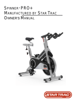
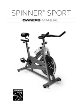
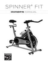
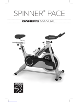
Star Trac Spinner V 7060 Installation guide

Type
Installation guide
620-8006 Rev A
STAR TRAC
14410 Myford Road
Irvine, CA 926060 USA
COVER PAGE FOR DOCUMENT CONTROL PURPOSES ONLY, NOT TO BE PRINTED
Document:
Document Title: MANUAL, SP INSTALLATION, NXT
Document Number:620-8006 Rev: 001
Page Number: 1 of 16
Material:
n/a
Notes:
n/a
Approvals:
Originator
Print:
Deo Magakat
Sign: Date: 04/12/11
Approved By:
Sign: Date:
Document Revision History:
REV EFFECTIVE DATE
BY
DESCRIPTION ECO NO.
01
DMM
DRAFT
A
14 June 2011
DMM
RELEASE 13510
THE INFORMATION CONTAINED HEREIN IS PROPRIETARY AND CONFIDENTIAL TO UNISEN INC/STAR TRAC.
AND SHALL NOT BE USED OR DISCLOSED, IN WHOLE OR IN PART, WITHOUT FIRST OBTAINING THE WRIT-
TEN PERMISSION OF UNISEN, INC.
Print:
2
620-8006 Rev A
STAR TRAC
14410 Myford Road
Irvine, CA 926060 USA
SPINNER ASSEMBLY AND
INSTALLATION MANUAL
3
620-8006 Rev A
GENERAL
Before using this product, it is essential to read ALL installation Instructions and this
ENTIRE operations manual; the manual describes equipment setup and instructs
members on how to use it correctly and safely.
1. Open-End Wrench (Included)
2. Multi-purpose Wrench (Included)
3. 14mm Socket Wrench (Not Included)
4. 18mm Socket Wrench (Not Included)
5. 18mmHex Wrench (Not Included)
6. 21mm Open-end Wrench (Not Included)
7. Torque Wrench (Not Included)
8. Loctite 242 (Not Included)
9. Loctite 262 (Not Included)
TOOLS REQUIRED
If you are a Factory Certified Installer you must:
Adhere to all torque and assembly specifications.
Use a CALIBRATED TORQUE WRENCH with the necessary hex key sockets
NOT USE a powered drill, powered driver or powered impact tool for any part of the assembly.
Complete the assembly checklist on each Star Trac product.
Complete the final programming, functional and cosmetic checklists for each Star Trac product.
FACTORY CERTIFIED INSTALLER
Copyright 2011. Star Trac by Core Industries, Inc., Star Trac Fitness, Star Trac®, and the Star Trac Logo are registered trademarks of Core Ind, Inc.
All rights reserved, including those to reproduce this book or parts thereof in any form without first obtaining written permission from Star Trac.
Spin
®
, Spinner
®
, Spinning
®
and the Spinning logo are registered trademarks of Mad Dogg Athletics, Inc.
Smart Release™ is a registered trademark of Nautilus, Inc.
SPD is a registered trademark of Shimano American Corporation.
Every effort has been made to keep this information current; however, periodically, changes are made to the information herein, and these changes
will be incorporated into new editions of this publication. All product names and logos are trademarks of their respective owners.
4
620-8006 Rev A
Step 3.
Fold back all flaps at the top and at the bottom of
the box.
Step 4.
Slide-up the outer carton.
Step 2.
Open the carton first at the top and bottom. Use
scissors or a knife to cut the tape.
Caution: Be careful not to injure yourself; always
cut away from your body.
Step 1.
Arrange the assembly area so that the area is free
from objects that could potentially damage the
parts.
When positioning the box verify that the
HEAVY END logo is at the bottom as indicated by
the black oval in the picture.
UNPACKING INSTRUCTIONS
5
620-8006 Rev A
Step 8.
Position the main frame assembly upright and
remove plastic protector.
Step 6.
Remove the foam inserts from the shipment by
first taking out foam insert (1), then foam inserts
(2), and then last foam insert (3).
Step 5.
Arrange the unpacking area so that the area is
free from objects that could potentially damage
unpacked components.
Step 7.
Remove components from foam inserts.
1
2 3
6
620-8006 Rev A
Step 9.
Place the main frame assembly on a flat surface
that is free from objects that could potentially
damage the unit.
Step 12.
Verify that the Spare Kit contains:
1. Pedal straps (2)
2. Spare brake pad (1)
Note: If the shipment is incomplete please con-
tact the Service Department at (800) 503-1221.
Step 10.
Verify that all shipment components are included:
1. Hardware, Pop-pin, and Pedals (set of two)
2. Handlebar w Grip and Water Bottle Holders (1)
3. Handlebar Post (1)
4. Seat Post (1)
5. Rear Leg Assembly (1)
6. Seat Slider Assembly w/Saddle (1)
7.
Front Leg Assembly w/Transport Wheels (1)
1
2
1
3
4
5
6
7
2
2
1
3 4
7
5
6
Step 11.
Verify the Hardware Kit contents:
1. M10 Flat Washer (4)
2. M10 Split Lock Washer (4)
3. M10X1.5, 25mm Hex Head Screw (4)
4. M8X1.25, 12mm Flange Hex Head Screw (2)
5. Open-End Wrench (1)
6. Multi-purpose Wrench (1)
7. Hex Wrenches (3)
7
620-8006 Rev A
Step 14.
Locate (2) M10 Hex Head screw. Pre-install an M10
Split Lock Washer and an M10 Flat Washer onto each
Hex head screw.
Note: Pay attention to the order of assembly of the
Split Lock Washer and Flat Washer.
Step 13.
Place the rear leg assembly in the mating position
under the frame.
Note: Make sure the thread posts in the frame
and the holes in the rear leg assembly are in
alignment.
ASSEMBLY INSTRUCTIONS
Step 15.
Secure the rear feet to the frame using (2) M10
Hex Head Screws with (2) M10 Split Lock Wash-
ers, and (2) M10 Flat Washer.
Torque screws to 35-40 lb-ft (47-54 Nm).
Note: Start threading screws by hand, then
tighten using an 18mm open-end or socket
wrench.
Step 16.
Secure the front feet to the frame using (2) M10 Hex
Head Screws with (2) M10 Split Lock Washers, and
(2) M10 Flat Washer.
Torque screws to 35-40 lb-ft (47-54 Nm). Verify
that the front and rear feet are parallel to each
other.
Note: Start threading screws by hand, then tighten
using an 18mm open-end or socket end wrench.
8
620-8006 Rev A
Step 20.
Locate the Pop-pin shown above.
Step 17.
Slide the Handlebar w/ Grip and Water Bottle
Holder onto the Handlebar Post.
Note: You may have to pull up on the Lock Knob
to help align the Slider Clamp with the guide rail.
Step 18.
Using a 2.5mm Hex Key, tighten the Button Head
Screw all the way down. This screw limits the
travel of the Handlebar and prevents the Handle-
bar from sliding off the Handlebar post acciden-
tally.
Note: Verify that no gap exists between the head
of the screw and the Handlebar slide rail.
Step 19.
Loosen the Pop-pin and pull it out away from the
Frame Handlebar Post.
Install and slide the Handlebar assembly into the
Frame Handlebar Post.
9
620-8006 Rev A
Step 23.
Align the slider clamp with the guide rail by turning
the Seat Slider Lock Knob.
Pull down on the locking pin and slide the seat rail
onto the seat post assembly.
Step 22.
With the Pop-pin loose pull and hold it away from
the frame seat post.
Install Seat Post into the Frame Seat Post.
2
1
Step 24.
Release the locking pin when the arrow points to a
value between 0 and 7.
Step 21.
Install the Pop-pin into the Frame Seat Post using
a 21mm Open-end Wrench.
10
620-8006 Rev A
Step 25.
Locate the set of left and right pedals and follow
the orientation as shown in the picture above dur-
ing installation.
Step 28.
Secure the pedal tightly by using a 14mm Socket
wrench. Do not use an open end wrench to
tighten the pedal screws.
Torque screw to between 35-40 lbs-ft (47-54
Nm). Cover screw with Plastic End Cap.
Note: To prevent the pedal/crank arm from rotat-
ing, lock down the flywheel by turning the Brake
Resistance knob clockwise all the way down.
Step 26.
Locate one (1) M8x1.25 Flanged Hex Head
Screw, and (1) Plastic End Cap.
Note: Check to make sure the screw has a blue
or red Loctite patch on the threads.
L R
Step 27.
Using a rubber mallet, firmly tap the left pedal
shaft into the left crank arm to seat and engage
the tapered shaft securely.
Start threading in the M8X1.25 Flanged Hex
Head screw by hand into the end of the pedal
shaft.
Note: Check Crank Arm tapered hole and verify
that it is free of burrs or other debris. Verify that
the pedal tapered shaft is burr-free and clean.
11
620-8006 Rev A
Step 30.
Verify that the bike is placed on a flat surface.
Next, make sure that all four feet are screwed up
all the way into the stabilizer bars.
Step 29.
Repeat pedal installation for the right side.
Verify that the pedal is properly installed by
checking that the gap as shown is between 5-
6mm (.20” to .24”) max.
Step 31.
Adequately stabilize the bike by adjusting the lev-
eling feet.
Note: Leveling the bike can usually be accom-
plished by adjusting one foot only.
12
620-8006 Rev A
FUNCTIONAL TEST
Step 32.
Verify that the Seat Slider travels all the way back
until the indicator points at position 7 (or 9 de-
pending on your model).
Step 33.
Verify that the Seat Slider travels all the way for-
ward until the indicator points at position 0
.
Secure the Seat Slider Post by turning the Seat
Slider Lock Knob clockwise.
Note: At Seat Slider position “0” the guide rail
rear end caps should be aligned.
Step 34.
Adjust the Seat Height.
Loosen and pull out the Pop-Pin, then lift the Seat Post
up to higher levels while holding the Pop Pin out.
Check for Pop-Pin engagement with the mating holes
on the Seat Post each time you move up the Seat Post
to a higher position.
Tighten pop pin.
13
620-8006 Rev A
Step 36.
Check Fore-and-Aft Adjustment of the Handlebar
by sliding the handlebar forward and backward.
Position the Handlebar to its rearmost stop and
lock in position by turning Lock Knob clockwise.
Step 35.
Adjust the handlebar. Loosen and pull out the
Pop-Pin, then lift the Handlebar Post up to higher
levels while holding the Pop Pin out.
Check for Pop-Pin engagement with the mating
holes on the Handlebar Post each time you move
up the Handlebar to a higher position.
Tighten pop pin.
3
1
2
Step 37.
Mount the bike and check for steadiness.
14
620-8006 Rev A
Step 39.
Push down the Resistance Knob sharply
(emergency braking) to make sure the Flywheel
rotation stop abruptly.
Step 38.
Test bike operation:
1. Mount the bike.
2. Turn Resistance Knob in the counterclockwise
direction to reduce brake resistance as
indicated by the “-” symbol.
3. Start pedaling when resistance is low.
4. Verify that pedaling is smooth and that there
is no excessive noise or wobble.
5. Increase the resistance by turning Knob in
clockwise direction (“+” symbol) and verify
that it changes accordingly. Confirm there is
no excessive noise or wobble.
6. Decrease the resistance and verify that it
changes accordingly.
15
620-8006 Rev A
ATTENTION
Star Trac recommends that Spinner bikes be spaced a minimum of 20.0 inches (0.5 m) apart to allow safe and
easy ingress and egress.
As with any exercise equipment, the area where Spinner bikes are located must be free of obstructions and fixtures
with sharp edges to prevent injury in the event that a user trips or loses balance and falls.
Use the checklist below to ensure the proper installation of the bike
1. Rear and front leg assemblies are properly installed and secured.
2. Handlebar post height adjustment moves freely and can be locked in all levels.
3. Handlebar fore-and-aft slider adjusts freely and can be locked in all levels.
4. Seat Post height adjustment moves freely and can be locked in all levels.
5. All screws are tightened and torqued down to the specified torque value.
6. Pop pins are secured and freely engage and disengage mating holes.
7. Seat slider is properly installed and slides freely along the entire range of motion.
8. Seat slider can be locked in all levels.
9. Right and left pedals are properly installed.
10. Resistance knob operates properly and, when applied, flywheel stops
abruptly.
For technical assistance call Star Trac Customer Service: 1 800 503 1221
16
620-8006 Rev A
STAR TRAC
14410 Myford Road
Irvine, California 92606
Telephone: (800) 228-6635, (714) 669-1660
Fax: (714) 508-3303
http://www.startrac.com
  • Page 1 1
  • Page 2 2
  • Page 3 3
  • Page 4 4
  • Page 5 5
  • Page 6 6
  • Page 7 7
  • Page 8 8
  • Page 9 9
  • Page 10 10
  • Page 11 11
  • Page 12 12
  • Page 13 13
  • Page 14 14
  • Page 15 15
  • Page 16 16

Star Trac Spinner V 7060 Installation guide

Type
Installation guide

Ask a question and I''ll find the answer in the document

Finding information in a document is now easier with AI