Page is loading ...

User’s and
Installation Manual
DryStar Monitor
Dry Vacuum System
Part Nos: LT3M and LT5M
RECOMMEND DAILY
USE OF MONARCH
CLEANSTREAM

Air Techniques, Inc.
Page
2
Section Page
Congratulations ......................................................3
Intended Use ........................................................3
Safety Summary ......................................................3
Purpose of this Manual.................................................4
Sizing Guide ........................................................4
Specifications........................................................4
Product Description ...................................................5
Installation Information.................................................8
Installation..........................................................14
Electrical Connections .................................................16
Operating Information .................................................18
Touch Screen Controls .................................................20
Vision Monitor, Remote Monitoring Solution ..................................26
Maintenance ........................................................27
Accessories/Options...................................................29
Troubleshooting ......................................................30
Warranty ...........................................................31
On-Line Warranty Registration............................................31
TABLE OF CONTENTS
Figure Title Page
1 MOJAVE LT Key Parts Identification ...............................5
2 MOJAVE LT, LT3M and LT5M, Functional Connection Points .............6
3 MOJAVE LT, LT3M and LT5M, Vacuum Pump Dimension ...............7
4 MOJAVE LT System Floor Plan ..................................9
5 MOJAVE LT Plumbing Connection ..............................10
6 MOJAVE LT Detail Plumbing Connection..........................11
7 MOJAVE LT Power Connection .................................12
8 Remote Switch Connection to Main Board ........................12
9 3-Wire and 4-Wire Remote Switch Connection .....................13
10 MOJAVE LT Front Panel Controls and Indicators ....................14
11 CleanStream Dispenser Cap Adapter Locations ....................25
LIST OF ILLUSTRATIONS

Page
3Air Techniques, Inc.
CONGRATULATIONS
SAFETY SUMMARY
Use of the MOJAVE LT not in conformance with the instructions specified in this manual
may result in permanent failure of the unit.
WARNING: To prevent fire or electrical shock, do not expose this equipment
to rain or moisture.
All user serviceable items are described in the maintenance section.
Manufacturing date code on serial number label is in the format Month YYYY.
ATTENTION USERS:
Markings. The following terms or symbols are used on the equipment or in this manual to
denote information of special importance:
Alerts users to important Operating
and Maintenance instructions. Read
carefully to avoid any problems.
Warns users that uninsulated voltage
within the unit may be of sufficient
magnitude to cause electric shock.
Indicates the ON and OFF position for
the Equipment power switch.
I ON
O OFF
Indicates protective Earth Ground for the
Equipment power switch.
Warns users of hot surfaces. There is a danger
of burns. Work near these surfaces only after
they have cooled down.
Indicates date of manufacture
Identifies the name of the
manufacturer.
MEDICAL ELECTRICAL EQUIPMENT
WITH RESPECT TO ELECTRICAL SHOCK, FIRE, MECHANICAL
AND OTHER SPECIFIED HAZARDS ONLY
IN ACCORDANCE WITH UL 60601-1, CAN/CSA C22.2 No. 601.1
66CA
C
L
A
S
S
I
F
I
E
D
Air Techniques, Inc.
1295 Walt Whitman Road
Melville, New York, USA 11747- 3062
INTENDED USE
The MOJAVE LT creates vacuum that will be used in a dental facility.
Congratulations on the purchase of the MOJAVE LT DryStar Monitor Dry Vacuum System, which
is hereafter referred to as MOJAVE LT in this manual. MOJAVE LT is available in single pump
configurations. Single pump systems include the LT3M and LT5M. Each system provides state of the
art vacuum technology designed for reliable operation in the modern dental facility. The system
uses a 100% water-less Vacuum Pump to produce the high-volume air flow required for multiple
simultaneous users while the Air/Water Separator ensures that no liquids enter the pump.
MOJAVE LT incorporates an efficient energy management system. This is accomplished by
adding a Variable Frequency Drive (VFD) to the Vacuum Pump. This system automatically
adjusts the frequency of the pump to maintain the required vacuum level depending on the
needs of your dental facility. With this balanced system, each user always has the flow rate
necessary to do the job while conserving electricity and prolonging the life of your pump.

Air Techniques, Inc.
Page
4
To ensure optimum operation, the demands should not exceed the number of vacuum users shown
below. The chart lists the number of simultaneous High Volume Evacuators (HVEs) and Saliva
Ejectors (SEs) that can be used by the MOJAVE LT system.
SIZING GUIDE
SPECIFICATIONS
Pump Electrical
Specifications LT3M LT5M
Voltage (Volts AC ± 10%)220 220
Full Load Current (Amps AC) 15 15
Input Frequency (Hz) 60 60
Preset Vacuum Level (InHg) 8 8
Horsepower 1.0 kW or 1.4 HP 1.3 kW or 1.7 HP
System Environmental Conditions (All Systems)
Operating Temperature 50 to 105°F or 10 to 40°C
Storage and Transport Temperature 32 to 158°F or 0 to 70°C
Operating Relative Humidity 80%, no condensation
Storage and Transport Relative Humidity 90%, no condensation
UL60601-1 CLASSIFICATION
Protection against electrical shock (5.1, 5.2) Class I, Transportable, Continuous Operation.
No applied parts. Protection against ingress of liquids-Ordinary Equipment not suitable for
use in the presence of flammable anaesthetic mixture with air or with oxygen or nitrous oxide.
All MOJAVE LT vacuum pumps comply with NFPA 99C level 3 requirements.
Recommended Number of Simultaneous Users
Part No. Simultaneous
Users
SC FM @
7 inHg HP
LT3M 2 to 3 28 1.4
LT5M 3 to 5 42 1.7
Important: Vacuum cuspidors and vacuum sinks cannot be connected to the LT system. Their
use will damage the system and void the warranty.
PURPOSE OF THIS MANUAL
This manual provides installation, operation and maintenance instructions for the support of the
MOJAVE LT systems, LT3M and LT5M. Each consists of one or two corresponding Dry Vacuum Pump
and Air/Water Separator assembly housed on a chassis. Review and follow the guidelines included
in this manual to ensure that the system provides the highest level of service.

Page
5Air Techniques, Inc.
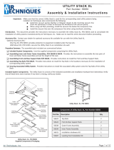
MOJAVE LT consists of the major components shown by Figure 1.
A single-stage pump, where all of the wetted metal parts are nickel plated or stainless steel.
A metal electrical enclosure that houses a VFD (Variable Frequency Drive), circuit breaker, and
PCB. A metal chassis for mounting components.
An aluminum heat exchanger to cool the exhaust air from the pump before it travels through
the exhaust vent.
The LCD touch screen provides the operational user interface for the MOJAVE LT system.
PRODUCT DESCRIPTION
Figure 1. MOJAVE LT Key Parts Identification
Front View Parts Location
Rear View Parts Location
Sight Glass
Heat
Exchanger
Air/Water
Separator
Assembly
Vacuum
Pump
Assembly
Pump Inlet
Manifold
Electrical
Box
Vacuum
Tube
Separator
Drain Port
Power Switch with
Circuit Breaker
Sight Glass
Exhaust Vent
Connection
LCD Touch
Screen Display
Vacuum Pump
Assembly
Heat
Exchanger
Air/Water
Separator
Assembly
Coarse
Strainer
Inlet Port
Leveling
Feet
Electrical
Box

Air Techniques, Inc.
Page
6
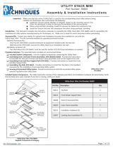
MOJAVE LT Dry Vacuum System Operation.
1. Air, water, and solids from the treatment room enter the system via the Inlet Port and are pulled
into the mechanical air/water separator assembly.
2. Air is then expelled to the outside vent through the pump heat exhaust.
3. Liquids and solids exit through the drain line of the separator.
4. The LCD touch screen provides the operational user interface for the MOJAVE LT system. It
monitors and displays the frequency, vacuum level, RPM reading and temperature as well as
recording the run time in hours.
Automatic Vacuum Adjustment.
When an instrument (suction tip) has been opened, the system senses an increase in vacuum demand
and responds by increasing the speed of the motor.
Conversely, when an instrument (suction tip) has been closed, the system reads the elevated vacuum level
and responds by slowing motor operation down due to decreased vacuum demand.
PRODUCT DESCRIPTION
Figure 2. MOJAVE LT, LT3M and LT5M, Functional Connection Points
Heat
Exhaust to
Outside
Vent
13
2
Liquids/Solids
from the Air/
Water Separator
to Sewer Drain
Gas/Liquids/Solids from the
Treatment Room
into Air/Water Separator

Page
7Air Techniques, Inc.
PRODUCT DESCRIPTION
General. For new installations it is recommended to follow the following guidelines:
Make sure to install the system in accordance with all local electrical and plumbing codes.
The suction line should not have any sharp right angle bends and must be sloped a minimum
of ¼ inch for every 10 feet toward the MOJAVE LT.
The drain on the base of the air/water separator must be connected to a vented or an open
floor drain capable of handling 5 gallons in 1 minute. Drain tube size 1 inch.
The drain line should be a full gravity drain. Avoid any sharp right angle bends.
Make sure to install the supplied exhaust vent assembly to the bottom end of the facility vent line.
The vent should be sloped ¼ inch per 10 feet towards the pump. Vent lines must be capable
of handling vapors and liquids.
The outside vent must be protected from rain and animals.
A flexible air exhaust hose is provided to connect to the 1½ inch diameter vent pipe and heat
exchanger. 1½ inch no-hub adapter is provided to secure hose to heat exchanger and pipe.
Run a network cable into the room where you will set up your Mojave to allow connection to
the Vision Monitor.
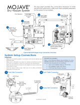
Figure 3. MOJAVE LT, LT3M and LT5M, Vacuum Pump Dimensions
Front View
Left Side View
20 in.
(51 cm)
16.5 in. (42 cm)
19.5 in. (50 cm) 24 in. (61 cm)

Air Techniques, Inc.
Page
8
Site Requirements
Electrical LT3M & LT5M Requirement
Voltage Rating Volts AC 220 Volts, Single Phase AC, 60 Hz
Voltage Minimum/Maximum 198/242 Volts AC
Wire Size AWG Minimum
Gauge #12 AWG
Minimum Circuit Breaker
Rating 20A
Incoming Power Hard wire Connection
(unit is supplied with a 6 foot BX cable)
Remote (Low Voltage Wiring) #18 AWG Wire Connection between the pump and
the Remote Switch Panel. Use of a high voltage switch not allowed.
Plumbing LT3M & LT5M Requirement
Exhaust Vent Pipe 1 ½” PVC Sch. 40
Minimum Suction Line Pipe 1” PVC Sch. 40 for LT3M 1 ½” PVC Sch. 40 for LT5M
Maximum Suction Line Pipe
(See note 2) 1 ½” PVC Sch. 40 for LT3M 2” PVC Sch. 40 for LT5M
Riser Pipe ½” PVC Sch. 40
Vacuum Line Termination 1 ½” Spigot
Drain Hose 1" Corrugated,
A full gravity drain is required.
NOTES
1. Recommended for all new installations.
2. Use maximum internal diameter for the main line when preparing any new installation.
Recommended Space Requirement
LT3M & LT5M
Height 20 in. (51 cm)
Width 24 in. (61 cm)
Depth 16.5 in. (42 cm)
INSTALLATION INFORMATION

Page
9Air Techniques, Inc.
INSTALLATION INFORMATION
Installation Notes.
Installation Layout Space. Figure 6 shows the requirements for the installation of MOJAVE
LT. Please note that all units are shipped with leveling feet set to lowest position. Heights can be
increased by 1 inch by adjusting the leveling feet. Refer to Figures 7 and 8 for connection details.
A. PUMP INSTALLATION SPACE - Area for MOJAVE LT pump in typical installation.
B. SEWER DRAIN - Provide a drain for the removal of waste liquids from the Air/Water Separator assembly.
Use an open drain pipe (1 ½ inch P-Trap with 1 inch air gap or floor sink) or a closed vented drain.
See Figure 6.
C. HEAT EXHAUST - Refer to Figure above and see Plumbing Requirements for the exhaust vent line required
for MOJAVE LT. Schedule 40 pipe can be used on MOJAVE LT.
D. PUMP ELECTRIC SERVICE - The MOJAVE LT pump is wired directly with a dedicated 220V, 20 AMP, single
phase 60 Hz circuit. If Main Circuit panel is not located in equipment room, a disconnect box with approved
ground is needed for each pump. Disconnect boxes should be mounted no more than 3 feet of the installation
center line.
E. OVERHEAD INSTALLATION VACUUM LINE - See Plumbing Requirements for MOJAVE LT connection.
F. SUB FLOOR INSTALLATION VACUUM LINE - See Plumbing Requirements for MOJAVE LT connection.
48"
4"
4"
20"
Sewer Drain
4"
MOJAVE LT
INSTALL
AREA
60"
1"
12"
24" for LT3 & LT5
44" for 2LT3 & 2LT5
36"
E
A
B
C
D
F
Figure 4. MOJAVE LT System Floor Plan

Air Techniques, Inc.
Page
10
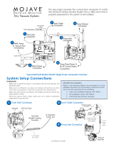
MOJAVE LT Connection Procedure. Using industry standard techniques, make the three
connections between the LT with supplied components from accessory kits Refer to Figure 7 for
the connection diagram and perform the following procedure.
1. Treatment Room Suction Line to Pump Inlet Connection. Refer to Figure 7, item (1) .
a. Install one connector adapter to the pipe (either overhead or sub floor) from the operatory.
b. Install the connector adapter into the flexible coupling connector on the LT.
c. Install the 1½" ID, clear hose cut for installation between the operatory suction line and
pump inlet and secure with two no-hub adapters.
2. Heat Exhaust Connection. Refer to Figure 7, item (2) for the location of the vent hose connection
at the pump heat exchanger output and the facility vent line. Make the heat exhaust connection by
performing the following procedure.
a. Exhaust Vent Assembly Installation. Refer to Figure 8 and install the Drip Leg and Exhaust
Vent Assembly to the bottom end of the facility vent line. Install a length of 1/4 inch OD
Urethane Tubing (P/N 51453) between the vent condensation drain port and facility sewer
drain.
b. Heat Exhaust Vent Connection. As shown by Figure 8, connect the vent hose
between the pump heat exchanger output and the facility vent line. Secure with no hub
adapters provided by the accessory kit.
Important: Make sure to efficiently use space by making connections as short and direct as possible
to meet your particular site requirements.
Make sure that all hose connections are straight and secure without any sharp bends or kinks.
Since the vacuum hose is rigid, make sure not to stress connections especially at the pump inlet.
INSTALLATION
Figure 5. MOJAVE LT Plumbing Connection
Heat
Exhaust to
Outside
Vent
1
3
2
Inlet Flexible Coupling
Connector
Liquids/Solids
from the Air/
Water Separator
to Sewer Drain

Page
11Air Techniques, Inc.
INSTALLATION
3. Drain to Facility Sewer Connection. Refer to Figure 8, item (3) for the location of the Air/
Water Separator drain. Use the 1-inch hose provided to connect the separator drain to the
facility sewer. As shown by Figure 8, the sewer connection can be made as either a closed
vented drain or open drain pipe method.
4. System Electrical Connections. Refer to the Electrical Connections section (See Figure 9.)
and connect the pump to 220V facility power. Refer to Figures 10 and 11 when connecting the
low power remote switch. Do not use a high voltage switch to turn power off remotely. Unit must
remain powered at all times.
Figure 6. MOJAVE LT Detail Plumbing Connection
Drip Leg and
Exhaust Vent
Assembly
3
OR
Open Drain
Pipe
Closed Vented
Drain
Connection to
Facility Sewer
Drain
1" Drain Hose
Clamp
No
Hub
2
Heat Exhaust
Connection to
Outside Vent
1½" Schedule 40
Facility Vent Line
No
Hub
10mm Vent
Condensation
Drain Port
Flex Tubing

Air Techniques, Inc.
Page
12
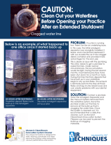
ELECTRICAL CONNECTIONS
Remove all power to the system prior to working
within the electrical box. Contacting high voltage
can cause serious injury or even death.
All systems must be wired directly from
an electrical box that complies with
local electrical codes.
Figure 8. Remote Switch Connection to Main Board
Remote Switch Connections.
As shown by Figure 10, connections are made via connectors J4 and J6 of the main board.
VDC Connections.
Make the 6 VDC connections shown by Figure 11, View A, for Remote Panel Switch #53202-1
provided by Air Techniques. Make the 24 VDC connections shown by Figure 11, View B, for Remote
Panel Switch #53201-1. When using a switch not provided by Air Techniques, all remote system
status indication is lost.
Figure 7. MOJAVE LT Power Connection
MOJAVE LT Pump Direct Power Connection.
Each unit is wired directly to an dedicated 220V, 20 AMP single
phase 60 Hz circuit via a disconnect box with approved ground.
BLACK
WHITE
Disconnect boxes should be mounted no
more than 3 feet of the installation center
line.
Figure 10 shows the wiring of the electrical BX
cable used to connect the LT directly to facility
input power.
Supplied 6-Foot BX Cable
from Electrical Box of Pump
GREEN YELLOW
STRIPE
(L2)
(L1)
(GND)
J10
AUX_ALARM
J6
J4
ORN
YEL
RED
BRN1
BRN2
AUX
J9
J14
ETH
To
Remote
Switch
Connect by
Wire Color
Important: Use CAN BUS Termination Resistor, P/N 85133, when making
tandem pump connections.

Page
13Air Techniques, Inc.
YEL
BRN
ORN
BRN 2
ORN
YEL
RED
BRN 1
Remote Switch
Terminal Board
Interconnect Cable
Interconnect Cable
Interconnect Cable
GRN
Remote Switch
GREEN ONLY, 24VDC
P/N 53201-1
Important: Terminals RED & BRN 1 are not used when
making the 3-wire connection.
NOT
USED
View B. 3-Wire Green Indicator Only 24 VDC Remote Switch Installation
ELECTRICAL CONNECTIONS
Figure 9. 3-Wire and 4-Wire Remote Switch Connection
Note: Use 18 Gauge for interconnect cable to connect between unit
and remote switch.
YEL
ORN
BRN 2
ORN
YEL
RED
BRN 1
Remote Switch
Terminal Board Remote Switch
Interconnect Cable
Interconnect Cable
BRNInterconnect Cable
Interconnect Cable RED
YEL
GRN
D2
SPDT
BI COLOR SWITCH, 6VDC
P/N 53202-1
Important: Terminal BRN 2 is not used when
making the 4-wire connection.
NOT USED
View A. 4-Wire Green & Yellow Indicators 6 VDC Remote Switch Installation

Air Techniques, Inc.
Page
14
OPERATING INFORMATION
General.
The vacuum level is factory preset at 8 InHg. This vacuum set point is adjustable from 8.0 to
10.0 inHg in increments of 0.5 inHg via the touch screen.
System operation is automatically controlled. Parameters can be adjusted via the touch screen
The system is capable of running continuously and should be put into standby mode when not
in use.
The system may be turned ON or put into standby mode from a single, convenient location
within the dental office using an optional Remote Control Panel switch.
Figure 10. MOJAVE LT Front Panel Controls and Indicators
Mojave LT Standby and Run modes must be toggled from either the LCD touchscreen or the
optional low voltage remote switch. The Mains Circuit Breaker must remain in the ON position
at all times for the Self Diagnostic feature to run properly. Unit cannot be turned on/off using a
high voltage switch connected to the main power source. Failure to do so will VOID the warranty.
Power
Circuit Breaker
Touch
Screen

Page
15Air Techniques, Inc.
OPERATING INFORMATION
START UP BY TOUCH SCREEN
1. Set the motor Mains Circuit Breaker in the
ON position.
2. Observe that the color touch screen illuminates
and depress the blue Standby button.
3. Observe that the Standby button changes to a
green Running button, that the unit is running and
the Vacuum widget shows increasing pressure.
START UP BY OPTIONAL REMOTE SWITCH
1. Set the motor Mains Circuit Breaker to the
ON position.
2. Observe that the when in Standby with no errors
the push button indicator is extinguished.
Note a: Depending on the site installation, the
remote switch can be either a Bi-Color LED
6VDC switch (included) or a single LED 24
VDC switch.
Refer to the tables below for the LED
conditions for each switch during operation.
3. Depress the push button switch and observe that
the associated indicator illuminates as listed
for the corresponding switch.
6V DC Bi-Color Green / Yellow Indicators (See Note a.)
Bi-Color LED Condition Switch
Position Condition Description
None Out Standby, No errors
Solid Green In Running, No errors
Flashing Yellow Out Standby, Error present
Alternating Green / Yellow In Running, Error present
24V DC Green Indicator Only (See Note a.)
Green LED Condition Switch
Position Condition Description
None Out Standby, No errors
Solid Green In Running, No errors
Flashing Green – Slow Out Standby, Error present
Green – Fast In Running, Error present
Optional Remote Control Panel
Control Panel
2
Color LCD Touch Screen Display
Control Panel
3
2
Pump Power
On/Off Switch and
Circuit Breaker

Air Techniques, Inc.
Page
16
Note: The motor power circuit breaker must be kept in the ON position to operate the color
LCD touch screen display. See Operating Information on page 15.
All MOJAVE LT units have a color LCD touch screen display located on the front control box panel.
This display is used to start the unit and show system operating status. It also serves as an input for
controlling operation and adjusting system parameters.
The display shows two screens during normal operation; a Home Screen and a Settings Screen. The
Home Screen is used to start and monitor operation of the MOJAVE LT, while the Settings Screen
allows changes to operating parameters.
The screens are comprised of operation Buttons, Navigation Buttons and Widgets as described below.
TOUCH SCREEN CONTROLS
Operation Buttons
Standby Button - Home Screen Standby Button that when blue, indicates the system is in
the "Standby" mode. When pressed, this switch starts the compressor operation.
Running Button - Home Screen Standby Button that when green indicates the system is in
the "Running" mode. When pressed, this switch stops MOJAVE LT operation and returns
to the "Standby" (blue button) mode.
Error Button - Home Screen Standby Button that when red indicates an error is present
causing the MOJAVE LT to shut down operation.
Navigation Buttons - located on the bottom of the screen these buttons allow the user to migrate
within a screen by going to the next screen level or to transfer between the Home Screen and a
Settings Screen.
Widget - an element of a graphical user interface (gui) that is used to display information during
vacuum operation. The Home Screen normally shows the Vacuum Widget while the Motor Frequen-
cy, Separator RPMs, Voltage and Temperature widgets are accessed by pressing the Next Navigation
Button.
Vacuum Widget
Standby Button
Navigation Buttons

Page
17Air Techniques, Inc.
TOUCH SCREEN CONTROLS
1. HOME SCREEN
a. STANDBY BUTTON / VACUUM SCREEN
i. Standby Button
- Running: Motor and separator run to maintain the set vacuum level of 8.0 to 10.0 inHg.
- Standby: Motor and separator are not running.
- Error: Motor and separator do not run.
ii. Vacuum Widget - Displays current vacuum level.
b. PUMP / SEPARATOR SCREEN
i. Pump Frequency Widget - Displays current frequency level with min/max range indicator.
ii. Separator RPM Widget - Displays current RPM value with min/max range indicator.
c. VOLTAGE / TEMPERATURE SCREEN
i. Voltage (V) Widget - Current line voltage with min/max range indicator.
iI. Temperature (οF) Widget - Current ambient temperature of room with max temperature limit
indicator.
Vacuum Indicator
Vacuum Digital Readout
Standby
Button
Frequency Digital Readout
Frequency Indicator
Note: Indicator will turn red when
room temperature exceeds 105ο F
Temperature
Digital Readout
Max Temperature
Range Indicator
Temperature Indicator
Voltage Min/Max
Range Indicator
Voltage Digital Readout
Voltage Indicator
Frequency Min/Max
Range Indicator
RPM Digital Readout
RPM Indicator
RPM Min/Max
Range Indicator

Air Techniques, Inc.
Page
18
TOUCH SCREEN CONTROLS
2. SETTINGS SCREEN
a. INFORMATION
i. Model - Air Techniques model number.
ii. SN - Unit serial number.
iii. PCB - Indicates control board serial number.
iv. Firmware - Indicates latest installed firmware and revision.
v. VFD Code - Indicates VFD Code number.
b. ACCESS
i. User - Default setting on startup, this access level should be used when unit is not being
serviced by a technician. Set level by pressing the radio button.
ii. Technician - This access level is used when unit is being serviced by a technician to access all
option choices. Set level by pressing the radio button.
Note: Access will save on exit by either HOME or BACK buttons
c. PARAMETERS
i. Set Point - Sets vacuum level between 8-10 inHg in 0.5 inHg increments by pressing up or
down arrows. Press the SAVE button to accept setting.
d. DATE / TIME
i. Date - Sets to current date. Set date by pressing up or down arrows above or below each
digit, then press the SAVE button.
Note: When the time zone (UTC) is reset, the time setting may need to be set to match location.
ii. Time - Sets current time for selected time zone. Set time by pressing up or down arrows above
or below each digit, then press the SAVE button.
iii. Time Zone - Sets time zone. Set appropriate UTC (see table) by pressing up or down arrows
above or below each digit. Press the SAVE button and then power cycle (power off then on)
device to save setting. After completing power cycle, verify the time matches location.
SETTINGS SCREEN
Page Number
Scroll Button
Option Choice Page Indicator
Sub-Folder Address

Page
19Air Techniques, Inc.
TOUCH SCREEN CONTROLS
e. NETWORK
i. Hint: - Password “Hint”
ii. DHCP: - Indicates DHCP of connected network
iii. IP-Address: - Indicates IP-Adress of connected network
iv. Netmask: - Indicates Netmask of connected network
v. Gateway: - Indicates Gateway of connected network
vi. MAC Address: - Indicates MAC address of unit
f. STATISTICS
i. On-Time - Shows time that unit has been powered on (hours)
ii. Run-Time - Shows time that unit has been running (hours)
g. ALARM HISTORY
Shows the last forty (40) alarms triggered. Push any listed ALARM button to get details of alarm,
such as suggested tasks and date alarm was triggered.
Time Zones Currently Being Used in United States
Time
Offset
Time Zone Example
City
Abbreviation Name
UTC - 5 EST Eastern Standard Time New York
UTC - 6 CST Central Standard Time Chicago
UTC - 7 MST Mountain Standard Time Salt Lake City
UTC - 8 PST Pacic Standard Time Los Angeles
UTC - 9 AKST Alaska Standard Time Anchorage
UTC - 10 HAST Hawaii-Aleutian Standard Time Honolulu

Air Techniques, Inc.
Page
20
a. WARNINGS
TOUCH SCREEN CONTROLS
ALARMS
MOJAVE LT checks operation via the Intelligent Monitoring System and alerts the user to problems by
displaying Warnings or Errors in the upper left corner of the Home Screen. Warnings notify the user
of conditions effecting operation while Errors are critical problems disabling operation. As shown
below, explanation of the Warning or Error is expanded by pressing the displayed alert. Also refer to
TROUBLESHOOTING, page 24, to correct additional problems.
Home Screen Showing Warning Example Warning Screen
Line voltage
Warning
Alert Example
i. Line voltage is out of range. Contact Technician.
ii. Room temperature is too high.
iii. Room temperature is too low.
iv. Vacuum level is greater than 1.0 inHg over setpoint.
v. Vacuum level is less than 0.5 inHg over setpoint.
/