Page is loading ...

EN
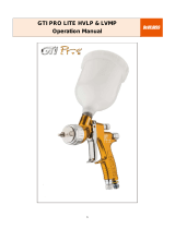
OperationManual
COBRA3C–AutomaticSprayGun
SB-E-2-741 ISS.03
II 2 G X T6

2©2014FinishingBrandsUKLtd.
Table of Contents
Topic Page
Characteristics 3
EC Declaration of Conformity 3
Safety Warnings 4
Model Part Numbers 5
- Table 1: Air Cap Range 5
- Table 1: Fluid Nozzle & Needle Range 5
Specification & Materials of Construction 5
Exploded View 6
Parts List 7
Dimensions 8
Air Connection 9
Maintenance 10
Body Removal 10
Piston/Needle Removal 11
Needle Packing Removal 11
Fluid Nozzle Removal 12
Manifold O-ring and Connector Removal/ Assembly 12
Setting Micrometer 13
Air Cap Indexing (Optional) 13
Troubleshooting 14
Accessories 16
Warranty 16

3©2014FinishingBrandsUKLtd.
Manual Operation
Cobra 3C Automatic Spray gun
Important - Read and follow all instructions and Safety Precautions
before using this equipment.
CHARACTERISTICS:
This automatic spray gun complies with ATEX regulations 94/9/EC, protection
level II 2 G X T6, suitable to use in zones 1&2.
This Cobra 3 is a production spray gun suitable for use with automatic and
semi-automatic machines in HVLP or Trans-Tech applications.
Remotely positioned valves (supplied by user) control all air supplies for
atomisation, fan size and triggering.
To handle a wide range of coating materials this spray gun is made from high
grade stainless steel.
IMPORTANT: These Spray guns are suitable for use with both water based
and solvent based coating materials. These guns are not designed for use
with highly corrosive and/or abrasive materials and if used with such materials
it must be expected that the need for cleaning and/or replacement of parts will
be increased. If there is any doubt regarding the suitability of a specific
material, contact your DeVilbiss Distributor or DeVilbiss direct. NOTE: This
gun is not to be used with halogenated hydrocarbon solvents or cleaning
agents such as 1, 1, 1,-Trichloroethane or methylene chloride. These solvents
can react with the aluminium components used in this gun. The reaction can
become violent and lead to an equipment explosion.
Fluid Tips and Needles are only available in hardened stainless steel.
Pressure feed material supply can be re-circulated or direct.
The needle adjustment knob has a micrometer control allowing fine and
accurate fluid flow control.
EC Declaration of Conformity
FinishingBrandsUKLimitedreservestherighttomodifyequipmentspecificationwithoutprior
notice
We, Finishing Brands UK Limited, Ringwood Rd, Bournemouth, Dorset, BH11 9LH, UK as
the manufacturer of the spray gun model Cobra 3C, declare, under our sole responsibility that
the equipment to which this document relates is in conformity with the following standards or
other normative documents:
BS EN 12100:2010, BS EN 1953:2013; and thereby conforms to the protection requirements of
Council Directive 2006/42/EC relating to Machinery Safety Directive, and;
EN 13463-1:2009, Council Directive 94/9/EC relating to Equipment and Protective Systems
Intended for Use in Potentially Explosive Atmospheres protection level II 2 G X T6.
D.Smith General Manager
14th March 2014

4©2014FinishingBrandsUKLtd.
Safety Warnings
Fire and explosion
Solvents and coating materials can be highly flammable or combustible when sprayed.
ALWAYS refer to the coating material supplier’s instructions and COSHH sheets
before using this equipment.
Users must comply with all local and national codes of practice and insurance company
requirements governing ventilation, fire precautions, operation and house-keeping of working
areas.
This equipment, as supplied, is NOT suitable for use with Halogenated Hydrocarbons.
Static electricity can be generated by fluid and/or air passing through hoses, by the spraying
process and by cleaning non- conductive parts with cloths. To prevent ignition sources from
static discharges, earth continuity must be maintained to the spray gun and other metallic
equipment used. It is essential to use conductive air and/or fluid hoses.
Personal Protective Equipment
Toxic vapours – When sprayed, certain materials may be poisonous, create irritation or are
otherwise harmful to health. Always read all labels, safety data sheets and follow any
recommendations for the material before spraying. If in doubt, contact your material
supplier.
The use of respiratory protective equipment is recommended at all times. The type of
equipment must be compatible with the material being sprayed.
Always wear eye protection when spraying or cleaning the spray gun.
Gloves must be worn when spraying or cleaning the equipment.
Injection Hazard – Spray from the gun, hose leaks or ruptured components can inject fluid
through skin into the body and cause extremely serious injury including poisoning. GET
IMMEDIATE MEDICAL ATTENTION. INFORM THE DOCTOR WHAT TYPE OF MATERIAL
WAS INJECTED.
Do not put fingers or hand over the spray tip.
Replace all worn, damaged or loose parts immediately.
Training – Personnel should be given adequate training in the safe use of spraying
equipment. Misuse
Never aim a spray gun at any part of the body.
Never exceed the max. Recommended safe working pressure for the equipment.
The fitting of non-recommended or non-original spares may create hazards.
Before cleaning or maintenance, all pressure must be isolated and relieved from the
equipment.
The product should be cleaned using a gun-washing machine. However, this equipment
should not be left inside gun-washing machines for prolonged periods of time.
Noise Levels
The A-weighted sound level of spray guns may exceed 85 dB (A) depending on the set-up
being used. Details of actual noise levels are available on request. It is recommended that
ear protection is worn at all times when spraying.

5©2014FinishingBrandsUKLtd.
Model Part Numbers
CBA3C - ##### - ### N
e.g. CBA3C-590-085N
Where:-
590= 590 Trans-Tech Air Cap
085=0.85mm Fluid Nozzle and Needle
N= Hardened Fluid Nozzle and Needle
e.g. CBA3C-590HV-10N
Where:-
590HV= 590HV HVLP Air Cap
10= 1.0mm Fluid Nozzle and Needle
N= Hardened Fluid Nozzle and Needle
Table 1: Air Cap Range
Air Cap Type Part No. Technology Marking On Cap
590 SP-100-590-K Trans-Tech COM 590
590 HV SP-100-590HV-ADV-K HVLP 590 HV
Table 2: Hardened Fluid Nozzle and Needle Range
Fluid Nozzle Size
mm Hardened
Fluid Nozzle Hardened
Fluid Needle Marking on
Fluid Needle
0.7 SP-259N-07-K SPA-353-07-K 3C 07
0.85 SP-259N-085-K SPA-353-085-K 3C 085
1.0 SP-259N-10-K SPA-353-10-K 3C 10
Specification & Materials of Construction
Thread Pressure
Air inlet Pattern + Length (P1) 1/8” BSP Female P1 Max 12 bar / 174 psi
Fluid inlet & fluid recirculation (P2) 1/8” BSP Female P2 Max 15 bar / 218 psi
Cylinder/trigger 1/8“ BSP Female 3.5 to 6 bar / 51 to 87 psi
Maximum temperature in use 40° C / 104°F
Spray gun weight 496 g / 17.5 oz.
Materials of construction
Gun body / Manifold / Micrometer Assembly 303 Stainless steel, 6082 Aluminium Alloy
Tip / Needle Hardened 303 Stainless steel.
Fluid seals Viton Extreme, Polyethylene, PTFE
Type of
Gun Air Cap Type
(See Table 1)
Fluid Nozzle Size
(See Table 2)
Hardened

6©2014FinishingBrandsUKLtd.

7©2014FinishingBrandsUKLtd.
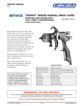
PARTS LIST
REF. DESCRIPTION PART NO. QTY.
1 AIR CAP ASSEMBLY SEE TABLE 1, p5 1
2 FLUID NOZZLE KIT SEE TABLE 2, p5
3 FLUID NOZZLE - 1 (a)
4 SEPARATOR - KIT OF 5 SP-626-K5 1 (a)
5 BODY - 1
6 NEEDLE PACKING KIT SPA-408-K
7 NEEDLE PACKING - KIT OF 2 SPA-118-K2 1 (b)
8 PACKING NUT - 1 (b)
9 O-RING - 1 (b)
10 PISTON ASSEMBLY
SPA-409-K
11 E CIRCLIP 1
12 O-RING 1
13 PISTON 1
14 O-RING 1 (c)
15 FLUID NEEDLE SEE TABLE 2, p5 1
16 PISTON SPRING SPA-123-K 1
17 MICROMETER ASSEMBLY SPA-405-K 1
18 MANIFOLD ASSEMBLY SPA-410-K
19 MANIFOLD 1 (d)
20 SCREW KIT
SPA-411-K
21 GRUB SCREW 2 (d)
22 M4 TORX SCREW 1 (d)
23 O-RING KIT
SPA-412P-K
24 O-RING 2 (d)
25 O-RING 3 (d)
26 ELBOW FITTING - KIT OF 2 SPA-136-K2 2 (d)
27 PUSH FITTING - KIT OF 3 SPA-137-K3 3 (d)
a=IncludedwithFluidNozzleKit
b=IncludedinNeedlePackingKitSPA‐408‐K
c=IncludedonFluidNeedle
d=IncludedwithManifoldAssemblySPA‐410‐K

8©2014FinishingBrandsUKLtd.
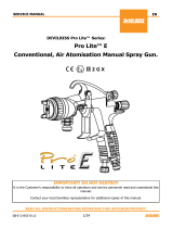
Dimensions
A - FLUID INLET (x2)
1
/8” BSP
B- TRIGGER / CYLINDER AIR INLET 1/8” BSP
C- LENGTH AIR INLET 1/8” BSP
D- PATTERN AIR INLET 1/8” BSP
E- M6 MOUNTING HOLES (x2)
F- M4 BODY / MANIFOLD CONNECTION HOLE

9©2014FinishingBrandsUKLtd.
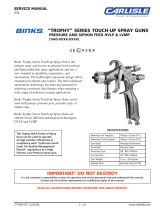
Air Connection
Maintenance
Key to Symbols
Fan air supply
Pressure regulator
0-1 Bar / 0-15 psi recommended
12 Bar / 174 psi maximum
Trigger / Cylinder Air
3/2 Valve
3.5-6 Bar / 51-87 psi
Atom air supply
Pressure regulator
0-1 Bar / 0-15 psi recommended
12 Bar / 174 psi maximum
Lubricate with Petroleum Grease Tool type & size required
Component direction arrow
For dis-assembly and sequence
number. (Reverse sequence to
Re-assemble).
Important: The spray gun must be earthed to dissipate any electrostatic charges which may be
created by fluid or air flows. This can be achieved through the spray gun mounting, or conductive
air/fluid hoses. Electrical bond from the spray gun to earth should be checked with an Ohm meter.
A resistance of less than 106 Ohms is recommended
1

10©2014FinishingBrandsUKLtd.
MAINTENANCE
Body Removal
T20
1
2
WARNING – Check all air and fluid pressure is removed before starting maintenance.
1.8-2.0 Nm
1.3-1.5 lbf.ft

11©2014FinishingBrandsUKLtd.
Piston/Needle Removal
``
Needle Packing Removal
1
2
2 1
3
4
Note: O-Ring assembled
into 2nd undercut.
Tighten Packing nut to
torque of 5 Nm (44 Ibf/in)
when re-assembling.

12©2014FinishingBrandsUKLtd.
Fluid Nozzle Removal
Manifold O-Ring and Connector Removal/Assembly
Tighten nozzle to torque of 15 Nm
(133 Ibf/in) when re-assembling.
10mm
1
2
3

13©2014FinishingBrandsUKLtd.
Setting Micrometer Zero (0mm Needle stroke)
Indexing Air Cap 90° (Optional)
1
3
2
4
Rotate barrel using
key as a lever until the
horizontal scale is in
line with “0” on the
knob. Re-tighten
screw.
Screw in knob until it
touches stop.
Note: Do not over
tighten.
1.5mm
3
5
4
Orientate Air Cap and
engage pins into
location holes in gun.
Remove Snap Ring holding Air Cap into
Retaining Ring with a small screwdriver
blade; assemble optional Indexing Ring
(SPA-112) onto the Air Cap by engaging
p
ins into the location holes.
1
2

14©2014FinishingBrandsUKLtd.
Troubleshooting
Possible Problems in Operation
CONDITION CAUSE CORRECTION
Spray Pattern
Heavy top or
bottom pattern.
Heavy right or left
side pattern.
Horn holes plugged.
Obstruction on top or bottom of fluid
nozzle.
Cap and/or nozzle seat dirty.
Left or right side horn holes plugged.
Dirt on left or right side of fluid
nozzle.
Clean with non-metallic point.
Clean.
Clean.
Clean with non-metallic point.
Clean.
Remedies for the top-heavy and bottom-heavy patterns:
1. Determine if the obstruction is on the air cap or the fluid nozzle. Do this by making a test spray pattern. Then,
rotate the cap one-half turn and spray another pattern. If the defect is inverted, obstruction is on the air cap.
Clean the air cap as previously instructed. Also check for dried paint just inside the cap centre hole opening;
remove by washing with solvent.
2. If the defect is not inverted, it is on the fluid nozzle. Clean nozzle. If problem persists, renew nozzle.
Heavy centre
pattern.
Fan Air pressure set too low.
Material too thick.
Increase Fan Air pressure to
achieve correct pattern.
Thin to correct consistency.
Split spray
pattern.
Fluid Flow set too low.
Fan Air pressure set too high.
Increase Fluid Flow to achieve
correct pattern.
Decrease Fan Air pressure to
achieve correct pattern.
Jerky or
fluttering spray.
Material level too low.
Obstruction in fluid passage.
Refill.
Back flush with solvent.

15©2014FinishingBrandsUKLtd.
Possible Problems in Operation (cont.)
Fluid Starved spray
pattern.
Inadequate material flow.
Increase Fluid Flow.
Change to larger fluid nozzle size.
Check hose for blockage.
Excessive overspray.
Air pressure too high.
Gun too far from work surface.
Reduce air pressure.
Adjust to correct target distance.
Dry spray.
Air pressure too high.
Gun too far from work surface.
Gun motion too fast.
Fluid flow too low.
Reduce air pressure.
Adjust to correct distance.
Slow down.
Increase Fluid Flow or use larger nozzle
size.
Runs and sags.
Too much material flow.
Material too thin.
Motion too slow.
Reduce Fluid Flow or change to smaller
fluid nozzle and fluid needle size.
Mix correctly or apply light coats.
Increase Gun Traverse speed.
Leakages
Fluid leaking from
Detection hole. Packing or Fluid Needle worn. Replace.
Fluid leaking or dripping
from front of gun.
Fluid nozzle or fluid needle worn or
damaged.
Foreign matter in fluid nozzle.
Fluid needle dirty or stuck in needle
packing.
Wrong size fluid needle or fluid nozzle.
Replace fluid nozzle and fluid needle.
Clean.
Clean.
Replace fluid nozzle and fluid needle.
Fluid leaking between
the Spray Gun and the
Manifold.
O-Rings damaged or missing.
Torx screw not tight.
Replace O-Rings using kit SPA-412-K.
Tighten Torx screw or replace using kit
SPA-411-K.
Assembly Faults
Spray Gun is loose
when assembled onto
Manifold. Torx screw not tight. Tighten Torx screw 1.8-2.0 Nm (1.3-1.5
lbf.ft) or replace using kit SPA-411-K.

16©2014FinishingBrandsUKLtd.
WARRANTY
This product is covered by Finishing Brands UK Limited one year warranty.
Finishing Brands UK Limited,
Ringwood Road,
Bournemouth,
BH11 9LH,
UK.
Tel.No: 01202 571111
Fax No: 01202 581940
Website address: http:// www.finishingbrands.eu
Registered office:
Finishing Brands UK Limited,
400, Capability Green,
Luton,
Bedfordshire,
LU1 3AE,
UK.
Registered in England No: 07656273
Vat No: GB 113 5531 50
ACCESSORIES
Mounting Bar SPA-406-K
Fluid Needle
Removal Tool SPA-407-K
1.5mm Allen
Key SPN-10-K 2mm Allen
Key SPN-11-K
T20 Torx Key SPN-8-K2 Indexing Ring SPA-112
10mm Spanner - 4mm Allen
Key -
/