RAM 2017 ProMaster Reference guide
- Category
- Cars
- Type
- Reference guide
This manual is also suitable for


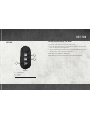
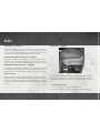
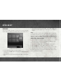
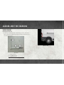
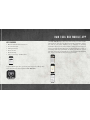
KEY FOB
Locking And Unlocking The Doors
• Push the lock button once to lock all the doors.
• Push the unlock button once to unlock the driver’s door only and
twice to unlock the passenger door.
• To lock or unlock the cargo area doors, push the cargo area door lock
switch located on the driver door trim panel.
Please refer to your Owner’s Manual at
www.ramtruck.com/en/owners/manuals/ for further information.
Key Fob
1 — Cargo Doors
2 — Unlock
3 — Lock
KEY FOB

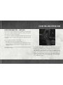
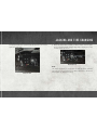
Parksense Rear Park Assist
If an object is detected behind the rear bumper while the vehicle is in
REVERSE, a chime will sound. The chime rate will change depending
on the distance of the object from the rear bumper, getting faster as the
object approaches. The chime will sound continuously when the
distance between the vehicle and the detected object is less than
12 inches (30 cm).
Parkview Rear Back-Up Camera
You can see an on-screen image of the rear of your vehicle whenever the
gear selector is put into REVERSE. The ParkView Rear Back-Up
Camera image appears on the display screen located on the center
stack of the instrument panel.
NOTE:
If the display screen appears foggy, clean the camera lens located on
the top rear of the vehicle below the center light.
For further information and applicable warnings and cautions, please refer
to your Owner’s Manual on
www.ramtrucks.com/en/owners/manuals.
PARKSENSE

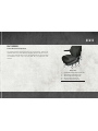
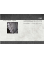
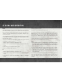
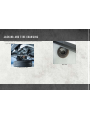
Seat Features
Forward And Rearward Adjustment
The adjusting bar is at the front of the seat, near the floor. Pull the bar
upward to move the seat forward or rearward. Release the bar once the
seat is in the desired position. Then, using body pressure, move forward
and rearward on the seat to be sure that the seat adjusters have
latched.
Driver’s Seat
1 — Forward/Rearward Adjustment Bar
2 — Front Height Adjusting Lever
3 — Rear Height Adjusting Lever
4 — Recliner Adjusting Knob
5 — Lumbar Adjustment Knob
SEATS

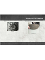
Lumbar Support — If Equipped
This feature allows you to increase or decrease the amount of lumbar
support. The lumbar control knob is located on the rear upper outboard
side of the driver's seatback. Rotate the control forward to increase and
rearward to decrease the desired amount of lumbar support.
Height Adjustment (Without Swivel Seat) — If Equipped
The height adjusting levers are located on the center outboard side of
the seat. Lift up on the front lever to adjust the front of the seat up or
down. Lift up on the rear lever to adjust the rear of the seat up or down.
Height Adjustment (With Swivel Seat) — If Equipped
The height adjusting knobs are located on the center outboard side of
the seat. Rotate the front knob to adjust the front of the seat up or
down. Rotate the rear knob to adjust the rear of the seat up or down.
Recliner Adjustment
The recliner knob is on the rear outboard side of the seat. To recline the
seatback, lean back, rotate the knob rearward to position the seatback
as desired. To return the seatback to its normal upright position, lean
forward, rotate the knob forward until the seatback is in the upright
position.
Heated Seats — If Equipped
On some models, the front driver and passenger seats may be equipped
with heaters in both the seat cushions and seatbacks. The controls for
the front heated seats are located on the lower outboard side of the
seat.
To Turn Heated Seats On/Off
1. Push the switch once to turn on the heated seats.
2. Push the switch a second time to shut the heating elements off.
Heated Seat Switch
SEATS

Adjustable Armrests — If Equipped
The seat adjustable armrest can be raised and adjusted for height.
Underneath the front of the armrest is the adjuster wheel which will
adjust the height of the armrest up or down.
Turn the adjuster wheel to the right or left to adjust the height of the
armrest up or down.
Adjuster Wheel
SEATS

Power Folding Mirrors — If Equipped
The switch for the power folding mirrors is located on the driver’s door
panel below the power mirror controls. The power fold mirrors are
designed to be folded and unfolded using the power folding switch.
Operation
• Push the switch to the right and the mirrors will fold in.
• Push the switch to the left and the mirrors will return to the normal
driving position.
To Reset The Power Folding Mirror
1. Push the switch to the right and the mirrors will fold in to the closed
position.
2. Push the switch to the left and the mirrors will return to the open
position.
NOTE:
The intended use of the power fold mirrors is by pushing the buttons to
fold and unfold the mirrors. Only manually fold the mirrors when
necessary.
Forward Folding
Mirrors can be folded forward manually or by accidental impact. In this
case, it is possible to restore to position both ways, manually and
electrically.
MIRRORS

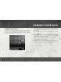
Instrument Cluster Display
The instrument cluster display features a driver interactive display that
is located in the instrument cluster. Pushing the controls on the left
side of the steering column allows the driver to select vehicle informa-
tion and Personal Settings.
• Push the up arrow button to scroll upward through the main menus
(Menu, Outside Temperature Display, Trip Functions, Date, Time)
and sub menus.
• Push the down arrow button to scroll downward through the main
menus and sub menus.
• Push the MODE button for access to main menus, sub menus or to
select a personal setting in the setup menu. Push and hold the MODE
button for two seconds to reset features.
• Push and hold the MODE button for two seconds to reset displayed/
selected features that can be reset.
For further information and applicable warnings and cautions, please refer
to your Owner’s Manual at
www.ramtrucks.com/en/owners/manuals.
Instrument Cluster Display Controls
INSTRUMENT CLUSTER DISPLAY

Speed Beep
This function makes it possible to set the vehicle speed limit (MPH
or km/h). When this limit is exceeded the driver is immediately alerted.
To set the desired speed limit, proceed as follows:
• Briefly press the MODE button: the display will show the wording
(Speed Beep)
• Push button or to select speed limit activation (On) or deactivation
(Off)
• If the function has been activated (On), push the up or down arrow
buttons to select the desired speed limit and then push MODE to
confirm.
NOTE:
Setting is possible between 20 and 120 MPH (30 and 195 km/h),
according to the previously set unit. The setting will increase/decrease
by 5 units each time the up or down arrow button is pushed. Hold down
either up or down arrow button to automatically increase/decrease the
setting rapidly. Complete the adjustment with single pushes of the button
when you approach the desired value.
• Push the MODE button briefly to return to the menu screen or hold
the button down to return to the standard screen without storing.
To cancel the setting, proceed as follows:
• Briefly push the MODE button, (On) will flash on the display
• Push the down arrow button, (Off) will flash on the display
• Push the MODE button briefly to return to the menu screen or hold
the button down to return to the standard screen without storing.
For further information and applicable warnings and cautions, please
refer to your Owner’s Information.
Instrument Cluster Display Controls
SPEED BEEP

Electric Park Brake (EPB) — Diesel Only
Your vehicle is equipped with an Electric Park Brake System (EPB) that
offers simple operation, and some additional features that make the
park brake more convenient and useful.
The park brake is primarily intended to prevent the vehicle from rolling
while parked. Before leaving the vehicle, make sure that the park brake
is applied.
You can engage the park brake in two ways:
• Manually, by applying the park brake switch.
• Automatically, by the Auto Park Brake feature whenever the vehicle
speed is below 1.25 mph (2 km/h) and the ignition switch is in the
STOP/OFF position.
The park brake switch is located on the instrument panel to the right of
the instrument cluster.
To apply the parking brake manually, pull and tilt the top of the switch
away from the instrument panel momentarily. You may hear a mechani-
cal sound while the parking brake operates; this is normal operating
noise. Once the parking brake is fully engaged, the BRAKE warning
lamp in the instrument cluster and an indicator on the switch will
illuminate. The park brake can be applied even when the ignition
switch is OFF; however, it can only be released when the ignition switch
is in the ON/RUN position.
Electric Park Brake Switch
STARTING AND OPERATING

NOTE:
The EPB fault lamp will illuminate if the EPB switch is held for longer
than 20 seconds with a vehicle speed less than 1.25 mph (2 kph), or
60 seconds with a vehicle speed greater than 1.25 mph (2 kph), in
either the released or applied position. The light will extinguish upon
releasing the switch.
The park brake will automatically engage whenever the ignition switch
is turned OFF and the vehicle speed is below 1.25 mph (2 km/h) via the
Auto Park Brake feature.
The electric park brake will automatically release if the engine is on and
all following conditions are met:
1. Driver's weight is detected on the driver's seat.
2. Driver's seat is locked in forward direction (if equipped with swivel
seat).
3. Transmission is in forward or reverse gears.
4. The accelerator pedal is pressed.
Or
1. Driver’s weight is detected on the driver’s seat.
2. Driver’s seat is locked in forward direction (if equipped with swivel
seat).
3. Transmission is moved from NEUTRAL to DRIVE or REVERSE
gears.
4. Brake pedal is pressed.
5. Vehicle is on a slope less than 5 percent.
To release the park brake manually, the ignition switch must be in the
ON/RUN position. Put your foot on the brake pedal, then push the
parking brake switch down momentarily. Once the park brake is fully
disengaged, the BRAKE warning lamp in the instrument cluster and
the LED indicator on the switch will extinguish.
If during drive away the driver pulls the EPB switch (apply position) the
drive away is halted and EPB will be reapplied.
NOTE:
• When parking on a hill, it is important to turn the front wheels toward
the curb on a downhill grade and away from the curb on an uphill
grade. The parking brake should always be applied whenever the
driver is not in the vehicle.
• The Electronic Park Brake system communicates with the Driver
Presence Detection sensor installed in the driver seat. The use of
seat covers or seat accessories could prevent the Electronic Park
Brake system from working properly and result in unintended
vehicle movement.
If exceptional circumstances should make it necessary to engage the
park brake while the vehicle is in motion, a buzzer repeats until the
park brake switch is released or vehicle speed is below 1.25 mph
(2 km/h).
STARTING AND OPERATING

To disengage the park brake while the vehicle is in motion, release the
switch. If the vehicle is brought to a complete stop using the park
brake, when the vehicle reaches approximately 1.25 mph (2 km/h) the
parking brake will remain engaged.
In the unlikely event of a malfunction of the Electric Park Brake
system, a yellow triangle EPB fault lamp will illuminate. In this status,
some EPB functionality may be deactivated, in this event, urgent
service of the electric park brake system is required. Do not rely on the
parking brake to hold the vehicle stationary, wheel chocks, or other
mechanical securing of the vehicle is required to prevent rolling.
Loss Of Electric Power
If electric power is not available and the EPB must be released for
towing the vehicle, the EPB can be mechanically released by use of an
Allen wrench. EPB mechanical release should only be performed by
qualified service personnel and only when the vehicle is secured from
rolling.
For further information and applicable warnings and cautions, please
refer to your User Guide in your owners information kit, or the Owner’s
Manual on www.ramtrucks.com/en/owners/manuals.
Interior Bulb Replacement
For proper interior bulb replacement procedures, refer to “Bulb Re-
placement” in Maintaining Your Vehicle” located in the Owner’s
Manual on www.ramtrucks.com/en/owners/manuals.
STARTING AND OPERATING

Winch Operation
Removing The Spare Tire
1. Remove the spare tire before attempting to jack up the vehicle.
Attach the lug bolt adapter to the winch extension and insert it into
the winch mechanism.
Jack Tools
1 — Wrench Handle
2 — Lug Bolt Adapter
3 — Winch Extension
Winch Location
JACKING AND TIRE CHANGING

The winch mechanism is located under the rear of the vehicle to the
right of the spare tire.
2. Rotate the wheel wrench handle counterclockwise until the spare
tire is on the ground with enough cable slack to allow you to pull it
out from under the vehicle.
NOTE:
The winch mechanism is designed for use with the winch extension
tube only. Use of an air wrench or other power tools is not recom-
mended and can damage the winch.
Winch Location
Winch Extension
JACKING AND TIRE CHANGING

3. Pull the spare tire out from under the vehicle to gain access to the
spare tire retainer.
Lowering Spare Tire
Spare Tire
JACKING AND TIRE CHANGING

4. Remove the retainer nut prior to removing the retainer from the
wheel.
5. Lift the spare tire with one hand to give clearance to tilt the retainer
at the end of the cable.
Retainer Nut
Lifting Spare Tire
JACKING AND TIRE CHANGING


Jump Starting Procedures
The vehicle’s jump starting remote posts are located under the hood, in
the engine compartment on the driver's side.
NOTE:
If access to the battery is needed, an access panel on the driver’s side
floor will allow for battery access.
Remote Battery Posts
1 — Remote Positive (+) Jump Starting
Post
2 — Remote Negative (-) Jump Starting
Post
JUMP STARTING

Connecting The Jumper Cables
1. Connect the positive (+) end of the jumper cable to the remote
positive (+) post of the discharged vehicle.
NOTE:
The remote positive (+) post is located in the engine compartment
on the driver's side under the cover of the Front Power Distribution
Center.
2. Connect the opposite end of the positive (+) jumper cable to the
positive (+) post of the booster battery.
3. Connect the negative end (-) of the jumper cable to the negative (-)
post of the booster battery.
4. Connect the opposite end of the negative (-) jumper cable to the
remote negative (-) post of the discharged vehicle.
NOTE:
The remote negative (-) post is located in the front of the engine
compartment on the driver's side.
5. Start the engine in the vehicle that has the booster battery. Let the
engine idle a few minutes and then start the engine in the vehicle
with the discharged battery.
6. Once the engine is started, disconnect the jumper cables in the
reverse sequence:
Disconnecting The Jumper Cables
1. Disconnect the negative end (-) of the jumper cable from the remote
negative (-) post of the vehicle with the discharged battery.
2. Disconnect the opposite end of the negative (-) jumper cable from
the negative (-) post of the booster battery.
3. Disconnect the positive end (+) of the jumper cable from the
positive (+) post of the booster battery.
4. Disconnect the opposite end of the positive (+) jumper cable from
the remote positive (+) post of the discharged vehicle.
5. Close the cover of the Front Power Distribution Center.
NOTE:
If frequent jump-starting is required to start your vehicle, you should
have the battery and charging system inspected at your authorized
dealer. Use the provided remote battery posts provide to prevent any
damage to your vehicle.
For further information and applicable warnings and cautions, please refer
to your Owner’s Manual on
www.ramtrucks.com/en/owners/manuals.
JUMP STARTING
Page is loading ...
Page is loading ...
Page is loading ...
Page is loading ...
-
 1
1
-
 2
2
-
 3
3
-
 4
4
-
 5
5
-
 6
6
-
 7
7
-
 8
8
-
 9
9
-
 10
10
-
 11
11
-
 12
12
-
 13
13
-
 14
14
-
 15
15
-
 16
16
-
 17
17
-
 18
18
-
 19
19
-
 20
20
-
 21
21
-
 22
22
-
 23
23
-
 24
24


RAM 2017 ProMaster Reference guide
- Category
- Cars
- Type
- Reference guide
- This manual is also suitable for
Ask a question and I''ll find the answer in the document
Finding information in a document is now easier with AI
Related papers
-
RAM 2017 ProMaster User guide
-
-
-
-
-
-
-
-
-
Other documents
-
Dodge 2008 Ram PowerWagon 2500 User manual
-
Jeep Grand Cherokee L Owner's manual
-
-
Fiat 500X User manual
-
-
Chrysler 200 2017 User manual
-
-
-
-