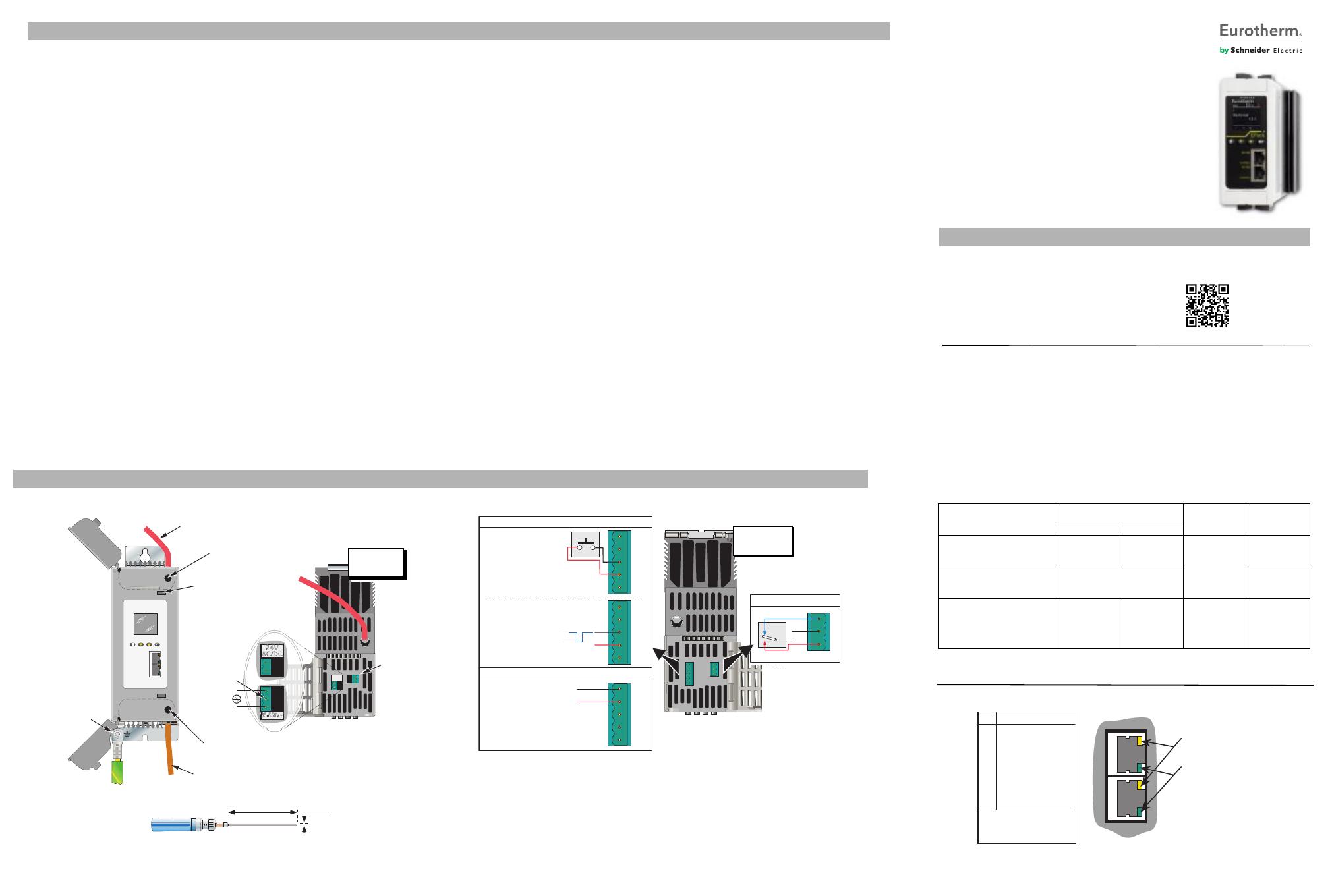
ELECTRICAL INSTALLATION
1 2 3 4 5
04 01 02
1
0V
+
0V
DI1
DI2
1
1
0V
+
0V
DI1
DI2
0V
+
0V
DI1
DI2
02
01
04
com
nc
no
Yellow
Green
Pin Signal
8
7
6
5
4
3
2
1
Not used
Not used
Rx-
Not used
Not used
Rx+
Tx-
Tx+
LEDs:
Green = Tx activity
Yellow = Connected
Contact inputs
Voltage level inputs
Digital inputs
Analogue input
4.4 to 30V = high
-30V to +2.3V = low
2.3V to 4.4V = undefined
V/mA input (note 3)
0 to 10V
1 to 5V
2 to 10V
0 to 5V
0 to 20 mA
4 to 20 mA
Relay output
View on
lower face
500Ω to ∞ = open
0Ω to 150Ω = closed
150Ω to 500Ω = undefined
IO WIRINGSUPPLY WIRING
From Supply power for load
To load
Open the doors by press-
ing in on the catches (two
places) using a suitable
tool such as a screwdriver.
Access to load ter-
mination screw head
Access to supply termination
screw head
60mm minimum
Flat-bladed screw head
1 x 5.5 mm or 1.2 x 6.5mm
recommended
Screwdriver/Torque wrench screwdriver bit details for line and load termination
Neutral
reference
Insulated handle
COMMUNICATIONS WIRING
Centre pin
not connected
HA032269ENG issue 2 June 2016 (CN34584)
Safety earth (M6 nut).
Must be made with a
Listed ring type crimp
Switching characteristics
(resistive loads)
Vmax: 264V RMS
Vmin: 1V dc
Imax: 2A RMS
Imin: 1mA
View on
upper face
Auxiliary voltage alternatives
(as specified at
time-of-order)
SAFETY NOTES
EPack™
Power Controller
DVD CONTENTS AND INSTALLATION
Product documentation. The documentation on this
DVD is in pdf format which requires the use of Adobe® Acro-
bat® 4.0 or later to view it. The English language version of
Adobe Acrobat 4.0 for Microsoft® Windows® may be in-
stalled from this DVD
.
DOCUMENTATION
EPack Controller User Guide HA031414
Eurotherm: International sales and support www.eurotherm.com
Contact Information
Eurotherm Head Office
Faraday Close,
Durrington,
Worthing, West Sussex,
BN13 3PL
Sales Enquiries
T +44 (01903) 695888
F 0845 130 9936
Worldwide Offices
www.eurotherm.com/worldwide
Scan for local
contacts
General Enquiries
T +44 (01903) 268500
F 0845 265982
© Copyright Eurotherm Limited 2016
Eurotherm by Schneider Electric, the Eurotherm logo, Chessell, EurothermSuite, Mini8, Eycon, Eyris, EPower, EPack, nano-
dac, piccolo, versadac, optivis, Foxboro and Wonderware are trademarks of Schneider Electric, its subsidiaries and affiliates.
All other brands may be trademarks of their respective owners.
All rights are strictly reserved. No part of this document may be reproduced, modified, or transmitted in any form by any
means, nor may it be stored in a retrieval system other than for the purpose to act as an aid in operating the equip-ment to
which the document relates, without the prior written permission of Eurotherm Limited.
Eurotherm Limited pursues a policy of continuous development and product improvement. The specifications in this docu-
ment may therefore be changed without notice. The information in this document is given in good faith, but is intended for
guidance only. Eurotherm Limited will accept no responsibility for any losses arising from errors in this document.
Supply cable sizes and torques
Terminals
Terminal capacity
Wire Type Torque
mm² AWG
Supply voltage (1/L1)
and
Load supply (2/T1)
10 mm²
to 50 mm²
AWG 8 to AWG
2/0
Stranded cop-
per rated 90°C
5.6 Nm
(50 Lb.inch.)
Safety earth M6 ring-type crimp terminal
U.L. : Listed ring-type crimp
terminal must be used
5.6 N.m
(50 Lb.inch.)
Phase reference (N/L2) (2-way)
Supply (24V ac/dc) (2-way)
Supply (85V-550Vac)(3-way)
I/O connector (5-way)
Relay connector (3-way)
0.25 mm²
to 2.5 mm²
AWG 24 to
AWG 12
Stranded cop-
per rated 75°C
0.56 Nm
(5 lb. inch)
Warning: Connection of 2 conductors in the same terminal is not allowed.
Notes:
1. DI1 shown; DI2 similar
2. DI1 and DI2 can both be contact inputs or both be voltage inputs or be one of each.
3. Analogue input type (Volts or mA) is selected in I/O Analogue IP configuration. When a mA
range is selected, a suitable shunt resistor is automatically connected into circuit. It is thus un-
necessary for the user to fit external components.
4. Use 0.6 x 3.5 mm screwdriver for pluggable connectors
24. Under some circumstances, the power module heatsink temperature
may rise above 50 degrees Celsius and it can take up to 15 minutes to
cool after the unit is shut down. If operators are likely to come into
contact with such heatsinks, adequate warnings and barriers must be
put in place in order to prevent injury.
25.To reach the thermal performance the gap between two Epack units
should be at minimum 10mm
26. Signal and power voltage wiring must be kept separate from one
another. Where this is impractical, shielded cables should be used for
the signal wiring.
27. To ensure that EPack comply with Electromagnetic Compatibility
requirements, ensure that the panel or DIN rail to which they are
attached is correctly grounded. The ground connection, designed to
ensure ground continuity, is not in any way a substitute for the
protective earth connection.
28. This product has been designed for environment A (Industrial). Use of
this product in environment B (domestic, commercial and light
industrial) may cause unwanted electromagnetic disturbances in which
cases the user may be required to take adequate mitigation measures.
SELV is defined (in IEC60947-1) as an electrical circuit in which the voltage
cannot exceed 'ELV' under normal conditions or under single fault
conditions, including earth faults in other circuits. The definition of ELV
is complex as it depends on environment, signal frequency, etc. See IEC
61140 for further details.
The I/O connector (5-way) & EPack supply (24V ac/dc) (2-way) are
compliant to the SELV requirements.
The alarm relay terminal block named ALR is compliant to the SELV
requirements; it can be connected to SELV or to voltage up to 230V
(Rated insulation voltage Ui : 230V)
SAFETY NOTES
1. Eurotherm shall not be held responsible for any damage, injury, losses or
expenses caused by inappropriate use of the product or failure to comply
with this manual
2. Accordingly the user is responsible for checking, before commissioning the
unit, that all the nominal characteristics correspond to the conditions under
which it is to be installed and used
3. If the equipment is used in a manner not specified by the manufacturer, the
protection provided by the equipment might be impaired.
4. The product must be commissioned and maintained by suitably qualified
personnel, authorized to work in an industrial low voltage environment.
5. BRANCH-CIRCUIT PROTECTION AND SAFETY OVERLOAD PROTECTION
This product does not contain any branch-circuit protection or internal
safety overload protection. It is the responsibility of the user to add branch-
circuit protection upstream of the unit. It is also the responsibility of the user
to provide external or remote safety overload protection to the end
installation. Such branch-circuit and safety overload protection must
comply with applicable local regulations.
UL: The above mentioned branch-circuit protection is necessary for
compliance with National Electric Code (NEC) requirements
6. If opening of the branch circuit protective or the supplemental fuses (high
speed fuse) the product (Epack) shall be examined and replaced if
damaged.
7. The product (Epack) is not suitable for isolation applications, within the
meaning of EN60947-1.
8. The instrument shall have one of the following as a disconnecting device,
fitted within easy reach of the operator, and labelled as the disconnecting
device.
a. A switch or circuit breaker which complies with the requirements of
IEC60947-1 and IEC60947-3
b. A separable coupler which can be disconnected without the use of a
tool.
9. EPack alarms protect thyristors and loads against abnormal operation, and
provide the user with valuable information regarding the type of fault.
Under no circumstances should these alarms be regarded as a replacement
for proper personnel protection. It is strongly recommended that the
installing authority include independent, system-safety mechanisms to
protect both personnel and equipment against injury or damage, and that
such safety mechanisms be regularly inspected and maintained. Consult
the EPack supplier for advice.
10. Units are designed to be installed in a cabinet connected to the protective
earth according to IEC60364-1 and IEC60364-5-54 or applicable national
standards.
11. The cabinet must be closed under normal operating conditions. Adequate
air conditioning/ filtering/ cooling equipment must be fitted to the cabinet
in order to prevent the ingress of conductive pollution, the formation of
condensation etc.
12. We recommend fitting fan-cooled cabinets with a fan failure detection
device or a thermal safety cut-out
13. Before any other connection is made, the protective earth terminal shall be
connected to a protective conductor. Wire conductor cross sections must
comply with table 9 of IEC60947-1 or NEC Article 310 Table 310-16. U.L.:
The earth connection must be made using a Listed ring type crimp. Used
cables must be rated 90°C stranded copper only
14. The earth connection should be tightened at the torque defined in table 2-
1. It is recommended to perform regular inspection of the earth tightening
15. Any interruption of the protective conductor inside or outside the
apparatus, or disconnection of the protective earth terminal is likely to make
the apparatus dangerous under some fault conditions. Intentional
interruption is prohibited.
Whenever it is likely that protection has been impaired, the unit shall be
made inoperative, and secured against accidental operation. The
manufacturers nearest service centre should be contacted for advice.
16. Before carrying out any wiring to the unit it must be ensured that all relevant
power and control cables, leads or harnesses are isolated from voltage
sources.
17. Power connections. Wire conductor cross sections must comply with table 9
of IEC60947-1 or NEC Article 310 Table 310-16. Used cables must be rated
90°C stranded copper only.
18. Power terminals should be tightened according to the torque values
defined in table 2-1. It is recommended to perform regular inspection of
the power terminals tightening.
19. The cable use to connect auxiliary supply should be correctly protected by
a branch-circuit protection. It is the responsibility of the user to add branch-
circuit protection. Such branch-circuit must comply with applicable local
regulations.
20. To comply with safety requirements, the 24V auxiliary supply must be
derived from a SELV or PELV circuit
21. The 85Vac to 550Vac auxiliary supply shall be protected by supplemental
fuse ATM2 rated 600Vac/dc, 2A by MERSEN/Ferraz Shawmut (E33925). The
maximum voltage between any pole of the power supply and terminals 1/
L1, N/L2 should be lower than 550Vac. The maximum voltage between any
pole of the power supply and earth should be lower than 550Vac (rated
insulation voltage 500V)
22. For safety reasons, opening the unit is strictly forbidden.
23. Units are designed to be mounted vertically. There must be no obstructions
(above or below) which could reduce or hamper airflow. If more than one
set of units is located in the same cabinet, they must be mounted in such a
way that air from one unit is not drawn into another.
HA032269_2 EPack Insert.fm Page 1 Tuesday, November 8, 2016 7:56 AM


