
8/3/11JF
OS310U & VS310U Advanced Installation
Purpose
Describes how to install the OS310U or VS310U Motion Sensor in a 3Way switch configuration, where the light is located
between the two switches.
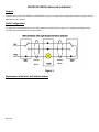
Initial Configuration
The light load is located between the two 3Way switches as shown below in Figure 1. For simplicity the diagram does
not show ground connection for the switch boxes.
Figure 1
Replacement of Switch 1 with Motion Sensor
Traveler
Wires
Wires
Traveler
Wires

8/3/11JF
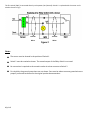
The first switch (SW1) is connected directly to the power (Hot /Neutral). Switch 1 is replaced with the sensor and is
wired as shown in Fig 2.
Figure 2
Notes
The sensor must be located in the position of Switch 1.
Switch 2 must be rewired as shown. The second output of the 3Way Switch is not used.
No connection is required to the second traveler wire that connects to Switch 2.
For simplicity the ground connections are not shown. Care must be taken to ensure ground wires are
properly connected as defined in the original product documentation.
Traveler
Wires
Traveler
Wires
-
 1
1
-
 2
2


Ask a question and I''ll find the answer in the document
Finding information in a document is now easier with AI
Related papers
-
Eaton OS310U-A-K User manual
-
-
-
Eaton OS310U-GY-K User manual
-
-
-
-
-
-
Other documents
-
 Greengate 120V PIR/Single Level Wall Switch Sensor (Ground Required) Installation guide
-
INSTEON Refurbished Remote Control On/Off Switch Owner's manual
-
Jasco 15312 User manual
-
HomeSeer Wired 3-Way Companion Switch User manual
-
-
-
GE SunSmart 15312 Operating instructions
-
Legrand Multi-way Dimming Wall Switch Vacancy Sensor Installation guide
-
Legrand CD-250-W Installation guide
-
 Brilliant BHA120US-WH2 Installation guide

