Page is loading ...

csmqt.com 800.219.8199
Qt
™
300/600
Installation & Operations Guide

page 2
1
2
3
Qt
™
300/600 Quick Installation Guide

page 3
4
5
6
For more information visit csmqt.com
or call 800.219.8199

page 4
Contents
Qt 300/600 Introduction
Hardware Installation
Installing the Control Module
Wall Mount
Rack Mount
Installing Qt Emitters
Emitter Installation Order
Installing Paging or Music to the Audio Inputs
Installing Contact Closures
Custom Cabling Guidelines
Battery Replacement
System Conguration (Front Panel and Monitor Control Software)
System Congurable Feature List (Front Panel / MCS)
Conguring the Control Module for the Network
IP Address DHCP
NETBIOS Support
Other Recommended Connections
Suggestions for Managing Multiple Control Modules
Front Panel Control
System Information
Setting Sound Masking Levels
Setting Audio Input Levels
Lock/Unlock the Front Panel
Congure Network Name and IP Address
Real-Time Clock or Network Clock
Reset System to Default Settings
System Control Using Monitor Control Software (MCS)
Connecting to the Qt 300/600 over Ethernet
MCS: Operation Section
6
8
8
8
9
10
10
12
12
13
14
15
15
16
16
16
16
16
17
17
18
20
20
21
21
21
22
22
23

page 5
Changing Masking Level Using MCS
Auto Ramping
Changing Input A and B Level
Time of Day Masking
Errors
MCS: Administration Section
Service
Zone Names
Networking and Security
Notication of Errors
Date and Time – Time Zone
Setting Equalizers and Emitter Fault Detection
MCS: Help
Links to Help Topics
Software Update
Documentation
MCS: Printout
Error Codes and Message
Post Installation Handoff
Warranty
Warranty
Settings Record
Homerun Zone Destination Record
24
24
25
26
27
27
28
28
28
28
29
30/31
33
33
33
34
34
34
36
37
38
39
40

page 6
Qt 300/600 Introduction
This manual discusses the installation of a sound masking system
using either the Qt 300 or the Qt 600. The Qt 300 and Qt 600
controllers have identical functionality, but different number of
zones supported - the Qt 300 supports 3 zones whereas the Qt 600
supports 6 zones. As you use this guide, remember the number of
zones and total area of coverage is the only real functional difference
between the systems. Collectively, the systems are referred to as
‘QtPro’ throughout this guide.
The Qt 600 supports six zones of sound masking, each with 1 to 120
emitters covering 100 to 12,000 square feet (9.3 m2 - 1,115 m2) per
zone. The Qt 300 supports three zones of sound masking, each with
1 to 120 emitters, covering up to 12,000 square feet per zone (1,115
m2). Each systems comes with two audio inputs which can be used
for paging and/or music. Additional controls for each zone include
time-of-day masking, auto ramping, self-monitoring fault detection
and notication, and independent equalizers for masking and audio
inputs. The system may be operated from its control module front
panel OR by a computer directly-connected to the module OR by
a computer connected through a local area network. See system
conguration on page 15.
It is important that the control module’s masking volumes be set
correctly for each zone to obtain the full effectiveness of the system.
If volumes are set too low, speech privacy will be reduced and work
place distractions will be much more apparent. If volumes are set too
high, the masking sound itself could become a source of distraction.
The higher the setting that can be used comfortably, the better the
acoustic privacy. For a given open ofce design, including ceiling
height, ceiling material and workstation panel height, we can dene
the masking volume required to achieve “normal acoustic privacy,”
i.e., when it is relatively easy to ignore surrounding conversations.
For a very large range of open ofce designs, the target level is
in the 45–48 dBA range, measured 3 ft. (0.9 m) above oor level.
Similarly, for private ofces, based on wall panel design and ceiling
construction, we can dene masking volumes required to achieve
“condential privacy,” i.e., conversations in adjacent ofces cannot
be understood. Most private ofces have a target level in the 38–42
dBA range, averaged spatially within the ofce.

page 7
Setting the masking volumes can be approached in one of two ways:
BEST: If a sound level meter is available, it is recommended that
the control module’s masking volumes be adjusted up or down to
achieve the following readings on the meter:
Private Ofce Zones
38-42 dBA, averaged spatially within the ofce
Open Area Zones
45-48 dBA, measured 3 ft. (0.9 m) above oor level
OTHERWISE: If a sound level meter is not available, the above levels
are likely to be achieved in most environments by setting the control
module’s masking volumes as follows:
Private Ofce Zones
05-09, for all ceiling heights
Open Area Zones
13-16, for 8 ft. (2.4 m) ceilings
15-18, for 10 ft. (3 m) ceilings
17-20, for 12 ft. (3.7 m) ceilings
Masking volumes must be set sufciently high to improve speech
privacy and reduce distraction but not so high that the masking
sound becomes objectionable. Settings within the above ranges
should accommodate both objectives. As a general rule, use the high
end of the range. Base nal settings on site conditions and customer
preferences. If people object to the sound level, set masking volumes
toward the bottom of the range or refer to the ‘Ramping’ section of
this guide, found on page 24 for more information on introducing
masking into the space gradually. Remember that the effectiveness
of the system relies on sufcient masking sound level and that initial
objections are often overcome as people become accustomed to the
sound.
Different day and a night volumes may be set. The control module
ramps linearly between these two settings beginning at the time
specied and over the period of time specied. As the control
module ramps between settings, the current volume is displayed
under “Current.”
NOTE: This document uses the QtPro software version 6.0.0 for
feature conguration.

page 8
Qt 300/600 Introduction
Installing the Control Module
NOTE: Always plug/unplug power supply at wall outlet
NOTE: The Qt 600 is shown in the gures, but the Qt 300 installs in
the same manner.
Wall Mount
Mount the bracket using the three screws and plastic anchors
(mollies) provided. Use a ¼ inch drill bit for the anchor hole. See
Figure 1.
Plastic anchors are #10-12 x 1¼ in. with #10 x 1½ screws.
NOTE: The control module hinges forward for wall mounting and
cable installation. To hinge forward, loosen screws A and B (see
Figure 1) used to secure the module during shipping.
Check to see that the panel lock switch is in the
UN-LOCKED position.
A
B
Figure 1
B3v
Bgnd
M3v
Mgnd
AUDI
O
+
-/L
R
GND
A
B

page 9
Rack Mount
Attach optional rack mount brackets to each end of the control
module.
NOTE: When rack mounted, the control module does not hinge
forward.
Step 1
Remove the QtPro and
power supply bracket from
wall mount bracket.
Step 2
Reassemble power supply
to right rack mount bracket
using 6:32 black screws
(included with bracket).
Step 3
Fasten left and right rack
mount brackets to QtPro
using the screws removed in
Step 1.
Step 4
Mount QtPro to 19” cabinet
rail using 10:32 screws
as shown (included with
bracket).
A
B
B

page 10
Installing the Qt Emitters
Important Considerations:
▪ Each run has a maximum of 60 emitters
▪ Each run should have a maximum length of 1000 ft. (305 m).
▪ Each home run cable attached to the control module should
be labeled by zone # and run #. Adding a logical name (e.g.
Marketing, Private Ofces) is suggested. In addition, ll out
“Home Run Zone Destination Record” at the end of this Guide.
▪ Each zone has two identical outputs, run 1 and run 2. All
emitters on run 1 and run 2 are controlled equally for each zone.
▪ Each job-made cable should be manufactured according to
ANSI/ TIA/EIA Standard 568-B. See custom cabling guidelines
on page 13.
▪ Job-made cables should be tested with a LAN tester before
installation. Adjustable emitters should be set for lower sound
levels, within a zone, when sound level measurements show an
acoustically loud subsection.
Emitter Installation Order
1. Set the masking output level of all zones to level 20.
2. Refer to the emitter layout and wiring diagram provided by the
dealer for cable run connections by zone.
3. Run home run cables from control module to the location of the
rst emitter for all runs in all zones.
4. Gather all ceiling tiles (per layout drawing) that are to receive
emitters. Use the supplied hole saw to cut holes in designated
tiles. Cut all tiles from the front. (Different types of emitter
housings are available to attach in areas where there are no
suspended ceiling tiles.)
5. Push the emitter through the front of the hole in tile and secure
it by pushing down and twisting the locking ring at the back of
the emitter.
6. Connect a run cable from the specied zone OUTPUT jack on
the module to the INPUT jack of the rst emitter. Listen to each
emitter as it is connected. If you cannot hear its “whooshing”
sound:
a. Try a different emitter.
b. Test all four previous cables for continuity and shorts.
Repair any faulty cables.
c. If there is a short, masking volume will shut off. The
short should clear itself in approximately ve minutes.
If it does not, power cycle (unplug and re-plug) the
control module.

page 11
NOTE: The “tombstone” hook on the back of each emitter is next to
the INPUT jack. This can help you nd the INPUT jack by touch.
NOTE: To adjust for unexpected obstacles such as sprinkler heads,
each emitter may be moved up to two feet (one tile) in any direction,
if necessary.
7. Connect the next OUTPUT cable to the emitter OUTPUT jack.
8. Run the cable to next designated tile specied on emitter layout
and wiring diagram. Tie cables up to structure or suspend from
deck as required by local building code.
9. On the next emitter, connect this cable to the INPUT jack.
10. Repeat Steps 4 through 9 for the remaining emitters on the
home run.
11. Set sound masking volume levels for each zone, using either the
front panel controls or the software interface. Set sound levels
according to Table 1.
12. If a small area within a zone exhibits a perceived volume louder
than the rest of the zone, use the adjustable emitter toggle
switches to turn the volume down for the emitters in that area.
Emitters can decrease volume by 3,6 or 9 dB. See emitter spec
sheet for more details.
Be sure to x any problems and hear the “whooshing” sound before
installing the next emitter. If necessary see the Errors section of this
guide, found on page 27.
Note:
The input jack of each emitter bears this symbol
and is located near the safety tie off
The output jack of each emitter bears this symbol

page 12
Installing Paging or Music to the Audio Inputs
1. Be sure power is OFF by unplugging power cord from wall
outlet.
2. Balanced Audio Input: (most often, but not always characteristic
of paging systems.) Connect signal wires to + and - at input A or
B. Connect the shield to GND at the audio source.
3. Unbalanced Audio Input: (typical of music systems.)
a. Mono Signals: Connect signal wire to both L and R at
input A or B. Connect the ground wire to GND.
b. Stereo Signals: Connect signal wires to L and R at
input A or B. Connect the ground wire to GND.
4. If a music source is to be connected, using Input B allows
emergency music shut-off. See Contact Closures below.
Installing Contact Closures
The QtPro provides an instant shut-off capability for masking and/ or
audio Input B if connected to a contact closure interface. The contact
closure utilizes the same style connector as audio Inputs A and B (4-
pin).
To leverage this feature for masking, connect a two-conductor cable
to the two connectors, labeled M3V and MGND. To leverage this
feature for Audio Input B, connect a two-conductor cable to the two
connectors, labeled B3V and BGND.
The other end of these conductors (treated as pairs/circuits) can be
terminated on closure mechanisms of choice.
1. To shut off masking, form a connection between the two “M”
conductors.
2. To resume masking, break the connection (Don’t break the
connectors as you may want to reuse them).
The contact closure for audio Input B follows the same logic.

page 13
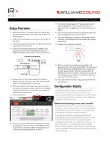
Custom Cabling Guidelines
For system compliance, follow these guidelines if custom cables are
required:
1. Use solid conductor 24 AWG CAT cable that meets local code
requirements.
2. If the system is installed in a return air plenum, the cable must
be plenum rated.
3. Shielding is not required. Unshielded twisted pair (UTP) cable is
acceptable.
4. Snagless boots are not required.
5. RJ-45 plugs must use the “bent 3-tine” RJ 45 plugs intended
for use with solid core CAT wire. Three tine plugs can be
purchased at a hardware store and from most CAT cable
suppliers. DO NOT USE the “aligned two-tine” type intended
for stranded wire, as they provide improper contact and may
yield intermittent system operation. The diagram below shows
the end-on view of both types.
6. Field test each cable after fabrication with the RJ-45 connectors
(before nal installation), using a standard network LAN cable
tester, to check for continuity, shorts, and 1:1 (straight through)
connection.

page 14
Battery Replacement
A coin-style battery (Cr1220 or Br1220) powers the real time clock
during a power loss.
To replace the battery:
1. Unplug the control module from wall outlet.
2. Hinge the control module forward to access the connection
panel.
3. Remove the zone run connections. They should already be
labeled, if not, label before removing (for example: Zone 1 Run
2).
4. Remove the six screws that hold the panel.
5. Taking care not to disturb the other connections, lift the panel
to expose the coin battery in its housing at the front left of the
module.
6. Use a ball-point pen to dislodge the existing battery.
7. Insert a new battery with the positive (+) side facing upward.
8. Replace the connection panel, securing all six screws. Reconnect
the zone run cables.

page 15
System Conguration
After the QtPro is mounted, the power can be turned on and settings
modied to test wiring to the connected emitters. After testing,
it is time to congure the controller for operations. There are two
methods for performing conguration:
1. The front panel display can be used for basic conguration set-
tings to get the system working and tested. In many cases, basic
settings are all that a user needs. This interface only supports a
subset of the functionality.
2. The MCS (Monitor Control Software) interface allows for cong-
uring all the available functionality. The MCS can be used with
any internet browser that can connect to the Qt 300/600 over a
LAN connection. See System Control Using MCS on page 22 for
details.
System Congurable Feature List (Front Panel / MCS)
The following is a complete list of the Qt 300/600 features and if they
can be congured through the front panel, MCS or both.

page 16
Conguring the Control Module for the Network
IP Address DHCP
The IP address is preset for systems that are not on the network. To
directly connect to the control module over Ethernet, the user uses
any internet browser and places the IP address or control module
name in the navigation bar.
If the MCS is not used, DHCP will allocate an IP address when the
system is connected to the network. This eld can be statically set
through the MCS, but it will be dynamically allocated when MCS is
not used.
NETBIOS Support
The system supports NETBIOS and advertises its hostname as QtXX,
where XX is the last two digits of the MAC address. The hostname
may be changed after a connection is made by a browser.
It may be helpful to use hostnames that convey information about
the area served, for example: qt_b1f3 (building one oor three). If
multiple control modules are installed on a single network, be sure
that no two control modules use the same hostname.
Other Recommended Connections
Access to an SMTP server enables the sending of error notication
emails.
Access to an SNTP server obtains the SNTP time stamp. The module
sends its SNTP request to “pool.ntp.org” (by default). If the SNTP
server is enabled, the real-time clock feature is disabled. A time
server other than the default time server may be specied in the
Administration section under date and time.
Suggestions for Managing Multiple Control Modules
Browser bookmarks are a convenient tool for managing multiple
control modules. A bookmark add-on stores bookmarks on a web
server and allows access from any computer on the LAN.
Create a “Sound Masking” folder (under Bookmarks) to hold a
bookmark for each control module. Use location-based names for
each module’s bookmark. To access a specic control module, open
Bookmarks>SoundMasking, and the specic module bookmark.

page 17
Front Panel Control
The front panel is used for conguring basic functionality and initial
system test. For advanced system conguration, the MCS is required.
Once the MCS is used to congure the system, using the front panel
will erase the settings congured by the MCS. Once the MCS is used
to congure the system, it should be used exclusively.
System Information
Initial displays of the front panel, shown below, shows the software
version and system status.
The VERSION X.X.X eld stands for:
major release . minor changes . bug xes.
The HxBx eld is to identify the version of the internal code and used
as reference for technical support on rare occasions.
Status indicates if there are errors (see error codes, page 35) or if
the system is OK. The HxBx eld indicates the version of the internal
code images and is only used by Cambridge Sound Management
when debugging a problem.
The MAC address is displayed for reference when the system is
on the network. The network administrator will need this when
conguring a network connection. This is also used when requesting
an advanced password for the MCS user interface.
Shown in the next block is the display for the IP Address. This is a
default value that can be used in a browser, for direct connection. As
noted, DHCP will change it when the system is on a network
VERSION X.X.X
Status: OK HxBx
IP Address DHCP
169.254.1.1

page 18
Hostname is set at the factory to a default value. This can be changed
through the MCS.
The next 2 blocks show the username and password when connecting
using MCS. The default is admin/secret. These can be changed at the
MCS window.
A warning message is displayed on the front panel after the MCS
is used for conguration (Warning: Time of day Ops). This tells
anyone about to use the front panel that the MCS has been used for
conguration and using the front panel will reset the settings made
by the MCS.
Setting Sound Masking Levels
There is a discussion in the Introduction section for recommended
volume settings.
Settings within the recommended ranges should optimize speech
privacy without excessive distractions. Generally, set masking volumes
toward the high end of the range and adjust according to site
conditions and user preferences. If possible, measure the results with
a sound level meter and check for the achieved sound pressure level.
Adjust as necessary or judge by listening in the area.
Figure 10: The format of the panel for conguring masking. Z1 stands for zone 1
and it is currently set to mute.
Host Name
QT XX
Username
admin
Password
secret
Masking
Z1 Volume: Mute

page 19
If installation occurs before the ofce is occupied, turn the system to
the desired level and leave it at that level. If the system is installed
after the ofce is occupied, turn the system to the correct level when
the space is unoccupied and employ auto ramping, only supported
through the MCS, to provide for a period of acclimatization.
To set the masking level for a zone, use the arrow keys on the front
panel to move to the right until the zone of interest is shown (Z1 is
zone 1 which matches the rst column of ports on the back). Then use
the up and down arrows to change the value.
After setting the value for one zone, arrow to the right or left to
set the value for zone of interest. Repeat for all zones. If a portion
of a zone is louder than the rest of the zone due to a difference in
acoustics, it should either be a different zone of the volume lowered
using the adjustment on the back of the emitters. The volume will still
change based on the value of the controller, but the output can be
turned down 3,6 or 9 dB from the value set at the controller.
IMPORTANT:
For full system effectiveness, it is essential to set the volumes
correctly for each zone.
If the volume is set too low, speech privacy is reduced and workplace
distractions are more apparent.
If too high, the masking sound can become a distraction. Since,
in general, acoustic privacy improves as sound masking volume
increases, the general strategy is to set the masking volumes as high
as possible without being distracting.
NOTE: If making adjustments from the front panel, do not disconnect
power for 10 minutes after setting values, or data may be lost. If
adjustments are being made via the web interface, there is no need
to wait.

page 20
Setting Audio Input Levels
The system has two inputs for paging or music. Either input may be
connected to any or all zones via software or front panel interface. If
no paging and/or music from these inputs are desired in a particular
zone, set the audio volume level of that zone to mute.
Note that Input B is the preferred music input due to its ability to be
shut down via a contact closure.
The audio input levels are set in a similar way as the masking. Use the
arrows on the front panel to move left and right to nd the input A
and input B eld for each zone. The inputs are enabled and level set
for each zone for exibility. Arrow to each zone for each input and set
the level using the up and down arrows.
Lock/Unlock the Front Panel
The settings of the Qt 600/Qt 300 can be locked by a physical switch
on the back of the control module. Lock the control module panel by
moving the “lock” switch to the “Locked” position. This prevents any
casual interaction from changing the settings.
Unlock the Front Panel and Control the System
1. Loosen screws and lift the control module slightly and hinge it
forward to give access to its connection panel.
2. Move the panel lock switch to the UNLOCKED position. Close
the module.
3. Press NEXT or PREVIOUS to scroll between screens for adjusting
sound masking, paging or music volumes by zone.
4. Modify a value by 1 dB on any screen by pressing + or -.
5. Press NEXT to accept a screen value.
6. After completing adjustments, lock the system.
NOTE: The system returns to the Version, Status screen after ve
minutes of inactivity. Z1 indicates Zone 1, Z2 indicates Zone 2, etc.
If an error is detected, an error code is displayed on the control
module. See page 35 for details about Error Codes.
This gure shows the format of the panel for conguring the volume for input A or
B. The level of the input is set for each zone, where the example shows Input A is
level 6 for zone 1.
Input A
Z1 Volume: 6
/